J. Cent. South Univ. (2017) 24: 947-956
DOI: 10.1007/s11771-017-3497-6

Dynamic responses of K-type and inverted-K-type jacket support structures for offshore wind-turbines
LIAO Ying-di(БОУж·)1, 2, GUO Meng-yuan(№щГОФІ)1, 2, WANG Na(НхДИ)1, 2,
HOU Li-jun(єоАыѕь)1, 2, CHEN Da(іВґп)1, 2
1. Key Laboratory of Coastal Disaster and Defence, Ministry of Education (Hohai University), Nanjing 210098, China;
2. College of Harbor, Coastal, and Offshore Engineering, Hohai University, Nanjing 210098, China
 Central South University Press and Springer-Verlag Berlin Heidelberg 2017
Abstract: The jacket structure has become more popular as the offshore wind-turbine support structure. K-type and inverted-K-type jacket support structures have superior potential due to their fewer joints and lower cost of manufacture and installation. A numerical study was presented on the dynamic responses of K-type and inverted-K-type jacket support structures subjected to different kinds of dynamic load. The results show that the inverted-K-type jacket structure has higher natural frequencies than the K-type. The wave force spectrum response shows that the maximum displacement of the K-type jacket structure is larger than that of the inverted-K-type. The time-history responses under wind and wave-current load indicate that the inverted-K-type jacket structure shows smaller displacement and stress compared with the K-type, and presents different stress concentration phenomena. The dynamic responses reveal that the inverted-K-type of jacket support structure has greater stiffness and superior mechanical properties, and thus is more applicable in the offshore area with relatively deep water.
Key words: jacket support structure; K-type; inverted-K-type; foundation; dynamic responses
1 Introduction
In recent years, renewable energy has been attached with great importance for environment protection and durable development. In the case of electricity, offshore wind energy has been gradually used as important sources to decrease the reliance on the traditional coal- fired power. This clean resource has grown enormously over the last decades, which produced more than 10% of all electricity in certain regions in Europe [1]. It should be noted that the safety of wind-turbine support structures under dynamic and fatigue load plays a key role in the whole offshore wind power system [2, 3].
The offshore wind-turbine support structure comprises two parts: the lower foundation and the upper tower. According to DNV code, the lower foundation can be classified as gravity, monopile, tripod, jacket, suction, and floating, etc [4]. From this perspective, the type of a support structure is generally determined by the type of lower foundation. Recently, the offshore wind farms gradually develop towards the open seas, and a series of construction difficulties for installing the wind-turbine support structures has been encountered [5]. However, the jacket support structure can be prefabricated in whole and shows superiority in construction, load carrying capacity and structural property. Therefore, the jacket support structure has a great potential to be applied to wind farms in open seas with water depth beyond 40 m in the near future.
The offshore wind-turbine support structures are subjected to the complex dynamic loads such as wind, wave, current and ice loads, etc [6]. For the wind load, a mean load was proposed through introducing a peak factor which considers non-Gaussianity, spatial correlation of wind load on transmission [7, 8] and resonance response [9]. Based on the calculation theory on the dynamic response of inland wind-turbine support structures proposed by LOBITZ et al [10], OSCAR et al [11] further studied the displacement response of offshore wind-turbine support structures with consideration of random wind and wave loads. CHENG [12] found that the delay of the ultimate wave height after the maximum gust made the dynamic response of the whole structure decrease, which provided an effective way to consider the combined wave and gust loads. The dynamic analysis on the monopile and tripod offshore wind-turbine support structures carried out by LIU [13] indicated that the interaction between tower and wind-turbine blade had little influence on the structural response. Based on the nonlinear regular wave-current theory and Morison equation, CHEN et al [14] proposed the offshore wind-turbine load and dynamic response models considering the coupling effect between wind and wave, and in the meanwhile the corresponding calculation program was developed.
In the case of upper tower of support structures, BAZEOS et al [15] investigated the static, seismic, and stability capabilities of the monopile support structure of a wind turbine and found that refined finite-element models were necessary at specific critical locations for a more accurate structural analysis. Also, LAVASSAS et al [16] made structural analysis and design of prototype of a steel 1 MW wind-turbine tower. The results showed that the buckling analysis of the tower shell based on Eurocodes was unreliable, and the extreme wind can serve as the dominated load combination for the tower design. Besides, the structure optimization of wind- turbine tower carried out by NEGM and MAALAWI [17] indicated that maximization of a weighted-sum of the system natural frequencies was the most representative objective function for ensuring a balanced improvement in mass and stiffness.
Based on the configuration mode of inclined strut, jacket support structures can be classified as X-type, diagonal-type, broken-line-type, K and inverted-K-type [4]. Compared with rods in X-type and diagonal-type jacket structures, members in K-type and inverted-K- type jacket structures have larger cross section and weight, and present more reasonable mechanical properties with fewer joints and slighter stress concentration phenomenon. Therefore, the K-type and inverted-K-type jacket structures show a relative advantage in the engineering application. However, up to now, the configuration of inclined struts in the practical engineering still depends on the experience of engineers [18]. Besides, the recent studies on the offshore wind- turbine jacket support structures mainly focus on the static analysis whereas the dynamic analysis is still little yet. The objective of this present paper is to investigate the dynamic responses of K-type and inverted-K-type jacket support structures through the ANSYS software which will provide a significant reference for the engineering design.
2 Models of jacket support structures
2.1 FEM model
The jacket support structures have the same upper tower but different lower jacket foundations with the arrangement of inclined strut as K-type or inverted-K- type. For making a simplification of the wind-turbine set in these two structural models, the wind-turbine load due to the running of blade can be directly applied on the top of upper tower.
These two jacket support structures are simulated based on the actual wind-turbine support structures in the Donghai wind farm. Correspondingly, the environment conditions are described as follows: 45 m in water depth, 30 m/s in wind speed at the 10 m height above the sea surface, 13.2 m in the effective wave height, 9.6 s in effective wave cycle, 2.4 m/s in current speed at the sea surface, 1.9 m/s at the middle height of sea, 1.2 m/s on the bottom of sea, and 1025 kg/m3 in the density of sea water.
The upper tower and lower jacket foundation are both made of steel tube with different diameter and thickness. Their detailed geometry parameters are summarized in Table 1. All the steel pipes are made of the D36 steel which has the elastic modulus of 200 GPa, the Poisson ratio of 0.3, the density of 7850 kg/m3 and the yielding strength of 360 MPa.
Table 1 Geometry parameters of models

These two models have the same materials, element properties and geometry size. The upper tower is 95 m in height, and both the jacket foundations are composed of four layers with the spacing of 15 m. The main pipe, horizontal and inclined struts of jacket above the surface of mud are modeled using PIPE59 member provided in ANSYS program, which is capable of considering the combined wave and current loading. PIPE20 member provided in ANSYS program is applied for modeling upper tower and the steel pipes of jacket below the surface of mud. The intersection between pile and soil is ignored and the main pipes of jacket foundations are fixed at 6 times of pile diameter (5 m for the present case) below the mud surface. Figure 1 shows the isometric and elevation views of two types of jacket support structures.
The coordinate of key positions along vertical direction of jacket structure is shown in Fig. 2. The coordinate origin O is located at the center of the second layer of jacket, corresponding to the location of the still sea level. The upper tower top is at the location of +95 m. The top of lower jacket foundation is at the height of +15 m, and the lowest layer of jacket is located at the seabed (-45 m). And, the fixed end is located at -50 m.
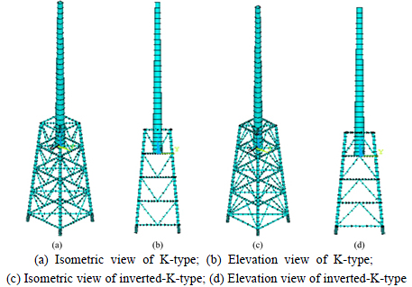
Fig. 1 Models of K and inverted-K types of jacket structures:
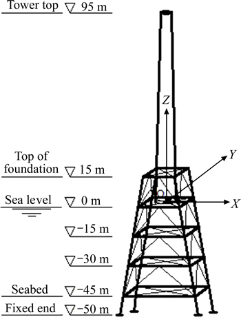
Fig. 2 Coordinate system of jacket structure
2.2 Applied loads
Unlike the wind-turbine support structure on the land, the offshore wind-turbine support structures within the ocean environment are subjected to wave and current loads in addition to wind load and the gravity of structure and wind-turbine.
2.2.1 Wave force spectrum
The wave force spectrum analysis can be used to evaluate whether the resonance of jacket structure can take place under the wave loading. It is assumed that the response of offshore structures is linearly related with the wave action. The stationary random function can be transformed in the stationary linear system. The wave force spectrum of offshore structures is given by [19]
 (1)
(1)
where ¦Ш is the circular frequency of wave, S¦З(¦Ш) is the wave spectrum of system, SY(¦Ш) is the response spectrum of system, and |T(i¦Ш)|2is the frequency response function termed as a transfer function of system.
The P-M spectrum is used in the present work:
 (2)
(2)
where H1/3 is the wave height of effective wave. Then, the wave force spectrum at the height z is given by

 (3)
(3)
where CD is drag force coefficient, CM is inertia force coefficient, ¦С is the density of sea water, D is the diameter of pile, k is the number of wave, d is design water depth, and ¦Тu is the function of z which can be expressed as

 (4)
(4)
The total wave force spectrum can be expressed as

 (5)
(5)
Substituting Eq. (4) into Eq. (5) yields

 (6)
(6)
At the calculation of wave force spectrum, the inertia force coefficient CM and drag force coefficient CD are taken as 2.0 and 1.0, respectively. The calculated wave force spectrum is illustrated in Fig. 3. It can be observed that the maximum wave force is 27.34 kN at the ¦Ш of 0.143 Hz.
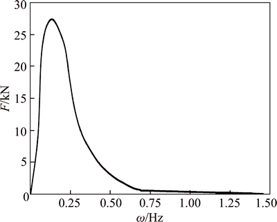
Fig. 3 Wave force spectrum
2.2.2 Wind load
The wind-turbine takes the SL3000 offshore type with unit capacity of 3.0 MW made by Sinovel Wind Group Co., Ltd whose gravity including engine room and blade is about 1900 kN. The horizontal load under the normal wind is 828 kN. These two loads are supposed to be directly applied on the top of upper tower in the present work, i.e., the concentrated load applied on the tower top are Fx=828 kN and Fz=-1900 kN, respectively.
The upper tower is high up to 95 m, and the wind speed is simulated at five typical points including 15 m, 35m, 55m, 75 m and 95 m above the sea level. The wind- turbine is located at the open sea, and the corresponding ground roughness coefficient k is taken as 0.002. The wind speed history of offshore wind-turbine is simulated based on the linear filtering method [20], and the wind pressure W(z,t) at the time t and height z can be written by


 (7)
(7)
where ¦С is the density of air, us is the shape factor,  is the average speed at the height z, u(z,t) is the fluctuating speed at the height z, and
  is the average wind press at the height z. Then, the wind load F(z,t) applied on the unit height of tower can be given by
 (8)
(8)
where A(z) is the windward area in the range of unit height. The wind load history curves applied on the tower at the height of 15 m, 35 m, 55 m, 75 m and 95 m are shown in Fig. 4.
2.2.3 Combined wave-current loading
The wave-current action on the offshore structures is a type of fluid dynamic effect arising from the fluid particle moving. The combined wave-current load is given by the load module of ANSYS program. During the calculation, the parameters related with current of different water depth need to be defined in addition to the wave parameters CD and CM. The detailed parameters for wave-current load are listed in Table 2.
At calculating the wave-current load, the parameter values used are presented as follows: KWAVE=2 represents the use of stokes wave theory; KCRC=0 denotes the wave-current action along the direction of wave action; DEPTH=45 m is the water depth; DENSW=1025 kg/m3 is the density of sea water; ¦Иw is the angle between the induced-wave and the structure; Z(1), Z(2) and Z(3) are the coordinate value at the bottom, middle and surface of sea, taken as -45 m, -22.5 m and 0 m, respectively; W(1), W(2) and W(3) denote the current speed at Z(1), Z(2) and Z(3) taken as 1.2 m/s, 1.9 m/s and 2.4 m/s, respectively; ¦Иd(1), ¦Иd(2) and ¦Иd(3) are the angle between wave and current at Z(1), Z(2) and Z(3) taken as 0Ўг due to the assumption of identical wave and current direction; A(1)=13.2 m is the wave height; ¦У(1)=9.6 s is the wave cycle; ¦Х(1) is phase angle in the range of 0Ўг-360Ўг. The computed combined wave-current load curve with the change of phase angle is shown in Fig. 5. The maximum wave-current force of 1293 kN is reached at the phase angle ¦Х(1) of 51Ўг.

Fig. 4 Wind load history curves applied on tower:
Table 2 Parameters of combined wave-current load

3 Dynamic responses and discussion
3.1 Modal characteristics
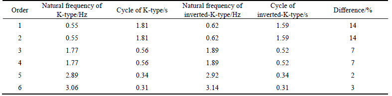
The Block Lanczos method is used to analyze the modal characteristics of jacket support structures. The calculated natural frequencies are summarized in Table 3.
Observe that the natural frequencies of inverted-K jacket structure are higher than that of the K-type. In detail, compared with K jacket structure, the inverted-K jacket structure has 14% larger for the first two frequencies and 7% larger for the third and fourth frequencies. It is concluded that with almost the same gravity, the inverted-K jacket structure has larger stiffness than the K-type.
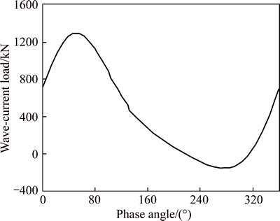
Fig. 5 Combined wave-current force
Table 3 Natural frequencies of two jacket support structures
3.2 Wave force spectrum response
The spectrum analysis of jacket support structure can be carried out to adjust the structural frequency far away from the load frequency for avoiding the structure resonance. Based on single particle response method, the displacement response under wave force spectrum is calculated through applying the wave force spectrum on two nodes of main pipes of the jacket at 10 m height.
The computed lateral displacement response curves at the representative locations of inverted-K and K jacket support structures are shown in Figs. 6 and 7. From these two figures, the maximum displacement at tower top is presented at the first two frequencies of 0.5501 Hz for the K-type jacket structure and 0.6271 Hz for the inverted-K-type. Besides, the maximum displacement is reached at the third and fourth frequency of 1.771 Hz and 1.8988 Hz for both jacket foundations, respectively.
It is pointed out that the second frequencies of both support structures are relatively close to the basic frequency of single tower itself, and thus the resonance of upper tower may occur at this frequency. Correspondingly, the third and fourth frequencies are close to the basic frequency of single jacket structure, and the lower jacket foundation presents similar resonance at this frequency. Compared the displacement response curves shown in Figs. 6 and 7, the maximum displacement of K jacket structure is larger than that of the inverted type, which demonstrates a higher lateral stiffness of the inverted-K jacket structure than that of the K-type.
3.3 Time-history response under wind loading
The displacement and stress responses of both jacket structures are obtained through applying the wind time-history load presented above on the upper tower. Figure 8 shows the comparison of the maximum displacement, the maximum stress and the mean stress (mean of all the nodal absolute stress at the same height). The key positions inspected include the 95 m, 75 m, 55 m and 35 m of the upper tower, 15 m, 0 m, -15 m, -30 m and -45 m of the lower jacket foundation, and -50 m of the fixed end.
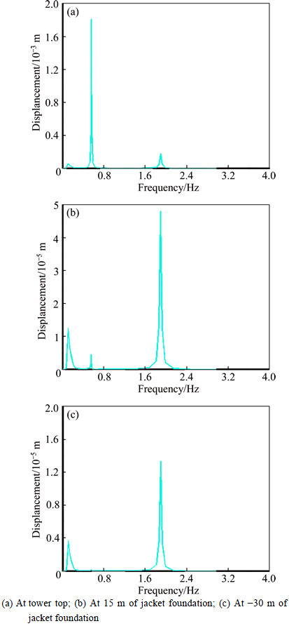
Fig. 6 Displacement response curves of inverted-K-type:
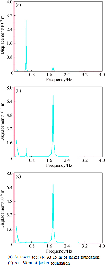
Fig. 7 Displacement response curves of K-type:
As shown in Fig. 8(a), a similar displacement variation trend is observed for two jacket structures with the maximum displacement at the tower top and a gradual decrease from the top to fixed end. The displacements at the tower top of inverted-K-type and K-type structures are 0.7461 m and 0.7975 m, respectively, with a difference of 7%, whereas the displacements at the top of jacket foundations are 0.052 m and 0.0664 m, respectively, with a difference of 20%. This indicates that the inverted-K jacket structure has a larger stiffness, and the structure stiffness shows a more apparent effect on the displacement response of the lower foundation.
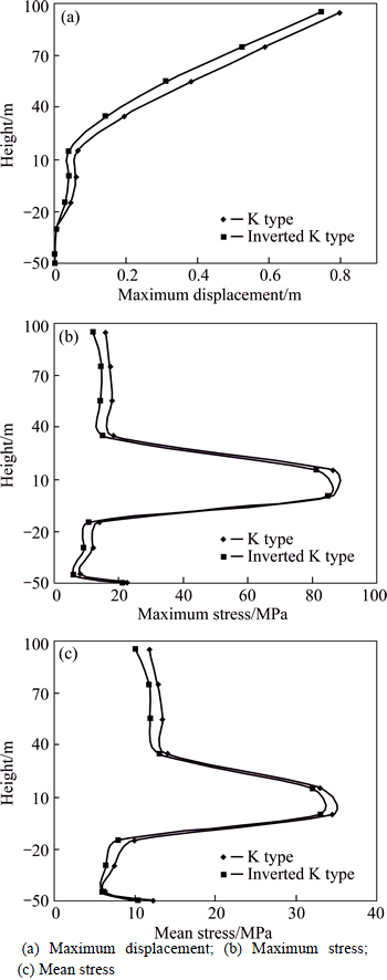
Fig. 8 Response comparison of jacket structures under wind loading:
It is found from Figs. 8(b) and (c) that the stress concentration phenomenon is presented for both jacket structures at the intersections between the tower and the first layer of jacket and between the inclined and horizontal struts at the second layer of jacket. The maximum stress values are 82.5 MPa and 86.5 MPa for inverted-K-type and K-type support structures, respectively. If ignoring the stress concentration, both the maximum stress and mean stress of lower jacket foundation are higher than that of upper tower. This may be due to the mechanical property of truss structure of jacket foundation superior to that of upper cantilever tower.
Compared the displacement and stress results shown in Fig. 8, the K-type jacket structure has larger displacement and stress than the inverted-K-type regardless of the upper tower and the lower jacket foundation. As a result, the inverted-K-type jacket structure presents more apparent potential than the K-type under the same environment.
3.4 Time-history response under combined wave- current loading
Figure 9 shows the structural responses under the combined wave-current load, such as the maximum displacement, the maximum stress and stress amplitude (denoting the absolute difference between the nodal stress peak and valley at the same height). The structure positions inspected are similar to that presented in time-history response under wind load.
As shown in Fig. 9(a), the displacement gradually decreases from tower top to fixed end of foundation for both jacket support structures with the maximum displacement of 0.078 m and 0.102 m for inverted-K and K structures, respectively. It is found from Figs. 9(b) and (c) that the maximum stress under combined wave- current load occurs at the intersection position between upper tower and the first layer of jacket foundation, with the maximum stress of 90 MPa and 110 MPa. And a stress concentration phenomenon is presented at the top of lower foundation. The wave loading is mainly applied on the foundation above the sea level, and the current load gradually decreases with the increase in water depth. Thus the wave-current load makes a large effect on the lower foundation, especially the first two layers of jacket close to the sea level.
Compared the curves shown in Figs. 9(b) and (c), the K-type jacket structure has larger displacement and stress than the inverted-K-type. Compared with upper tower, the lower foundation of the K-type jacket structure shows a large variation of stress amplitude apparently, whereas the corresponding change becomes relative gentle for the inverted-K-type jacket structure. Consequently, the inverted-K-type structure has superior mechanical properties to that of the K-type structure.
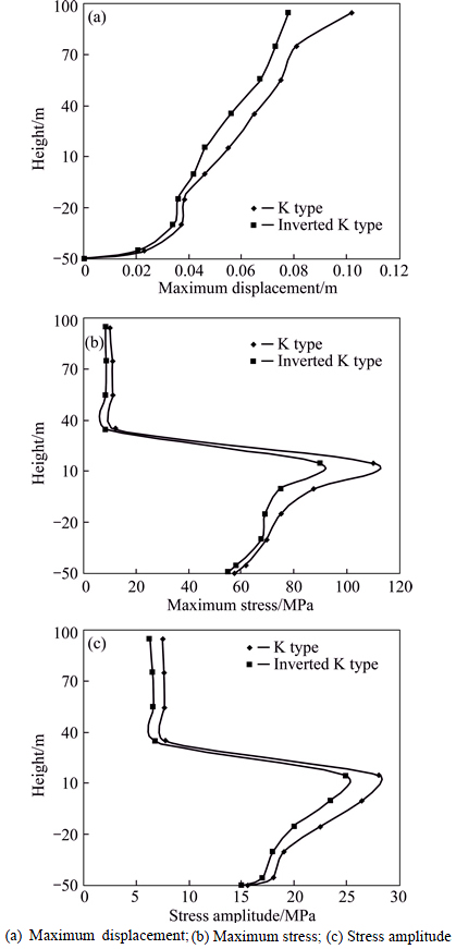
Fig. 9 Response comparison of both jacket structures under combined wave-current loading:
Figure 10 shows the comparison of displacement and the maximum stress responses under wind and wave-current load. It is observed that the displacement and stress responses of upper tower under wind loading are both larger than that under wave-current load. The stress concentration phenomena under wave-current load and the wind load are different from each other. Unlike the stress sudden variation presented both on the top of foundation and the bottom end of tower under wind load, the drastic stress variation occurs only at the top of jacket foundation subjected to wave-current load. In addition, it is revealed from Fig. 10(b) that the wave-current loading plays a control role for the lower jacket foundation. Compared with the K-type structure, as shown in Fig. 10, the inverted-K-type support structure presents larger displacement and stress responses under different loads. Therefore, the inverted-K-type support structure has superior potential to the K-type structure.
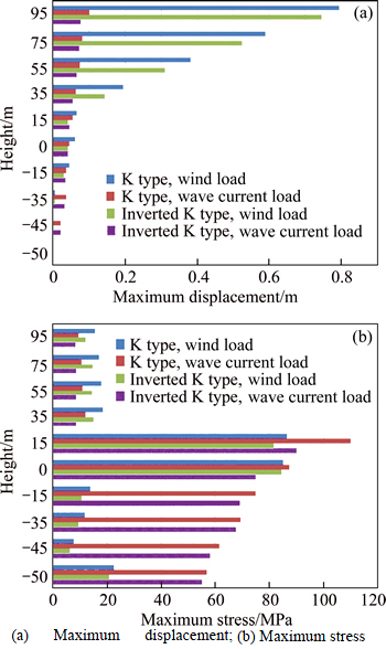
Fig. 10 Comparison of structure response under wind and wave-current loading:
4 Conclusions
1) The inverted-K type support structure has larger natural frequencies than the K-type with 14% larger for the first two frequencies and 7% larger for the third and fourth frequencies.
2) The wave force spectrum response indicates that the resonance may occur at the first two frequencies for the upper tower whereas the resonance of lower jacket foundation may take place at the third and fourth frequencies. Besides, the displacement response of the K-type support structure is larger than that of the inverted-K-type structure.
3) The time-history response under wind loading reveals that the K-type support structure presents more apparent displacement and stress responses compared with the inverted-K-type structure regardless of upper tower and lower jacket foundation. The stress concentration phenomenon is shown at the intersections between the tower and the first layer of jacket and between the inclined and horizontal struts of the second layer of jacket.
4) The displacement and stress responses of the K-type jacket structure under combined wave-current loading are larger than that of the inverted-K-type structure. The stress concentration occurs on the top of lower foundation for both jacket structures. In comparison with the K-type jacket structure, the lower foundation of the inverted-K-type jacket structure has a relatively gentle variation of stress amplitude.
5) The dynamic analysis indicates that the inverted- K-type wind-turbine support jacket structure has larger stiffness and superior structural properties compared with the K-type. Thus, the inverted-K-type jacket structure presents more potential in the offshore wind farm with relatively deep water.
References
[1] HENDERSON A R, MORGAN C, SMITH B, SORENSEN H C, BARTHELMIE R J, BOESMANS B. Offshore wind energy in EuropeЎЄA review of the state-of-the-art [J]. Wind Energy, 2003, 6(1): 35-52.
[2] CHEN Da, HUANG Kai, BRETEL V, HOU Li-Jun. Comparison of structural properties between monopile and tripod offshore wind-turbine support structures [J]. Advances in Mechanical Engineering, 2013: 1-9.
[3] SCHAUMANN P, LOCHTE-HOLTGREVEN S, STEPPELER S. Special fatigue aspects in support structures of offshore wind turbines [J]. Materials Science and Engineering Technology, 2011, 42(12): 1075-1081.
[4] SCHARFF R, SIEMS M. Monopile foundations for offshore wind turbines-solutions for greater water depths [J]. Steel Construction, 2013, 6(1): 47-53.
[5] DNV-OS-J101. Design of offshore wind turbine structures [S].
[6] LI Wei, ZHENG Yong-min, LU Fei, LUO Jin-ping, JIANG Zhen-qiang, HUAN Cai. Dynamic analysis of foundational structure for offshore wind turbine [J]. Marine Science Bulletin, 2012, 31(1): 67-73. (in Chinese)
[7] NISHIJIMA K, KANDA J, CHOI H. Estimation of peak factor for non-Gaussian wind pressure [J]. Journal of Structural Construction Engineering, 2002, 557(7): 79-84. (in Japanese)
[8] ISHIKAWA T. A study on wind load estimation method considering dynamic effect for overhead transmission lines [D]. Tokyo: Waseda University, 2004. (in Japanese)
[9] BINH L V, ISHIKAWA T, PHUC P V, FUJINO Y. A peak factor for non-Gaussian response analysis of wind turbine tower [J]. Journal of Wind Engineering and Industrial Aerodynamics, 2008, 96(10, 11): 2217-2227.
[10] LOBITZ D W. A Nastran-based computer program for structural dynamic analysis of horizontal axis wind turbines [C]// Proceedings of the Horizontal Axis Wind Turbine Technology Workshop. Department of Energy and NASA-Lewis, Cleveland, 1984, 385-393.
[11] OSCAR D S, PAEZ T L. Analysis of wind turbines on offshore support structures excited by random wind and random waves [R]. Albuquerque: Sandia National Laboratories, 1988.
[12] CHENG P W. A reliability based design methodology for extreme responses of offshore wind turbines [D]. Delft, Netherlands: Delft University, 2002.
[13] LIU Zhi-qiang. Dynamic responses analysis of wind turbine tower subjected to environmental load [D]. Dalian: Dalian University of Technology, 2009. (in Chinese)
[14] CHEN Xiao-bo, LI Jing, CHEN Jian-yun. Calculation of the nonlinear wave force of offshore wind turbine based on the stream function wave theory [J]. Journal of Hunan University (Natural Sciences), 2010, 38(3): 22-28. (in Chinese)
[15] BAZEOS N, HATZIGEORGIOU G D, HONDROS I D, KARAMANEAS H, KARABALIS D L, BESKOS D E. Static, seismic and stability analyses of a prototype wind turbine steel tower [J]. Engineering Structures, 2002, 24(8): 1015-1025.
[16] LAVASSAS I, NIKOLAIDIS G, ZERVAS P, EFTHIMIOU E, DOUDOUMIS I N, BANIOTOPOULOS C C. Analysis and design of the prototype of a steel 1-MW wind turbine tower [J]. Engineering Structures, 2003, 25(8): 1097-1106.
[17] NEGM H M, MAALAWI K Y. Structural design optimization of wind turbine towers [J]. Computers & Structures, 2000, 74(6): 649-666.
[18] YI Wei, SONG Yu-pu, ZHANG Yan-kun. Style selection and optimum of offshore concrete platform [J]. Acta Oceanologica Sinica, 1999, 21(3): 126-133. (in Chinese)
[19] YU Yu-xiu. Random wave and its applications to engineering (the third edition) [M]. Dalian: Dalian University of Technology Press, 2003, 356-359. (in Chinese)
[20] LI C X, DU M, HAN B K. Simulation of fluctuating wind speed time series of super-tall building based on AR model [J]. Journal of Earthquake and Engineering Vibration, 2008, 28(3): 87-92.
(Edited by YANG Bing)
Cite this article as: LIAO Ying-di, GUO Meng-yuan, WANG Na, HOU Li-jun, CHEN Da. Dynamic responses of K-type and inverted-K-type jacket support structures for offshore wind-turbines [J]. Journal of Central South University, 2017, 24(4): 947-956. DOI: 10.1007/s11771-017-3497-6.
Foundation item: Project(51509081) supported by the National Natural Science Foundation of China; Project(B12032) supported by the Ў°111 ProjectЎ± of China; Projects(BK20150037, BK20150811) supported by the Natural Science Foundation of Jiangsu Province, China
Received date: 2015-07-29; Accepted date: 2015-12-17
Corresponding author: CHEN Da, Professor, PhD; Tel: +86-25-83787383; E-mail: chenda@hhu.edu.cn

