J. Cent. South Univ. (2012) 19: 1002-1009
DOI: 10.1007/s11771-012-1103-5
Penetration depth for yaw-inducing bursting layer impacted by projectile
CHEN Wan-xiang(陈万祥)1, GUO Zhi-kun(郭志昆)2, QIAN Qi-hu(钱七虎)2,YE Jun-hua(叶均华)2, XU Xiao-zhuang(徐小壮)2
1. School of Civil Engineering and Transportation, South China University of Technology,Guangzhou 510640, China;
2. Engineering Institute of Corps of Engineers, PLA University of Science and Technology,Nanjing 210007, China
? Central South University Press and Springer-Verlag Berlin Heidelberg 2012
Abstract: In order to accurately estimate the anti-penetration capacity of yaw-inducing bursting layer with irregular barriers on surface impacted by projectile, the theoretical model of attack angle and angular velocity for projectile impacting on irregular barrier was achieved according to the macroscopic relation of contact force versus contact time, in which the main factors such as the relative geometrical characteristics of projectile and irregular barrier, material property and impact velocity of projectile influencing on yaw-inducing effectiveness were considered. On the basis of considering synthetically the influences of attack angle, impact velocity, impact angle of projectile and uncontrolled free surface of target, the theoretical formulation of penetration depth for bursting layer with irregular barriers on surface impacted by projectile was presented by expressing the stress of an optional point on the nose of projectile according to the relation of stress versus velocity. The theoretical results indicate that in the case of oblique impact embodying effect of attack angle, the penetration depth is reduced with the increase of impact angle, attack angle or angular velocity, and penetration trajectory is also deflected obviously. The effectiveness of angular velocity influencing on penetration depth is increased with impact velocity increasing. The theoretical results are in good agreement with test data for low impact velocity.
Key words: solid mechanics; penetration depth; contact mechanics; computation method; yaw-inducing bursting
1 Introduction
With the rapid development of deep penetration weapons such as the laser-guided penetration weapons of GBU series, their impact velocities are about 1 000- 2 000 m/s, and they are mainly used to destroy the hard protective engineering of underground with burying depth over 100 m and can penetrate through concrete target with thickness of 6-18 m [1]. Obviously, the capacity of protective engineering by is improved only enhancing material strength of bursting layer. On the other hand, some new defense techniques must be explored for protective engineering. Nowadays, the protective engineering with deep burying is faced with fearful menace, and the experts about protective engineering all over the world make great efforts to investigating new defense techniques.
Experimental studies on the anti-penetration capabilities of various bursting layers consist of soil, rock or concrete, and bursting layers with different configurations were carried out by many scientific research groups in USA and Germany since 1960s. In order to investigate the influences of configurations of bursting layers on the yaw-inducing effectiveness, experimental researches on anti-penetration capabilities of bursting layers with rock-bubble/boulder overlays were carried out, at Tyndall Air Force Base (AFB) [2] and Waterways Experiment Station (WES) [3-4]. respectively. Large numbers of prototype tests and model tests for bursting layers with rock overlays were carried out in Germany [5]. In addition, the system consisting of a reinforced concrete deflection grid and the burster slab to deflect and stop the penetrator was investigated at Air Force Civil Engineering Station (AFCESA) [5]. Anti- penetration capacities of yaw-inducing deflection grids for defeating advanced penetration weapons were experimentally studied at Tyndall Air Force Base (AFB) from 1991 to 1992 [5]. For above experiments, it was indicated that the yaw-inducing techniques for defeating deep penetration weapons or in particular the weapons with large ratio of length to diameter were very effective. In fact, the yaw-inducing conception was first presented by ROHANI [6]. It was supposed that the penetration capabilities of penetration weapons can be weakened greatly when they were induced to yaw before impacting on the bursting layers; as a result, the bodies of penetration weapons would be damaged by unsymmetrical impact force to some extents.
The research works on yaw-inducing mechanisms and shielding effectiveness of bursting layers with irregular barriers on surface were mostly conducted by means of experiments, and the relations between yaw-inducing effectiveness and the parameters of projectiles or irregular barriers could not be explained quantificationally. There were few researches on the yaw-inducing mechanisms of projectiles because the complicated subject involved the theories of solid dynamic mechanics, and no computation method can be used to estimate the penetration depths for yaw-inducing bursting layers impacted by projectile yet. The deflexion angles of projectiles versus the initial deflexion angles and cannon-shots were given, and the influences of the initial deflexion angles, initial velocities of projectiles and the material densities on the deflexion angles of projectiles were experimentally investigated [7]. It was supposed that the final deflexion angles of projectiles were relative to the initial deflexion angles and initial velocities of projectiles geometrically, but not the functions of material properties. The normal and tangential contact forces for projectiles impact on irregular barriers were presented by WANG et al [8], and the computation formulas for velocities and angular velocities when projectiles impacts on irregular barriers were given by means of introducing the restitution coefficients [9]. In those researches, the theoretical formulation for penetration depths of projectiles was not given in detail and the restitution coefficients were thought to be constants.
In this work, to overcome the disadvantages of the works mentioned before, theoretical formulation of penetration depth for bursting layer with irregular barriers on surface impacted by projectile was presented. The contact model was developed based on the theory of contact mechanics, and theoretical formulas for effect of attack angle, such as the attack angle and angular velocity of projectile, were obtained. The resistances on the nose of projectile embodying effect of attack angle oblique into the target were derived according to the theory of spherical cavity expansion. The differential equations for projectiles penetrating into the bursting layer were achieved after they impact on the irregular barriers. In addition, in order to verify the accuracy of the theoretical formula, the penetration test for bursting layer with irregular barriers of HPC on surface was carried out.
2 Theoretical formulation of yaw-inducing effectiveness
2.1 Contact model
The actual yaw-inducing bursting layer consists of various materials and different configurations, but the unsymmetrical contact forces on projectiles are all induced by the irregular surfaces [9]. Therefore, the contact model for projectile impact on irregular barriers can be simplified as the contact between projectile and hemispheroid, as shown in Fig. 1, where fn is the normal contact force, fτ is the tangential contact force, Md is the moment, δ is the attack angle, i.e. the angle between the impact velocity and the axes of projectile, α is a angle related to the contact point on the irregular barrier.
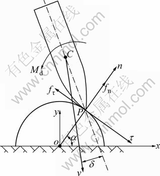
Fig. 1 Contact model for projectile impact on irregular barrier
2.2 Macroscopical relation for contact force versus contact time
The yaw-inducing problem would be very complicated if the factors, such as the strain rate, strain-hardening and thermal effect of material were considered for elasto-plastic dynamic contact. The rigid plastic theory of first-order had been always used to analyze the problem of plastic contact and applied in practical engineering. It was shown that it would result in a large value of error if the rigid plastic theory of first-order was used to analyze the problem of plastic contact, so the elastic effect must be taken into account [10]. The quasi-static elasto-plastic constitutive relation had been accurately used to analyze the problem like the contact with high impact velocity between projectile and irregular barrier for the sake of the complexity of the contact force versus contact displacement. In addition, the restitution coefficient was introduced to avoid the complicated local plastic displacement which was usually solved by of finite element method [11-12].
It was supposed that there were normal contact force fn and tangential contact force fτ produced at the contact piont between projectile and irregular barrier. According to contact theory of Hertz [13] and Ref. [11], the relation of contact force versus contact time could be given approximatively by
 (1)
(1)
and
 (2)
(2)
where  is the relative elastic
modulus,  is the shear modulus,
R* is the radius of equivalent relative curvature;  and
and  are the Poisson ratios of projectile and irregular barrier, respectively; Ep and Eb are the elastic moduli of projectile and irregular barrier, respectively; Gp and Gb are the shear moduli of projectile and irregular barrier, respectively;
  is the contact time during elastic phase; tep is the contact time during elasto-plastic phase; Tc is the total contact time; δn and δ are the normal displacement and tangential displacement, respectively; en and eτ are the normal restitution coefficient and tangential restitution coefficient, respectively, and they are the functions of geometrical characteristic, material property, impact attitude, impact velocity and strain rate [11]. The elastic problem is transformed to elasto-plastic problem by introducing the restitution coefficient into the contact model, train rate is taken into account for using Cowper and Symonds model which scales the yield stress with dynamic increase factor.
2.3 Expression of attack angle and angular velocity
On the basis of classical impact theory, momentum and angular momentum conservations in the impact plane of the system could be expressed as
 (3)
(3)
 (4)
(4)

 (5)
(5)
where Mp is the mass of projectile; vx and vy are the velocity components along x-axis direction and y-axis direction, respectively, as shown in Fig. 1; L0 is the length from the mass center to the top end for projectile; θ0 is the initial angle between velocity direction of mass center projectile and x-axis direction; δ0 is the initial attack angle.
Therefore, the attack angle δ and angular velocity ω of projectile after impact could be given respectively as

 (6)
(6)
 (7)
(7)
where μ is the dynamic friction coefficient between projectile and irregular barrier, which could be obtained from Ref. [14]; JC is the moment of inertia of the projectile within its impact plane.
3 Differential equation for projectile
The xoy-coordinate system was set up for the moment of projectile impact on target surface after it contacts with irregular barrier. As can be seen from Fig. 2, φ=π/2-θ, o is the mass center of projectile, with x-axis along horizontal direction, and y-axis along vertical direction. The motion equations of projectile oblique into the target shown in Fig. 3 could be given as
 (8)
(8)
 (9)
(9)
 (10)
(10)
where Fd and Ft are the normal force and tangential force by simplifying the resistance to the mass center of projectile during penetration;  is the angular acceleration; β=θ-δ, is the deflexion angle; θ is the angle
between velocity direction of mass center of projectile and x-axis direction. For  and dy/dt=vsinθ, the differential equations could be written as
 (11)
(11)
 (12)
(12)
Then, Eqs. (8) and (9) could be simplified as
 (13)
(13)
 (14)
(14)
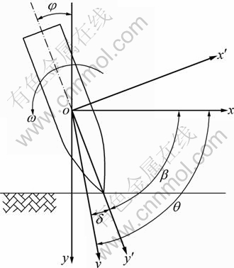
Fig. 2 Impact attitude of projectile
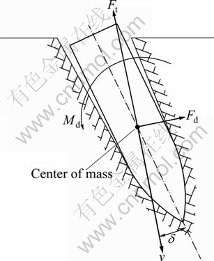
Fig. 3 Resistance for oblique penetration
As shown in Fig. 4, the velocity components of normal direction vn and tangential direction vτ on optional point of the nose of projectile were expressed respectively as [15]
 (15)
(15)
 (16)
(16)
where γ is the angle between meridional plane on optional point of the nose of projectile and impact plane.

Fig. 4 Velocity distribution on projectile nose
According to spherical cavity expansion theory and Coulomb law, the normal stress σn and tangential stress στ by considering the unsymmetrical resistance of target surface could be expressed as [16]
 (17)
(17)
 (18)
(18)
where β is the deflexion angle relative to normal target; A and B are the functions of projectile shape and material characteristic of target [16], respectively; v1,n and v2,n are the velocity components of upper/under surface on optional point of the nose of projectile, respectively. The resistances were given as
 (19)
(19)
 (20)
(20)
 (21)
(21)
where
 (22)
(22)
 (23)
(23)
 (24)
(24)
 (25)
(25)

 (26)
(26)

 (27)
(27)

 (28)
(28)

 (29)
(29)
Above equations could be simplified as
 (30)
(30)
 (31)
(31)
 (32)
(32)
The tangential resistance Ft and normal resistance Fd which are relative to velocity could be expressed as
 (33)
(33)
 (34)
(34)
The parameters could be detailed expressed as
 (35)
(35)
 (36)
(36)

 (37)
(37)
 (38)
(38)
 (39)
(39)
 (40)
(40)

 (41)
(41)
 (42)
(42)


 (43)
(43)


 (44)
(44)


 (45)
(45)

 (46)
(46)
where f is the half angle for the nose of projectile; KC is the unsymmetrical influencing coefficient [16]; lr is the length of the nose of projectile; l1 and l2 are the penetration length for upper and under projectile nose, respectively.
Based on above expressions, the following differential equations could be obtained

 (47)
(47)


 (48)
(48)
 (49)
(49)
 (50)
(50)
The motion trajectory of the nose of projectile could be expressed by the motion of mass center of projectile, and it could be expressed as
 (51)
(51)
 (52)
(52)
where Xh and Yh are the horizontal displacement and vertical displacement of the nose of projectile, respectively.
Solving the simultaneous equations from Eqs. (47)- (52) with initial conditions by means of four-order Runge-Kutta method, both the penetration depth Yh and the motion trajectory of the nose of projectile could be obtained.
4 Computation example
According to the data in Ref. [17], the material parameters of target are as follow: compressive strength of RPC with steel fiber volume ratio of 2.5% is fc= 145 MPa, shear strength  6.216 MPa, density ρ0= 2 800 kg/m3, and wave velocity for cracked RPC
  1 150 m/s. The material of irregular barrier consists of high strength steel fiber reinforced RPC of 250 MPa with diameter of 100 mm and elastic modulus of 59.5 GPa. A 4.44 kg semi armour-piercing steel projectile with a spherical nose radius of 228 mm, a length of 456 mm and a diameter of 57 mm is used. The referenced strain rate is 3.0×10² s-1 using Cowper and Symonds model. The theoretical results are shown in Fig. 5 for different cases.
It could be seen from Fig. 5(a) that, in the case of oblique impact, the penetration depth of projectile decreases with impact angle increasing. The attack angle of projectile influences the penetration depth greatly. When the attack angle increases, the penetration trajectory deflects and the penetration depth reduces obviously, as shown in Fig. 5(b). It is shown in Figs. 5(c) and (d) that, the penetration depth decreases with the angular velocity increasing. Furthermore, the higher the impact velocity, the more obvious the deflected trajectory. In addition, it is indicated that the influencing effectiveness of angular velocity on penetration depth of projectile increases with impact velocity increasing.
5 Comparison of theoretical results with test data
A penetration experiment was carried out to verify the accuracy of the theoretical formulation. A 4.44 kg semi armour-piercing steel projectile with an ogival nose radius of 228 mm, a length of 456 mm and a diameter of 57 mm, was fired at the targets at a distance about 50 m. The material of model projectile was 30CrMnSi with yield stress of 885 MPa and failure stress of 1 050 MPa. As shown in Fig. 6, the projectile impacts with approximately zero angle of attack (δ=0) and a velocity of 320-705 m/s, and the suppositional shoot point was the point with α=45° on the irregular barrier at the middle yaw-inducing layer. As shown in Fig. 7, Targets 1-2 were for penetration tests (projectile passed through target) and Targets 3-5 for perforation tests (projectile came to rest in the target).
In Table 1, the theoretical results and test data are presented. It is indicated that the values of theoretical deflexion angles and theoretical attack angles both decrease approximately linearly with impact velocities increasing, but the values of theoretical angular velocities increase approximately linearly with impact velocities increasing. For the penetration depths, the results show that the theoretical results are in good agreement with the test data for impact velocities lower than 505 m/s, but it is not satisfied for impact velocities higher than 505 m/s. Actually, the nose of projectile would be deformed or damaged badly with higher impact velocity, so the penetration trajectory is deflected and the penetration depth is reduced obviously. It is the essential reason that the theoretical penetration depth is usually larger than that of the experiment [17].
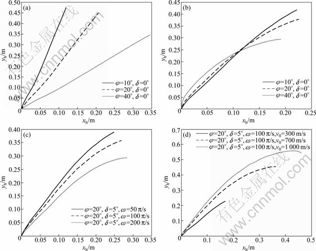
Fig. 5 Ballistic trajectory of projectile: (a) Ballistic trajector versus φ; (b) Ballistic trajectory versus δ; (c) Ballistic trajectory versus ω; (d) Ballistic trajectory versus v0
Fig. 6 Bursting layer and projectile before test: (a) Bursting layer; (b) Projectile
Fig. 7 Bursting layer after test: (a) v0=685 m/s; (b) v0=705 m/s; (c) v0=505 m/s; (d) v0=373 m/s; (e) v0=320 m/s
Table 1 Comparison of theoretical results with test data
6 Conclusions
1) Theoretical computations of penetration and perforation tests of bursting layer with irregular barriers on surface were carried out. The problem of projectile impact on irregular barrier is presented by introducing the restitution coefficient into the elastic contact model of Hertz. The differential equation for projectile oblique into target embodying effect of attack angle is given on the basis of spherical cavity expansion theory and solved by four-order Runge-Kutta method. Influences of penetration trajectory and penetration depth based on the impact angle, attack angle, angular valocity and impact velocity were investigated.
2) Theoretical computations show that the penetration depth decreases with angular velocity increasing. Furthermore, the higher impact velocity, the more obvious the deflected trajectory. The influencing effectiveness of angular velocity on penetration depth of projectile increases with the impact velocity increasing. The computation results show good agreement with test data for penetration depth with lower impact velocity. For higher impact velocity, the results are not satisfied since the nose of projectile is deformed or damaged badly, which is not considered for the computations.
3) For the contact model, the problem of nonlinear dynamic contact was simplified greatly, and the mechanics meaning of computation formula is clear. The computation method of penetration depth for yaw- inducing bursting layer with irregular barriers on surface impacted by projectile is given based on effect of attack angle. It is indicated that the computation method presented by considering macroscopy yaw-inducing effectiveness is synthetically credible, and it is significative for practical engineering application.
References
[1] SONG Li-ping, WANG Hua. Development of precisely guided penetration weapons in USA [J]. Winged Missiles Journal, 2000, (1): 40-44. (in Chinese)
[2] AUSTIM C F, HALSEY C C, CLODT R L. Protection systems development [R]. Tyndall Air Force Base, 1982.
[3] ROHANI B. Penetration of kinetic energy projectiles into rock-bubble/boulder overlays [R]. Waterways Experiment Station, 1987.
[4] GELMAN M D, RICHARD B N, ITO Y M. Impact of armor-piercing projectile into array of large caliber boulders [R]. Waterways Experiment Station, 1991.
[5] UNDERWOOD J M. Effectiveness of yaw-inducing deflection grids for defeating advanced penetrating weapons [R]. Air Force Civil Engineering Support Agency, 1995.
[6] ROHANI B. Shielding methodology for conventional kinetic energy weapons [R]. Waterways Experiment Station, 1987.
[7] CARGILE J D, CAMMINS T R. Effectiveness of yaw-inducing bar screens for defeating low length to diameter armor-piercing [R]. Waterways Experimental Station, 1992.
[8] WANG Ming-yang, LIU Xiao-bing, QIAN Qi-hu. An engineering calculation method for the depth of penetration of projectile in steel fiber reinforced concrete embedded with steel spheres [J]. Acta Armamentarii, 2002, 23(1): 14-18. (in Chinese)
[9] LIU Rui-chao, HE Man-chao, REN Hui-qi. Effect of attack angle on a projectile’s penetration [J]. Transactions of Beijing Institute of Technology, 2003, 23(1): 26-29. (in Chinese)
[10] WANG Ming-yang, QIAN Qi-hu. Studies on the dynamic properties for granular medium under stress wave [J]. Explosion and Shock Waves, 1996, 16(1): 11-20. (in Chinese)
[11] CHEN Wan-xiang, GUO Zhi-kun, QIAN Qi-hu.Yawing mechanism of projectile based on contact theory [J]. Journal of PLA University of Science and Technology, 2006, 7(5): 458-466. (in Chinese)
[12] THORNTON C. Coefficient of restitution for collinear collisions of elastic-perfectly plastic spheres [J]. ASME J Appl Mech, 1997, 64: 383-386.
[13] JOHNSON K L. Contact mechanics [M]. Cambridge: Cambridge University Press, 1985: 386-424.
[14] CHEN Da-nian, Al-Hassani S T S. Effective friction coefficient during particle impact on memtal [J]. Engineering Mechanics, 2004, 21(5): 172-177. (in Chinese)
[15] YIN Fang-lin, WANG Ming-yang, QIAN Qi-hu. Penetration depth of projectile oblique into target [J]. Explosion and Shock Waves, 1998, 18(1): 60-76. (in Chinese)
[16] WANG Ming-yang, RONG Xiao-li, QIAN Qi-hu. Calculation principle for penetration and perforation of projectile into rock [J]. Chinese Journal of Rock Mechanics and Engineering, 2003, 21(11): 1811-1816. (in Chinese)
[17] CHEN Wan-xiang, GUO Zhi-kun. Anti-penetration characteristics of RPC shelter plates with irregular barriers on surface [J]. Explosion and Shock Waves, 2010, 30(1): 51-57. (in Chinese)
(Edited by DENG Lü-xiang)
Foundation item: Project(20110490894) supported by the Postdoctoral Science Foundation of China; Project(50908228) supported by the National Natural Science Foundation of China; Project(51021001) supported by the Science Foundation for Creative Research Groups of China
Received date: 2011-06-14; Accepted date: 2011-09-27
Corresponding author: CHEN Wan-xiang, PhD; Tel: +86-25-80821045; E-mail: cwx_0806@sohu.com

