
J. Cent. South Univ. (2020) 27: 2148-2159
DOI: https://doi.org/10.1007/s11771-020-4437-4

Active earth pressure for subgrade retaining walls in cohesive backfills with tensile strength cut-off subjected to seepage effects
FU He-lin(傅鹤林)1, WANG Cheng-yang(王成洋)1, LI Huan(李寰)2
1. School of Civil Engineering, Central South University, Changsha 410075, China;
2. Department of Architecture and Civil Engineering, City University of Hongkong,Hongkong 999077, China
 Central South University Press and Springer-Verlag GmbH Germany, part of Springer Nature 2020
Abstract: The commonly used Mohr-Coulomb (M-C) failure condition has a limitation that it overestimates the tensile strength of cohesive soils. To overcome this limitation, the tensile strength cut-off was applied where the predicted tensile strength is reduced or eliminated. This work then presented a kinematical approach to evaluate the active earth pressure on subgrade retaining walls in cohesive backfills with saturated seepage effects. An effective rotational failure mechanism was constructed assuming an associative flow rule. The impact of seepage forces, whose distribution is described by a closed-form solution, was incorporated into the analysis. The thrust of active earth pressure was derived from the energy conservation equation, and an optimization program was then coded to obtain the most critical solution. Several sets of charts were produced to perform a parameter analysis. The results show that taking soil cohesion into account has a distinct beneficial influence on the stability of retaining walls, while seepage forces have an adverse effect. The active earth pressure increases when tensile strength cut-off is considered, and this increment is more noticeable under larger cohesion.
Key words: active earth pressure; seepage effect; subgrade retaining wall; tensile strength cut-off
Cite this article as: FU He-lin, WANG Cheng-yang, LI Huan. Active earth pressure for subgrade retaining walls in cohesive backfills with tensile strength cut-off subjected to seepage effects [J]. Journal of Central South University, 2020, 27(7): 2148-2159. DOI: https://doi.org/10.1007/s11771-020-4437-4.
1 Introduction
Retaining walls are commonly used in subgrade engineering [1-4]. A primary problem in retaining wall designs is to determine active earth pressure, which has been widely studied by many researchers [5-8]. One of major factors considered when designing such structures is water flow inside the backfill. It is well-recognized that saturated seepage has an adverse impact of increasing the inducing forces on the retaining wall. Therefore, it is necessary to build a suitable model to investigate the influence of seepage force on active earth pressure. So far, only a few studies have been performed. For example, a closed-form equation was derived by Barros [9] to characterize the profile of pore-water pressure, where a Coulomb- type formulation was applied to solve the active earth pressure with seepage effects. Benmebarek et al [10] presented a numerical simulation implemented in the (fast Lagrangian analysis of continua) FLAC software to determine the active and passive earth pressures with seepage effects. Using the same method in Ref. [9], Barros et al [11] presented a more general solution for inclined walls, where the boundary element method is utilized to obtain the profile of pore-water pressure.
However, despite the great contribution, the above studies are mainly limited to the basic assumption of cohesiveness backfills. Neglecting the soil cohesion will result in fairly conservative results and a large amount of structural construction wastes. ANDERSON et al [12] found that the existence of cohesion as small as 10 kPa can reduce the necessary support up to of 50%. Consequently, it is of vital practical significance to consider the effects of cohesion. In addition, many previous studies have used the simplified planar mechanism as the collapse surfaces. They ignored the fact that the actual failure surfaces are usually curved. Compared to the planar mechanism, the curved pattern (e.g. log-spiral mechanism) has been demonstrated to be much more realistic [1, 2]. In fact, because the curved mechanism can be degraded to the planar mechanism, the planar surface can be seen as a particular case of curved failure surfaces [13].
The M-C failure condition is typically used in soil mechanics, involving an effective angle of internal friction φ′ and effective cohesion c′. However, the tensile strength of cohesive soils (i.e., c′>0) is overestimated by the classical M-C criterion, resulting in an unrealistic result of earth pressure. In practice, the tensile resistance of most soils is quite unreliable and is usually affected by external factors [2]. As a consequence, the soil is usually treated as a material that is not resistant to tensile strength or has only a very low tensile strength. On account of this fact, eliminating tensile strength from the yield criterion was recommended by DRUCKER et al [14], while PAUL [15] proposed an approach of tension cut-off. This approach has been employed in many analyses of slope stability recently [16-19], where a non-linear segment is introduced in the criterion. According to several studies of slope stability involving tension cut-off, accounting for tension cut-off will observably reduce the slope stability [16-19]. This is in line with expectations and indicates that reduction or elimination in soil tensile strength results in more conservative results. As a consequence, detailed analysis is required on the influence of tensile strength cut-off on active earth pressure. There are two different ways to remove the effect of tensile strength. One way is to reconstruct the failure mechanism based on the modified failure criterion [17, 19], and the other is to introduce tension cracks forming part of the failure surface in a straight-forward manner [16, 18]. Both methods are effective, while the former is more common [17, 19] and is employed herein.
It was found that the contribution of tension cut-off may be encouraged by seepage forces in slope stability analyses [16-19]. It is a rather interesting topic to study the combined effects of seepage forces and tension cut-off on the active thrust, which has not yet been studied. This paper is dedicated to the study of active earth pressure under the effects of reducing or eliminating soil tensile strength in cohesive backfills subject to seepage forces. To fulfill this goal, the tension cut-off is adopted. Based on the associated normality rule, an effective rotational failure mechanism is built to calculate work rates. From the energy conservation equation, an explicit expression of the active thrust can be derived and the most critical result is obtained through optimization procedure. Several charts are given to perform parameter studies. The novelty of this work lies in the consideration of both effects of tension strength cut-off and seepage forces on active earth pressure.
2 Description of problem
As shown in Figure 1, the ground of the backfill is horizontal, and the soil-structure interface is vertical with height H. The structure is set to be long enough to allow the application of plane strain conditions. The water passes though the backfill steadily under the hydrostatic pressure with the water table located at the top. On the interface between the wall and the soil, an effective work drainage system is placed to take the water approaching it completely away from the system, so that the water pressure can be neglected on this interface. The impervious layer is located at the base behind the retaining wall, which keeps water out of the base. The cohesive backfill is characterized by the modified M-C criterion suggested by MICHALOWSKI [17], where the tensile strength is partially or completely cut-off. The backfills obey the flow rule associated with the modification.
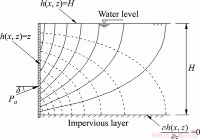
Figure 1 Schematic diagram of anglyzed problem and flow net
3 Distribution of pore-water pressure
The seepage forces are caused by the changes of the hydraulic conditions. Four different types of drawdown were categorized by VIRATJANDR et al [20]. The complete rapid drawdown is concluded to be the most unfavorable condition and it is taken into account herein. SAADA et al [21] and PAN et al [22] also studied this hydraulic condition in 2D and 3D cases, respectively. Figure 1 is a schematic diagram of seepage problem, where the water table is placed at the top of the backfill surface. For simplicity of charity, a Cartesian coordinate system with the wall toe as origin is introduced. Then, within the boundaries of x≥0, 0≤z≤H, a steady flow condition is considered. The influence of seepage forces can be included in the analysis by adding an additional term of work rate done by seepage forces. For this purpose, the distribution of pore-water pressure needs to be determined first. The steady flow continuity condition is expressed through the Laplace differential equation given by [9, 11, 23]:
 (1)
(1)
where h(x, z) represents the total head of water. For the case of vertical boundary, h(x, z) can be expressed by Fourier series expansion as follows:
 (2)
(2)
where Am(x) are the functions deduced according to the Laplace equation and the boundary conditions. The following boundary conditions are required to satisfy:
 (3)
(3)
By substituting Eq. (2) into Eq. (1) and considering the above boundary conditions, a general function of Am(x) is obtained as follows:
 (4)
(4)
Consequently, the total water head h(x, z) can be derived:
 (5)
(5)
where M=(2m+1)π/2. Using this solution, the flow net can be drawn, as shown in Figure 1. Then, the variation of pore-water pressure in space is deduced as:
 (6)
(6)
where γw refers to the water unit weight.
4 Tensile strength cut-off
The M-C criterion for saturated soil shows a linear characteristic on  stress plane. It can be found in Figure 2(a), without consideration of tension cut-off, the apex O reflects the triaxial tensile strength in the envelop,
  while the position of point P determines the uniaxial tensile strength,
 The existence of the portion of tensile regime in M-C strength criterion will logically result in an overestimation of the soil tensile strength. To address this drawback, it is necessary to limit or eliminate the soil tensile strength. According to the recommendations of MICHALOWSKI [16, 17], a non-linear part was introduced into the strength criterion, which is formed by a stress circle in the tensile regime where both the partially and fully tension cut-off can be accounted for. Figure 2(b) illustrates the case where the tensile strength is partially reduced.
Let us introduce a new stress circle C1 to denote the reduced tensile strength ft and then draw a new circle C2 tangent to the M-C criterion line and circle C1 at points S and P, respectively. The M-C criterion is modified through replacing the OS section with the PS section, ensuring that the value of ft is always no smaller than the corresponding normal stress in the modified envelope. Figure 2(c) illustrates the case where the tensile strength is completely eliminated, and similarly, through replacing the OS section with the PS section, the failure criterion is modified. For simplicity of clarifying, a dimensionless coefficient μ (0≤μ≤1) is adopted to characterize the actual uniaxial tensile strength, which is given by:
 (7)
(7)
As shown in Eq. (7), coefficient μ=1 corresponds to soils with full tensile strength (Figure 2(a)); 0<μ<1 corresponds to soils with reduced tensile strength (Figure 2(b)); and μ=0 corresponds to soils with zero tensile strength (Figure 2(c)).

Figure 2 Failure envelope modified with tensile strength cut-off for soils:
The expression used to evaluate the dissipation work rate per unit area obeys
 (8)
(8)
where v refers to the modulus of the velocity vector v; η refers to the rupture angle; ft and fc denote the tensile and compressive strengths under one- dimensional condition, respectively. This is a general formula for all cases, no matter whether the tension cut-off is involved.
By combining Eq. (7) and 
 Eq. (8) can be rearranged as follows:
 (9)
(9)
From Eq. (9), it is found that even if the coefficient μ=0, energy still dissipates along the collapse surface. In addition, Eq. (9) will degenerate into the conventional expression for calculation of rate of internal energy dissipation when  which reads as:
 (10)
(10)
5 Formulation of problem
5.1 Kinematic approach of limit analysis
An effective and widely used tool to analyze stability problems in geotechnical engineering is the kinematic limit analysis method [1-3, 24-36]. In the kinematic approach, the loads estimated from the energy conservation equation in any admissible velocity field are always no less than the actual failure loads. The sign of the force of the retaining wall is taken as negative due to the fact that the wall is resistant to the collapse of the soil mass. Therefore, the kinematic approach produces lower bounds of the actual result of active earth pressure. It is important to note that the effectiveness of the associated flow rule is implied in the aforementioned valid velocity field, which can be expressed as:
 (11)
(11)
where vt and vn refer to the normal and tangent velocities, respectively.
5.2 Rotational failure mechanism
According to a large number of previous studies, the rotational failure mechanisms yield the most critical solutions [1, 2]. More commonly, a log-spiral mechanism is applied. However, with considering the tension cut-off, the failure mechanism should be adjusted accordingly. An effective failure mechanism associated with the modified criterion is established in this section. Figure 3 is the sketch diagram of the rotational mechanism, in which the failure block rotates rigidly around the center point O and the boundaries are limited by EB, BC, CD and DE. The thin shear zone BCD where soil deformation occurs is assumed to be the failure surface. Considering the fact that the tensile regions commonly exist at the top of the backfill, the non-linear section of the strength curve controls the deformation in the upper region (BC), while the linear section controls the lower region (CD). The positions of points B and C are not known in advance but are determined based on optimization. A situation may occur where both points B and C coincide with point A as the wall geometry and soil properties change, and the result will degenerate to the classical solution.

Figure 3 Schetch of failure mechanism with tensile strength cut-off
The following geometric relations are derived according to Figure 3:
 (12)
(12)
 (13)
(13)
where L is the length of segment AE.
Based on Eq. (11), Figure 4 illustrates an infinitesimal element of section BC with rupture angle η. From the geometry of the infinitesimal element, a differential equation is obtained as follows:
 (14)
(14)

Figure 4 Illustration of infinitesimal element of collapse surface with rupture angle η
An explicit expression of section BC can be derived by solving Eq. (12):
 (15)
(15)
where θm and rm are the initial distance and angle of the collapse block, respectively. Equation (15) will degenerate to be the common equation of the log-spiral when  On account of tensile strength cur-off, the rupture angle η changes with the variation of θ [17, 19]. The value of η is equal to
  at θC to keep the failure surface smooth at point C and reaches the maximum at θB. It is necessary to determine the function of η(θ) before determining the geometry of section BC. According to MICHALOWSKI [17], it is usually considered that the function η(θ) is linear with the variation of θ, which can be expressed as:
 (16)
(16)
Then the log-spiral DC and modified curve CB can be written as:
 (17)
(17)
The rotating mechanism can be determined entirely from geometric variables θ0, θm, θtc, θh and ηm. Since the curves AC and BC intersect at point C, it yields:
 (18)
(18)
Only four of the five angles are independent, because ηm can be given by the other four variables by arranging Eq. (18), namely:
 (19)
(19)
The equation is implicit and requires numerical calculations. As a consequence, these four independent variables θ0, θm, θh and θtc are selected as the optimization object to obtain the most critical solution.
5.3 Calculation of work rate balance equation
The seepage force is included by adding an additional work rate term in this analysis. As a consequence, the external work includes work due to soil weight, wall reaction and seepage forces. And the internal work caused by soil cohesion dissipates along the failure surface. Therefore, the energy conservation equation is written as:
 (20)
(20)
where Wγ, Wu and WPa refer to the rate of work generated by soil weight, pore-water pressure u, reaction of the active thrust Pa, respectively;γ denotes the saturated soil unit weight; D refers to the internal dissipated work rate. The detailed derivations for the above work rates are shown subsequently.
Wγ is decomposed into the rate of work of ADE, Wγ-ADE and that of area ABC, Wγ-ABC. The method of calculating Wγ-ADE and Wγ-ABC has been presented by CHEN [1] and MICHALOWSKI [17], respectively. Therefore,

 (21)
(21)
where ω denotes the angular velocity around point O, and f1-f3 and t1-t3 are dimensionless functions as follows:

 (22)
(22)
 (23)
(23)
 (24)
(24)

 (25)
(25)
 (26)
(26)
 (27)
(27)
An additional external rate is introduced to include the effect of seepage forces. The rate of work generated by pore-water pressure is [20, 21, 37, 38]:
 (28)
(28)
where V is volume and S the boundary surface of the collapse block, respectively;  refers to the principal strain rate;
  refers to the unit outward normal vector of the boundary surface; vi refers to the velocity vector of the rotational mechanism. Since the collapse block is usually considered to rotate rigidly without volume deforming, the part of the work rate due to volumetric strain in Eq. (28) is zero. Based on the obtained profile of pore-water pressure, this work rate is obtained as:
 (29)
(29)
 (30)
(30)
 (31)
(31)
where f4 and f5 denote 2 dimensionless parameters, and x, z may be given by:
 (32)
(32)
The position of thrust action is usually assumed to be one-third of the wall height from the toe of wall [5, 6, 13, 39]. As shown in Figure 1, the angle between the thrust and the outer normal of the wall surface is denoted as δ, which is also known as friction angle of the wall. The work rate of the thrust can be obtained as:
 (33)
(33)
 (34)
(34)
where f6 represents a dimensionless parameter.
The rate of internal energy dissipation can also be divided into two portions: the internal dissipated rate along the log-spiral CD, denoted as DCD and the rate along the modified surface BC, denoted as DBC. DBC can be calculated according to Eq. (9), while DCD can be calculated according to Eq. (10). The sum of these two parts of dissipation rate is:
 (35)
(35)

 (36)
(36)
 (37)
(37)
where f7 and f8 denote 2 dimensionless parameters.
5.4 Active earth pressure and optimization
The explicit equation of Pa can be derived by combining Eqs. (20), (21), (29), (33) and (35), which takes the following form:

 (38)
(38)
When points B and C coincide at point A on the collapse surface, the solution will degenerate into a traditional solution using the M-C criterion. For this case, Eq. (38) derived based on the tension cut-off still applies.
Since the actual solution of Pa is not smaller than that from the kinematic method, an optimization program with respect to four independent variables is written in MATLAB to find the most critical outcome among all possible outcomes of active earth pressure. The exhaustive algorithm is employed to roughly locate the initial point. Based on it, a more advanced function in MATLAB, the sequential quadratic programming, is applied for locating the optimal point. The optimization scheme is performed under the following constraints:
 (39)
(39)
A dimensionless coefficient of the following form is introduced for analysis purposes [13, 32, 33]:
 (40)
(40)
where Ka refers to the active earth pressure coefficient.
6 Discussion
In this section, the influence of several factors on the results of the active thrust is analyzed. The outcomes with considering tension cut-off as well as under the M-C criterion are presented in figures. These figures will provide a reference for geotechnical engineering. Noted that γw/γ=0.5 is adopted in this work.
In Figures 5-7, the results of Ka versus c′/γH for the case of no-flow and the case of seepage effects under conditions of  1/2, 1 are presented, with φ′ varying from 15° to 35°. It can be found from the outcomes that considering the existence of soil cohesion can greatly reduce Ka. For example, for
  φ′=30°, even in the case of fully tensile strength cut-off, Ka takes a value of 0 for c′/γH=0.2, 0.126 for c′/γH=0.1 and 0.333 for no cohesion. More specifically, when H=5 m and γ=20 kN/m3, compared with the case of no cohesion, a small cohesion of 10 kPa can greatly decrease the necessary thrust by 62.2%, and no support is required when cohesion increases to 20 kPa. For the case without tension cut-off, the impact of soil cohesion is even more obvious. In addition, considering seepage forces will significantly increase the instability of the soil-wall system, indicating more support is required. Taking an example, in Figure 5 with φ=30° and c′/γH=0.1 for the case of tension cut-off, Ka increases by 73.0% from 0.126 for the no-flow case to 0.218 for the case with seepage effects.
In addition, the outcomes of Ka with considering tension cut-off are found to be not smaller than those from M-C criterion. The Ka curves with tension cut-off are almost overlapped with that by the M-C criterion at a relatively small c′/γH. As c′/γH grows, the differences between these two kinds of curves become increasingly apparent. This trend implies that the influence of the tensile strength cut-off is notable for soils with large cohesion, but negligible for soils with small cohesion (e.g., sandy soils). Another interesting finding is that under the seepage forces, the impact of tension cut-off is observably enlarged. The reason is that the introduction of the tension cut-off causes the rupture angle to increase, which results in the increase of the work done by the seepage force.

Figure 5 Ka versus c′/γH with different φ′ values at δ/φ′=0:

Figure 6 Ka versus c′/γH with different φ′ values at δ/φ′=1/2:
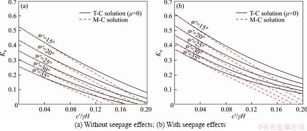
Figure 7 Ka versus c′/γH with different φ′ values at δ/φ′=1:
Figure 8 illustrates the influence of coefficient μ, in which the results of Ka versus c′/γH for various μ values for the case with no-flow and the case with seepage effects are given. As shown in Figure 8, for relatively low cohesion values, the effect of different μ values on the necessary thrust is negligible. But for higher cohesions, the impact of μ becomes more pronounced. Similarly, the effect of different μ values is more apparent under seepage forces. Furthermore, it is found that the impact of μ is noticeable only in the case of small μ values, as μ grows, the impact becomes less noticeable and when the value of μ exceeds a certain high value (e.g., 0.5), the results of critical Ka of different μ tend to the same. For example, the Ka curves for μ=0.5 and 1 are overlapped in the absence of seepage effects, and even including the influence of seepage forces, the difference between them is still small enough to be neglected.
The failure surfaces for different cohesions in the no-flow case and the case with seepage effects are presented in Figure 9, corresponding to φ′=25°, and δ/φ′=1/2. The failure surface obtained by M-C criterion is drawn with dashed lines. The failure surface using the modified criterion that eliminates the tensile strength is labeled BCD, where the BC portion is determined by the non-linear segment PS of the modified criterion in Figure 2(c) and the CD portion determined by linear segment of the modified criterion is part of log-spiral AD. From the comparison of Figures 9(a) and (b) and the comparison of Figures 9(c) and (d), it can be observed that in the entire failure surface BCD, the proportion of the modified portion CD for c′/γH=0.2 is distinctly larger than that for c′/γH=0.1. Furthermore, as shown in Figures 9(a) and (c), and Figures 9(b) and (d), the proportion of portion CD for the no-flow case is smaller than that under the seepage forces. This is the reason why the influence of tension cut-off is more pronounced when cohesion is larger and seepage forces are considered.
7 Conclusions
1) This work presented a kinematic method for evaluating the active earth pressure acting on vertical retaining walls under the combined effect of tension cut-off and seepage forces. By introducing a non-linear function to the original M-C failure criterion, the tension strength cut-off is applied. The influence of seepage forces, whose distribution was calculated from an analytical solution, was considered in the analysis by including an addition work rate term.
2) Based on an effective modified failure mechanism, the rates of external forces and internal energy dissipation were calculated, respectively. Then an explicit expression of the active thrust was derived based on the energy conservation equation. The most critical outcome was sought through optimization. Charts of selected parameters were presented to perform a sensitivity analysis. The novelty of this work is reflected in establishing an evaluation method for the active earth pressure with tension cut-off in a cohesive backfill affected by seepage forces.
3) From this work, it is found the active earth pressure coefficient is strongly influenced by the seepage forces, soil properties and the selected failure criterion. The existence of cohesion can significantly save the cost of retaining structures, while more support is needed to stabilize the wall under the influence of the seepage force.

Figure 8 Ka versus c′/γH with different μ values at δ/φ′=0:

Figure 9 Failure surfaces of retained soils with φ′=25° and δ/φ′=1/2:
4) The sensitivity of including tension cut-off is studied as well. In cohesive soils, reducing or eliminating the tensile strength will result in a greater outcome of the active thrust than the outcome from the traditional M-C condition. The influence of tension cut-off is more obvious as the soil cohesion increases, and this influence is even more pronounced with the effect of seepage forces considered.
References
[1] Chen W F. Limit analysis and soil plasticity [M]. Amsterdam: Elsevier, 1975.
[2] ZHANG B, MA Z Y, WANG X, ZHANG J S, PENG W Q. Reliability analysis of anti-seismic stability of 3D pressurized tunnel faces by response surfaces method [J]. Geomechanics and Engineering, 2020, 20(1): 43-54. DOI: 10.12989/gae.2020.20.1.043.
[3] ZHANG D B, LIU Z Z, ZHANG J H. A new failure mechanism for deep cavity and upper bound solution of supporting pressure [J]. Journal of Central South University, 2017, 24(9): 2082-2091. DOI: 10.1007/s11771-017-3617-3.
[4] Paik K H, Salgado R. Estimation of active earth pressure against rigid retaining walls considering arching effects [J]. Géotechnique, 2003, 53(7): 643-654. DOI: 10.1680/geot.2003.53.7.643.
[5] Li Z W, Yang X L. Active earth pressure for retaining structures in cohesive backfills with tensile strength cut-off [J]. Computers and Geotechnics, 2019, 110: 242-250. DOI: 10.1016/j.compgeo.2019.02.023.
[6] Li Z W, YANG X L. Active earth pressure from unsaturated soils with different water levels [J]. International Journal of Geomechanics, 2018, 19(7): 06019013. DOI: 10.1061/ (ASCE)GM.1943-5622.0001471.
[7] Li Z W, Yang X L, Li Y X. Active earth pressure coefficients based on a 3D rotational mechanism [J]. Computers and Geotechnics, 2019, 112: 342-349. DOI: 10.1016/j.compgeo.2019.05.005.
[8] Zhang D B, Jiang Y, Yang X L. Estimation of 3D active earth pressure under nonlinear strength condition [J]. Geomechanics and Engineering, 2019, 17(6): 515-525. DOI: 10.12989/gae.2019.17.6.515.
[9] Barros P L A. A Coulomb-type solution for active earth thrust with seepage [J]. Géotechnique, 2006, 56(3): 159-164. DOI: 10.1680/geot.2006.56.3.159.
[10] Benmebarek N, Benmebarek S, Kastner R, Soubra A H. Passive and active earth pressures in the presence of groundwater flow [J]. Géotechnique, 2006, 56(3): 149-158. DOI: 10.1680/geot.2006.56.3.149.
[11] Barros P L A, Santos P J. Coefficients of active earth pressure with seepage effect [J]. Canadian Geotechnical Journal, 2012, 49(6): 651-658. DOI: 10.1139/t2012-020.
[12] Anderson D G, Martin G R, Lam I P, Wang J N. Seismic analysis and design of retaining walls, buried structures, slopes, and embankments [M]. Washington, DC: The National Academies Press, 2008.
[13] Vahedifard F, Leshchinsky B A, Mortezaei K, Lu N. Active earth pressures for unsaturated retaining structures [J]. Journal of Geotechnical and Geoenvironmental Engineering, 2015, 141(11): 04015048. DOI: 10.1061/(ASCE)GT.1943-5606.0001356.
[14] Drucker D C, Prager W. Soil mechanics and plastic analysis or limit design [J]. Quarterly of Applied Mathematics, 1952, 10(2): 157-165.
[15] Paul B. A modification of the Coulomb-Mohr theory of fracture [J]. Journal of Applied Mechanics, 1961, 28(2): 259-268.
[16] Michalowski R L. Stability assessment of slopes with cracks using limit analysis [J]. Canadian Geotechnical Journal, 2013, 50(10): 1011-1021. DOI: 10.1139/cgj-2012- 0448.
[17] Michalowski R L. Stability of intact slopes with tensile strength cut-off [J]. Géotechnique, 2017, 67(8): 720-727. DOI: 10.1680/jgeot.16.P.037.
[18] Abd A H, Utili S. Design of geosynthetic-reinforced slopes in cohesive backfills [J]. Geotextiles and Geomembranes, 2017, 45(6): 627-641. DOI: 10.1016/ j.geotexmem.2017.08.004.
[19] Park D, Michalowski R L. Three-dimensional stability analysis of slopes in hard soil/soft rock with tensile strength cut-off [J]. Engineering Geology, 2017, 229: 73-84. DOI: 10.1016/j.enggeo.2017.09.018.
[20] Viratjandr C, Michalowski R L. Limit analysis of submerged slopes subjected to water drawdown [J]. Canadian Geotechnical Journal, 2006, 43(8): 802-814. DOI: 10.1139/t06-042.
[21] Saada Z, Maghous S, Garnier D. Stability analysis of rock slopes subjected to seepage forces using the modified Hoek-Brown criterion [J]. International Journal of Rock Mechanics and Mining Sciences, 2012, 55: 45-54. DOI: 10.1016/j.ijrmms.2012.06.010.
[22] Pan Q J, Xu J S, Dias D. Three-dimensional stability of a slope subjected to seepage forces [J]. International Journal of Geomechanics, 2017, 17(8): 04017035. DOI: 10.1061/ (ASCE)GM.1943-5622.0000913.
[23] Harr M E. Groundwater and seepage [M]. New York: McGraw-Hill, 1962.
[24] ZHANG D B, ZHANG B. Stability analysis of the pressurized 3D tunnel face in anisotropic and nonhomogeneous soils [J]. International Journal of Geomechanics, 2020, 20(4): 04020018. DOI: 10.1061/ (ASCE)GM.1943-5622.0001635.
[25] YANG X L, YIN J H. Upper bound solution for ultimate bearing capacity with a modified Hoek-Brown failure criterion [J]. International Journal of Rock Mechanics and Mining Sciences, 2005, 42(4): 550-560. DOI: 10.1016/j.ijrmms.2005.03.002.
[26] YANG X L. Seismic bearing capacity of a strip footing on rock slopes [J]. Canadian Geotechnical Journal, 2009, 46(8): 943-954. DOI: 10.1139/T09-038.
[27] YANG X L, YIN J H. Slope equivalent Mohr-Coulomb strength parameters for rock masses satisfying the Hoek-Brown criterion [J]. Rock Mechanics and Rock Engineering, 2010, 39(4): 505-511. DOI: 10.1007/s00603- 009-0044-2.
[28] YANG X L, HUANG F. Collapse mechanism of shallow tunnel based on nonlinear Hoek-Brown failure criterion [J]. Tunnelling and Underground Space Technology, 2011, 26(6): 686-691. DOI: 10.1016/j.tust.2011.05.008.
[29] YANG X L, HUANG F. Three-dimensional failure mechanism of a rectangular cavity in a Hoek-Brown rock medium [J]. International Journal of Rock Mechanics and Mining Sciences, 2013, 61: 189-195. DOI: 10.1016/ j.ijrmms.2013.02.014.
[30] HUANG F, YANG X L. Upper bound limit analysis of collapse shape for circular tunnel subjected to pore pressure based on the Hoek-Brown failure criterion [J]. Tunnelling and Underground Space Technology, 2011, 26(5): 614-618. DOI: 10.1016/j.tust.2011.04.002.
[31] Zhang J H, Wang W J, Zhang D B, Zhang B, Meng F. Safe range of retaining pressure for three-dimensional face of pressurized tunnels based on limit analysis and reliability method [J]. KSCE Journal of Civil Engineering, 2018, 22(11): 4645-4656. DOI: 10.1007/ s12205-017-0619-5.
[32] Zhang J H, Wang W J, Zhang B, Zhang D B. Upper bound analysis for collapse failure of shield tunnel face excavated in unsaturated soils considering steady vertical flow [J]. Mathematical Problems in Engineering, 2019: 2145616. DOI: 10.1155/2019/2145616.
[33] ZHANG J H, ZHANG B. Reliability analysis for seismic stability of tunnel faces in soft rock masses based on a 3D stochastic collapse model [J]. Journal of Central South University, 2019, 26(7): 1706-1718. DOI: 10.1007/s11771- 019-4127-2.
[34] Li T Z, Yang X L. Stability of plane strain tunnel headings in soils with tensile strength cut-off [J]. Tunnelling and Underground Space Technology, 2020, 95: 103138. DOI: 10.1016/j.tust.2019.103138.
[35] Huang F, Zhang M, Wang F, Ling T H, Yang X L. The failure mechanism of surrounding rock around an existing shield tunnel induced by an adjacent excavation [J]. Computers and Geotechnics, 2020, 117: 103236. DOI: 10.1016/j.compgeo.2019.103236.
[36] Li Z W, Yang X L, Li T Z. Static and seismic stability assessment of 3D slopes with cracks [J]. Engineering Geology, 2020, 265: 105450. DOI: 10.1016/j.enggeo. 2019.105450.
[37] Pan Q J, Dias D. The effect of pore water pressure on tunnel face stability [J]. International Journal for Numerical and Analytical Methods in Geomechanics, 2016, 40(15): 2123-2136. DOI: 10.1002/nag.2528.
[38] XU J S, PAN Q J, YANG X L, LI W T. Stability charts for rock slopes subjected to water drawdown based on the modified nonlinear Hoek-Brown failure criterion [J]. International Journal of Geomechanics, 2018, 18(1): 04017133. DOI: 10.1061/(ASCE)GM.1943-5622.0001039.
[39] Vieira C S, de Lurdes Lopes M, Caldeira L M. Earth pressure coefficients for design of geosynthetic reinforced soil structures [J]. Geotextiles and Geomembranes, 2011, 29(5): 491-501. DOI: 10.1016/j.geotexmem.2011.04. 003/.
(Edited by ZHENG Yu-tong)
中文导读
考虑回填黏土抗拉强度截断及渗流效应的路基挡土墙主动土压力计算
摘要:用于表征土体强度的莫尔-库仑破坏准则的局限性在于它高估了大多数土体的抗拉强度。为了克服不足,本文采用抗拉强度截断概念对莫尔-库仑破坏准则进行了修正,降低或消除土体中的抗拉强度。在此基础上,基于极限分析上限定理,建立了在饱和渗流作用下回填黏土路基挡土墙的主动土压力计算模型。根据关联流动规则,构造了一个有效的旋转破坏模式,并将饱和渗流引入到破坏模式中,根据能量守恒方程,推导了主动土压力合力的显式表达式。借助最优化程序获得了目标函数的最优上限解,同时给出了一系列图以便工程应用。结果表明,土体黏聚力显著有利于挡土墙的稳定性,而渗流力则具有不利影响。考虑土体抗拉强度截断会明显降低主动土压力,特别是在黏聚力较大的情况下,其抗拉强度截断效果更为明显。
关键词:路基挡土墙;抗拉强度截断;主动土压力;渗流效应
Foundation item: Projects(51538009, 51674115, 51804113) supported by the National Natural Science Foundation of China
Received date: 2020-03-25; Accepted date: 2020-04-16
Corresponding author: WANG Cheng-yang, PhD Candidate; Tel: +86-15616258764; E-mail: wangchengy@csu.edu.cn; ORCID: 0000- 0001-8956-0829

