Trans. Nonferrous Met. Soc. China 28(2018) 748-756
Direct active soldering of Al0.3CrFe1.5MnNi0.5 high entropy alloy to 6061-Al using Sn-Ag-Ti active solder
L. C. TSAO1, S. Y. CHANG2, Y. C. YU1
1. Department of Materials Engineering, National Pingtung University of Science & Technology, Neipu, Pingtung 91201, China;
2. Department of Mechanical Engineering, National Yunlin University of Science & Technology, Touliu, Yunlin 64002, China
Received 12 January 2017; accepted 4 April 2017
Abstract: Al0.3CrFe1.5MnNi0.5 high entropy alloys (HEA) have special properties. The microstructures and shear strengths of HEA/HEA and HEA/6061-Al joints were determined after direct active soldering (DAS) in air with Sn3.5Ag4Ti active filler at 250 ��C for 60 s. The results showed that the diffusion of all alloying elements of the HEA alloy was sluggish in the joint area. The joint strengths of HEA/HEA and HEA/6061-Al samples, as analyzed by shear testing, were (14.20��1.63) and (15.70��1.35) MPa, respectively. Observation of the fracture section showed that the HEA/6061-Al soldered joints presented obvious semi-brittle fracture characteristics.
Key words: high entropy alloy; Sn3.5Ag4Ti active filler; Al0.3CrFe1.5MnNi0.5; direct active soldering
1 Introduction
As various application fields such as energy, aerospace, transportation, and manufacturing advance, they present new demands on materials. New materials are able to meet new demands for high-end applications, such as excellent mechanical strength, creep strength, and thermal resistance [1,2].
In 1995, a breakthrough in the conventional concept of alloy design, called ��high entropy alloys (HEAs)��, was developed [3]. HEAs are composed of n major alloying elements with an equimolar or near-equimolar composition ratio, independent of the ��base element�� concept [4,5]. Presently, HEAs are being increasingly studied and possess special properties [6-11], such as high strength/hardness, outstanding wear resistance, exceptional high-temperature strength, good structural stability, and good resistance to corrosion and oxidation. YEH et al [12,13] reported that CuCoNiCrAl0.5Fe and AlCoCrCuFeNi alloys exhibiting very high hardness vary widely depending on the contents of the components. These alloys display simple BCC and/or FCC solid solution structures. TSAO et al [6] reported that age hardening is apparently accompanied by the formation of both NiAl and ��-phase in the matrix dendrites during Al0.3CrFe1.5MnNi0.5 alloy aging. The slow kinetics in cast HEA allows a readily attainable supersaturated state and nano-sized precipitates [14,15], which contribute to the excellent performance of HEA coatings as diffusion barriers [16,17] and precision resistors [18].
These brittle, non-metallic materials exert poor wettability when Sn solder is used. Therefore, detailed investigations have been conducted using the newly developed ��direct active soldering (DAS)�� method for many applications [19-21].  et al [21] reported that non-metallic materials such as Al2O3, SiO2, Si, and C (graphite) reduce the wetting angle when Sn solder is alloyed with active Ti element. CHANG et al [22] joined ZnS-SiO2/Cu by using Ti-active Sn3.5Ag4Ti filler, and the result was satisfactory. TSAO [23,24] reported that trace amounts of rare earth elements affect the interfacial reactions at Sn-Ag-Ti system/MAO-TiO2 interfaces, and Ag3Sn nanoparticles adsorb at the solder/MAO-TiO2 interfaces. QU et al [25] studied the mechanical property and the microstructure of Cu/1Cr18Ni9Ti soldered joint using SnAgTi solder. TSAO et al [26] used Sn-Ag-Ti active solder to bond a Si/Al heat sink and an Al-Gr composite/6061-Al [27] at 250 ��C in air. CHENG et al [28] found that Ti is largely segregated at the Si/active solder interface. However, no research has focused on low temperature HEA/Al bonding using the DAS method.
The purpose of this investigation was to study the joining of HEA/HEA and HEA/6061-Al with SAT active filler by DAS method. The microstructure interfaces, shear strength, and fracture were discussed in detail.
2 Experimental
2.1 Base material
A high entropy alloy (HEA), Al0.3CrFe1.5MnNi0.5, was prepared by vacuum arc melter using a current of 300 A in a water-cooled copper hearth under a pure Ar gas atmosphere, as shown in Fig. 1 [6]. The HEA alloy was repetitively melted and solidified with turning of the solidified ingots so as to obtain a completely alloyed state. The alloy was melted and chill cast in a copper mold to form square ingots of 8 mm �� 10 mm �� 20 mm. The chemical composition of the HEA alloy was analyzed with an inductively coupled plasma-atomic emission spectrometer (ICP-AES) device, and the results are listed in Table 1. The material used in this work was Sn3.5Ag4Ti (SAT) active solder plate containing trace amount of Ce element. Both the manufacturing process and the chemical composition (mass fraction, %) analysis are explained in a previous work [29]. The base metals were annealed plates of commercial 6061-Al alloy (Al sample, mass fraction: 0.28% Cu, 0.61% Si, 1.02% Mg, 0.20% Cr, and the balance Al).
2.2 Active soldering
Before direct active soldering, all samples (e.g., HEA and Al) were polished using silicon carbide grinding paper to 1200 grade, degreased in acetone, and then cleaned with alcohol. The joining process was performed on an electric hotplate with thermostatic control in an atmosphere of air. Prior to the joining, the Al and HEA were preheated to 250 ��C using the hotplate system. The hotplate system was calibrated until the temperature was steady. The temperature of the bond surfaces was measured with a K-type thermocouple. The SAT active filler was then set on the bond surfaces of the Al and HEA sample (10 mm �� 10 mm). After the molten active filler was agitated for 60 s by ultrasonic vibration so that the liquid filler would wet on the sample surfaces, the Al sample was placed on the HEA sample. After that, the joints were held firmly in place (pressure of 15 KPa) and cooled down to room temperature at a rate of 10 ��C/min, leading to the solidification of the molten active filler.
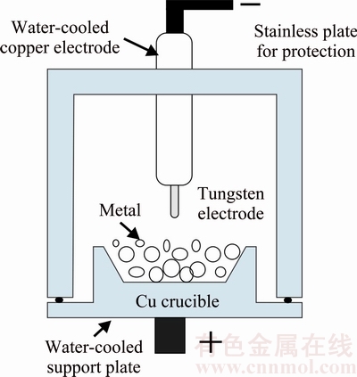
Fig. 1 Schematic diagram of arc melting method [6]
2.3 Analysis
The geometries of the active soldered samples subjected to shear testing are demonstrated in Fig. 2 [24]. The effective joint area was about 10 mm �� 10 mm. All shear experiments of sandwich-bonded samples were carried out on an MTS Tytron 250 testing machine under a constant strain rate of about 1.0 �� 10-2 s-1.
The microstructures of joined samples were examined by optical microscopy (OM, AXIO Scope A1, ZEISS) and scanning electron microscopy (SEM, S-3000H, Hitachi Co., Japan). Energy dispersive X-ray spectroscopy (EDS) was also used to determine the elemental compositions of selected sites.
3 Results and discussion
3.1 Characterization of base material
Figure 3 presents the XRD pattern and the microstructure of as-cast HEA sample. It is found that the formation of both the amorphous characteristic (broad diffraction peak, 2q=25��-35��) and the low intensity crystalline peaks occur [3,4]. CUO et al [30] studied the effects of these parameters on the phase formation of HEA. The atomic size polydispersity (d) is the most critical parameter that distinguishes the mation of solid solutions and the amorphous phase. Solid solutions and the amorphous phase form below and above a critical d of ~0.065, respectively. In addition, the crystal structure of as-cast HEA sample consisted of only BCC and FCC solid-solution phases; i.e., no intermetallic phases were found (Fig. 3(a)).
Table 1 Chemical compositions of as-cast Al0.3CrFe1.5MnNi0.5 alloy
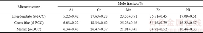
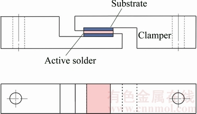
Fig. 2 Schematic diagram of configuration of shear test [24]
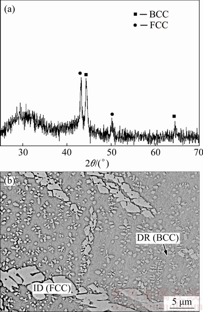
Fig. 3 XRD pattern (a) and microstructure (b) of HEA
The XRD diffraction peaks indicated the typical dendritic structure of dendritic (BCC) and interdendritic phases (FCC). This structure is illustrated in Fig. 3(b), which presents an SEM image of as-cast HEA sample and the typical dendritic structure of dendrites (DR) and interdendrites (ID). According to the EDS analyses listed in Table 1, the light interdendrite phases were Ni-rich FCC phase (��-FCC), the dark dendrite phases were Cr-rich BCC matrix phase (��-BCC), and a small fraction of cross-like Ni-rich FCC phases (��-FCC) were distributed within the majority dendritic structure. A similar result was also reported in Refs. [6,31].
3.2 Microstructure of joints
SEM cross-sectional images of HEA/HEA and HEA/Al soldered joints are shown in Figs. 4 and 5, respectively, and the EDS results taken from the testing positions denoted are summarized in Tables 2 and 3, respectively. Figure 4 presents SEM images of the HEA/HEA soldered joints. Figure 4(a) presents the microstructure of the HEA/HEA joint. To examine such joints clearly, it was necessary to capture high-resolution images of the HEA/active filler and active filler/HEA interfaces, as shown in Figs. 4(b) and (c), respectively. Because HEA contains large amounts of strong oxide-forming elements such as aluminum (Al) and chromium (Cr), a protective oxide layer formed on the film surface. Consequently, the HEA exhibited poor wetting characteristics. It can be clearly seen that the joined interfaces were completely bonded, without cracks or delaminations. The active soldering zone included a ��-Sn matrix (A1), black (Ti, Al)3Sn (A2), gray Ti6Sn5 (A3), light gray Sn-Ag-Ti (A4), white Ag3Sn (A5), and coarse Ti2Sn3 phase (A6). According to energy dispersive spectroscopy (EDS) analysis, as shown in Table 2, the chemical composition (mass fraction) of the black phase (A2) was Sn ((47.53��0.59)%), Ag ((0.55��0.30)%), Ti ((45.47�� 0.74)%), Al ((4.78��0.45)%), Cr ((0.60��0.34)%), and Fe ((1.07��0.30)%). A small amount of Al diffused from the HEA sample into the active filler area. This diffusion suggests that the Sn solder diffused toward the dissolved grain boundaries of the HEA substrate (Point a); the HEA grains migrated away from the base HEA substrate (Point b); and some HEA particles migrated into the solder filler area (Point c).

Fig. 4 Microstructures of HEA/HEA interface after active soldering
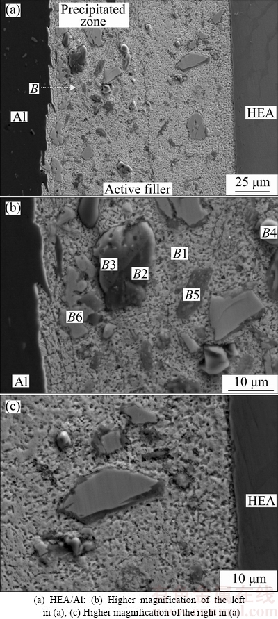
Fig. 5 Microstructures of HEA/Al interface after active soldering
However, the amounts of other alloying elements were very low (e.g., Cr and Fe) or nonexistent (e.g., Mn and Ni), suggesting that the HEA sample had a much lower diffusion rate. TSAI et al [32] reported that the sluggish diffusion kinetics is an important contributor to the outstanding properties of CoCrFeMn0.5Ni alloys. The larger lattice potential energy (LPE) fluctuation in the HEA sample leads to higher normalized activation energies and lower diffusion rate, which together cause the sluggish diffusion effect. This factor thus also reduces the diffusion of all alloying elements of the HEA alloy in the joint area during the direct active soldering process.
Table 2 EDS results taken from different positions as denoted in Fig. 4
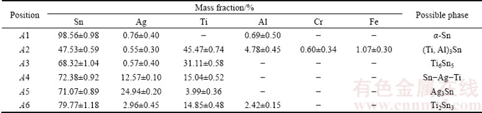
Table 3 EDS results taken from different positions as denoted in Fig. 5
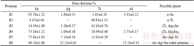
Figure 5 presents SEM images of the HEA/Al soldered joints. The active soldering zone included a ��-Sn matrix (B1), black ��-Ti (B2), (Ti, Ag)3Sn (B3), (Ti, Al)2Sn3 (B4), Sn-Ag-Ti (B5), and coarse Al-Ag-Sn phase (B6) [29]. The amount of Al in the active filler area was clearly higher in the HEA/Al sample than that in the HEA/HEA sample. Previous researchers have reported [6,27,31-33] that the formation of large Al-Ag-Sn particles depends on three factors: the dissolution of the Al plate, the varying solubility of Al in Sn at different temperatures (0.6%, mass fraction) at eutectoid 228 ��C and 0.15% (mass fraction) at room temperature) [34], and the ability of Ag (0.144 nm) and Al (0.143 nm) to form a substitutional solid solution, which leads to an appreciable replacement phenomenon. The same phenomenon has been observed previously [6]. It can also be seen in Fig. 5 that small particles of Al-rich phase precipitated in the Al/active solder interfacial area. Therefore, the solid Al substrates dissolved in the melted active solder and formed a coarse Al-Ag-Sn solid solution around the active filler/Al interface [35].
Fig. 6 Line scanning maps at HEA/active solder interface in Fig. 4(a) (Point A)
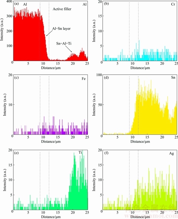
Fig. 7 Line scanning maps at Al/active solder interface in Fig. 5(a) (Point B)
Figures 6 and 7 respectively present the elemental profiles across the interfaces of HEA/HEA and HEA/Al soldered joints. Figure 6 shows the composition profile across an HEA/active filler interface following the path depicted in Fig. 4(a) (Point A). The profile shows a significantly narrow mixed zone (about 2 ��m) at the active filler/HEA interface. In addition, the amount of the base alloying element of the HEA was found to be trace or none. The diffusion of the HEA and active filler into each other was very low. A slightly increased concentration of Ti was also found at the joint interface as Ti-Sn phase. Previous studies [6,19,21-24] reported that Ti contributed significantly to joint formation on ceramics such as Al2O3, ITO, and TiO2. The results are in good agreement with those previously reported in the literature.
Figure 7 shows a composition profile across an Al/active filler interface following the path depicted in Fig. 5(a) (Point B). As shown in that figure, Sn and Al had a strong mutual affinity and coexisted in the interfacial reaction layer, corresponding to the Al-Sn phase. The thickness of the interfacial Al-Sn layer was about 6 ��m. In the active filler zone, Sn-Al-Ti phase formed.
3.3 Shear strength and fracture surface
Figure 8 shows the average shear strengths of the soldered joints. The joint strength of the HEA/HEA sample was (14.20��1.63) MPa, slightly lower than that (15.70��1.35) MPa of the HEA/Al joints. The interfacial microstructure of HEA/Al joints was free of defects (Fig. 4), so these joints demonstrated relatively high shear strength. Figure 9 presents SEM images taken from the fracture surfaces of the soldered joints. The typical fracture of the HEA/HEA joint soldered with SAT active filler at 250 ��C in air is shown in Figs. 9(a) and (b). The fracture surfaces exhibited mostly the characteristics of brittle rupture (marked with a��) and some cracks (marked with b��) in the soldering seam. It is likely that the crack initiated and propagated in the brittle Ti-Sn phase (marked with c��) in an early stage of the shear test, indicating that brittle fracture occurred in the HEA/HEA soldered joint. Figures 9(c) and (d) show the fracture morphologies of the HEA/Al soldered joint on Al side. The fractography was composed of brittle rupture steps and some plastic slip planes (marked with d��), demonstrating that the fracture mode of the soldered samples was semi- brittle fracture.
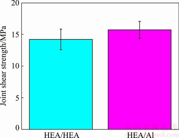
Fig. 8 Shear strengths of HEA/HEA and HEA/Al joints
4 Conclusions
In summary, through direct active soldering, HEA was successfully soldered with Al with SAT active filler and without flux at 250 ��C in air. During the direct active soldering, the diffusion of all alloying elements of the HEA sample was sluggish in the joint area. The joint strengths of the HEA/HEA and HEA/Al samples, as analyzed by shear testing, were (14.20��1.63) and (15.70��1.35) MPa, respectively. The fractography of the HEA/HEA soldered joint exhibited obvious brittle fracture characteristics, and the main fracture paths propagated mostly through the brittle Ti-Sn phase. However, in the HEA/Al joints, the fracture morphology was composed of brittle rupture steps and plastic slip planes, demonstrating that the fracture mode of the soldered samples was semi-brittle fracture.
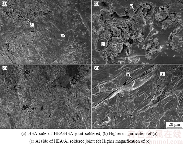
Fig. 9 Fractographs of joints bonded with active filler after shear strength testing
Acknowledgments
The authors acknowledge the financial support of this work from the Ministry of Science and Technology, Taibei, China, under Projects No. MOST 105-ET-E-020- 002-ET, 105-2622-E-020-003-CC3. SEM was performed by the Precision Instrument Center of National Pingtung University of Science and Technology, Taibei, China.
References
[1] CHIKUMBA S, RAO V V. High entropy alloys: Development and applications [C]//Proceedings of the 7th International Conference on Latest Trends in Engineering & Technology (ICLTET'2015). Irene, Pretoria, 2015: 26-27.
[2] DAVIS J R. Metals handbook [M]. OH: ASM International, 1990: 634.
[3] YEH J W, CHEN S K, LIN S J, GAN J Y, CHIN T S, SHUN T T, TSAU C H, CHANG S Y. Nanostructured high-entropy alloys with multiple principal elements: Novel alloy design concepts and outcomes [J].Advanced Engineering Materials, 2004, 6:299-303.
[4] TSAI M H, YEH J W. High-entropy alloys: A critical review [J]. Materials Research Letters, 2014, 2: 107-123.
[5] YE Y F, WANG Q, LU J, LIU C T, YANG Y. High-entropy alloy: Challenges and prospects [J]. Materials Today, 2016, 19: 349-362.
[6] TSAO L C, CHEN C S, CHU C P. Age hardening reaction of the Al0.3CrFe1.5MnNi0.5 high entropy alloy [J]. Materials Design, 2012, 36: 854-858.
[7] YE Y F, WANG Q, LU J, LIU C T, YANG Y. Design of high entropy alloys: A single-parameter thermodynamic rule [J]. Scripta Materalia, 2015, 104: 53-55.
[8] REN Ming-xing, LI Bang-sheng, FU Heng-zhi. Formation condition of solid solution type high-entropy alloy [J]. Transactions of Nonferrous Metals Society of China, 2013, 23: 991-995.
[9] LI Bao-yu, PENG Kun, HU Ai-ping, ZHOU Ling-ping, ZHU Jia-jun, LI De-yi. Structure and properties of FeCoNiCrCu0.5Alx high- entropy alloy [J]. Transactions of Nonferrous Metals Society of China, 2013, 23: 735-741.
[10] HEMPHILL M A, YUAN T, WANG G Y, YEH J W, TSAI C W, CHUANG A, LIAW P K. Fatigue behavior of Al0.5CoCrCuFeNi high entropy alloys [J]. Acta Materialia, 2012, 60: 5723-5734.
[11] XIA S Q,YANG X,YANG T F,LIU S,ZHANG Y. Irradiation resistance in AlxCoCrFeNi high entropy alloys [J]. Journal of the Minerals, Metals & Materials Society, 2015, 67: 2340-2344.
[12] HSU C Y, YEH J W, CHEN S K, SHUN T T. Wear resistance and high-temperature compression strength of FCC CuCoNiCrAl0.5Fe alloy with boron addition [J]. Metallurgical and Materials Transactions A, 2004, 35: 1465-1469.
[13] TONG C J, CHEN Y L, CHEN S K, YEH J W, SHUN T T, TSAU C H, CHANG S Y, Microstructure characterization of AlxCoCrCuFeNi high-entropy alloy system with multiprincipal elements [J]. Metallurgical and Materials Transactions A, 2005, 36: 881-893.
[14] CHEN Y Y, DUVAL T, HONG U T, YEH J W, SHIH H C, WANG L H, OUNG J C, Corrosion properties of a novel bulk Cu0.5NiAlCoCrFeSi glassy alloy in 288 ��C high-purity water [J]. Materials Letters, 2007, 61: 2692-2696.
[15] SINGH S, WANDERKA N, MURTY B S, GLATZEL U, BANHART J. Decomposition in multi-component AlCoCrCuFeNi high-entropy alloy [J]. Acta Materialia, 2011, 59: 182-190.
[16] TSAI M H, YEH J W, GAN J Y. Diffusion barrier properties of AlMoNbSiTaTiVZr high-entropy alloy layer between copper and silicon [J]. Thin Solid Films, 2008, 516: 5527-5530.
[17] TSAI M H, WANG C W, TSAI C W, SHEN W J, YEH J W, GAN J Y, WU W W. Thermal stability and performance of NbSiTaTiZr high-entropy alloy barrier for copper metallization [J]. Journal of the Electrochemical Society, 2011, 158: H1161-H1165.
[18] CHEN S H, KAO Y F. Near-constant resistivity in 4.2-360 K in a B2 Al2.08CoCrFeNi [J]. AIPAdvances, 2012, 2: 012111.
[19] CHANG S Y, TSAO L C, CHIANG M J, TUNG C N, PAN G H, CHUANG T H. Active soldering of indium tin oxide (ITO) with Cu in air using an Sn3.5Ag4Ti (Ce, Ga) filler [J]. Journal of Materials Engineering and Performance,2003, 12: 383-389.
[20] CHANG S Y, CHUANG T H, YANG C L. Low temperature bonding of alumina/alumina and alumina/copper in air using an Sn3.5Ag4Ti (Ce, Ga) filler [J]. JournalofElectronicMaterials, 2007, 36: 1193-1198.
[21]  M, ULRICH K. Shear strength and wettability of active Sn3.5Ag4Ti (Ce, Ga) solder on Al2O3 ceramics [J]. Materials & Design, 2011, 32: 3997-4003.
[22] CHANG S Y, CHUANG T H, TSAO L C, YANG C L, YANG Z S. Active soldering of ZnS-SiO2 sputtering targets to copper backing plates using an Sn3.5Ag4Ti (Ce, Ga) filler metal [J]. Journal of MaterialsProcessing Technology, 2008, 202: 22-26.
[23] TSAO L C. Direct active soldering of micro-arc oxidized Ti/Ti joints in air using Sn3.5Ag0.5Cu4Ti (RE) filler [J]. Materials Science and Engineering A, 2013, 565: 63-71.
[24] TSAO L C. Microstructural characterization and mechanical properties of microplasma oxidized TiO2/Ti joints soldered using Sn3.5Ag4Ti (Ce) active filler [J]. Journal of MaterialsScience: Materials inElectronics, 2014, 25: 233-243.
[25] QU Wen-qing, ZHOU Shuang-shuang, ZHUANG Hong-shou. Effect of Ti content and Y additions on oxidation behavior of SnAgTi solder and its application on dissimilar metals soldering [J]. Materials & Design, 2015, 88: 737-742.
[26] TSAO L C, CHANG S Y, HUANG M S, CHEN C S. Direct robust active bonding between Al heat sink and Si substrate [C]//Proceedngs of the 2012 International Conference on Electronic Packaging Technology & High Density Packaging. New York: IEEE, 2012.
[27] TSAO L C, HSIEH M J, CHEN T Y, CHENG S Y, CHEN C W. Active soldering of aluminum�Cgraphite composite to aluminum using Sn3.5Ag4Ti0.5Cu active filler [J]. International Journal of Materials Research, 2016, 107: 860-866.
[28] CHENG L X, LI G Y, WANG X Q, LI Z L, WU Z Z. Influence of active element ti on interfacial reaction and soldering strength between Sn3.5Ag4Ti (Ce,Ga) alloy filler and Si substrate [J]. MaterialsScienceandEngineering A, 2016, 658: 42-49.
[29] TSAO L C. Interfacial structure and fracture behavior of 6061 Al and MAO-6061 Al direct active soldered with Sn-Ag-Ti active solder [J]. Materials & Design, 2014, 56: 318-324.
[30] GUO S, HU Q, CHUN N G, LIU C T. More than entropy in high-entropy alloys: Forming solid solutions or amorphous phase [J]. Intermetallics, 2013, 41: 96-103.
[31] LEE C P, CHANG C C, CHEN Y Y, YEH J W, SHIH H C. Effect of the aluminium content of AlxCrFe1.5MnNi0.5 high-entropy alloys on the corrosion behaviour in aqueous environments [J]. Corrosion Science, 2008, 50: 2053-2060.
[32] TSAI K Y, TSAI M H, YEH J W. Sluggish diffusion in Co-Cr-Fe-Mn-Ni high-entropy alloys [J]. Acta Materialia, 2013, 61: 4887-4897.
[33] MCALISTER A J, KAHAN D J. The Al-Sn (aluminum-tin) system [J]. Bull Alloy Phase Diagrams, 1983, 4: 410-414.
[34] PERRONE A, ZOCCO A, de ROSA H, ZIMMERMANN R, BERSANI M. Al-Sn thin films deposited by pulsed laser ablation [J]. Materials Science and Engineering C, 2002, 22: 465-468.
[35] KATTNER U. Silver-aluminium-tin ternary alloys [M]. Weinheim: VCH, 1990: 74-79.
����Sn-Ag-Ti���Ժ���ֱ�ӻ�����Ӻ�Al0.3CrFe1.5MnNi0.5���غϽ���6061���Ͻ�
L. C. TSAO1, S. Y. CHANG2, Y. C. YU1
1. Department of Materials Engineering, National Pingtung University of Science & Technology, Neipu, Pingtung 91201, China;
2. Department of Mechanical Engineering, National Yunlin University of Science & Technology, Touliu, Yunlin 64002, China
ժ Ҫ�����غϽ�Al0.3CrFe1.5MnNi0.5(HEA)���������������ܡ��ڴ����������Ӻ��¶�Ϊ250 ��C����60 s�������£���Sn3.5Ag4TiΪ���Ժ��϶�HEA/HEA��HEA/6061-Al����ֱ�ӻ��������Ӻϣ��������������֯������ǿ�ȷ�����ʵ������ʾ���ڽӺϹ����У����غϽ�������Ԫ�ػ�����ɢ������������HEA/HEA��HEA/ 6061-Al��Ʒ�ļ���ǿ�ȷֱ�Ϊ (14.20��1.63) �� (15.70��1.35) MPa��HEA/6061-Al��Ʒ�Ķ�����������Եİ���Զ���������
�ؼ��ʣ����غϽ�Sn3.5Ag4Ti�������ϣ�Al0.3CrFe1.5MnNi0.5��ֱ�ӻ����
(Edited by Wei-ping CHEN)
Corresponding author: L. C. TSAO; Tel: +886-8-7703202 ext. 7560; Fax: +886-8-7740552; E-mail: tlclung@mail.npust.edu.tw
DOI: 10.1016/S1003-6326(18)64707-7

