Effect of wire mesh interlayer in explosive cladding of dissimilar grade aluminum plates
来源期刊:中南大学学报(英文版)2019年第3期
论文作者:SARAVANAN S RAGHUKANDAN K PRABHAT Kumar
文章页码:604 - 611
Key words:explosive cladding; aluminum; wire mesh; microstructure; strength
Abstract: Explosive cladding of Al 5052–Al 1100 plate, interfaced with a stainless steel wire mesh interlayer, is attempted. Loading ratio and standoff distance were varied. An increase in loading ratio (R) and standoff distance (S) enhances the plate velocity (Vp), dynamic bend angle (β) and pressure developed (P). The interface morphology of the explosive clads confirms strong metallurgical bond between the wire mesh and aluminum plates. Further, a smooth transition from straight to undulating interlayered topography is witnessed. The introduction of a wire mesh, as interlayer, leads to an improvement in mechanical strength with a slender reduction in overall corrosion resistance of the “explosive clads”.
Cite this article as: SARAVANAN S, RAGHUKANDAN K, PRABHAT Kumar. Effect of wire mesh interlayer in explosive cladding of dissimilar grade aluminum plates [J]. Journal of Central South University, 2019, 26(3): 604–611. DOI: https://doi.org/10.1007/s11771-019-4031-9.

J. Cent. South Univ. (2019) 26: 604-611
DOI: https://doi.org/10.1007/s11771-019-4031-9

SARAVANAN S1, RAGHUKANDAN K2, PRABHAT Kumar3
1. Department of Mechanical Engineering, Annamalai University, Annamalainagar,Tamilnadu 608002, India;
2. Department of Manufacturing Engineering, Annamalai University, Annamalainagar,Tamilnadu 608002, India;
3. Department of Mechanical Engineering, Indur Institute of Engineering & Technology,Telangana 502277, India
 Central South University Press and Springer-Verlag GmbH Germany, part of Springer Nature 2019
Abstract: Explosive cladding of Al 5052–Al 1100 plate, interfaced with a stainless steel wire mesh interlayer, is attempted. Loading ratio and standoff distance were varied. An increase in loading ratio (R) and standoff distance (S) enhances the plate velocity (Vp), dynamic bend angle (β) and pressure developed (P). The interface morphology of the explosive clads confirms strong metallurgical bond between the wire mesh and aluminum plates. Further, a smooth transition from straight to undulating interlayered topography is witnessed. The introduction of a wire mesh, as interlayer, leads to an improvement in mechanical strength with a slender reduction in overall corrosion resistance of the “explosive clads”.
Key words: explosive cladding; aluminum; wire mesh; microstructure; strength
Cite this article as: SARAVANAN S, RAGHUKANDAN K, PRABHAT Kumar. Effect of wire mesh interlayer in explosive cladding of dissimilar grade aluminum plates [J]. Journal of Central South University, 2019, 26(3): 604–611. DOI: https://doi.org/10.1007/s11771-019-4031-9.
1 Introduction
Aluminum 1100 is employed in aerospace, automobile and structural applications due to its light weightedness, better rigidity and lower fracture toughness. This alloy’s corrosion and wear resistance, thermal conductivity, anti-friction and mechanical properties are improved by cladding with other alloys [1]. Aluminum 5052 is a potential candidate for cladding, used widely in various demanding applications viz., aircraft, marine and transportation industry parts, home appliances and equipment for bulk processing of food [2]. The mechanical strength of the aluminum 5052-aluminum 1100 dissimilar clad is further enhanced by introducing a stainless steel wire mesh between them. Though the production of “wire mesh reinforced” dissimilar aluminum plates is possible by diffusion bonding and gas pressure infiltration, the presence of high heat and a longer processing time promote the formation of brittle intermetallic compounds at the interface [3]. Alternatively, explosive cladding offers a reliable alternative to attain wire mesh reinforced aluminum clads with a shorter processing time (<50 μs) and a minimal increase in temperature [4].
Explosive cladding of aluminium with other metals viz., copper [5], dual phase steel [6], magnesium [7] and aluminium [8] was reported by earlier researchers. HAN et al [9] cladded Al-steel plates with varied thickness (0.2 mm to 1 mm) interlayer and concluded that the shear strength is inversely proportional to interlayer thickness, whereas, SARAVANAN et al [10] attempted different metallic interlayer’s between Al–Cu plates and concluded that higher density interlayer improves the mechanical strength of clads. In an earlier study, BHALLA et al [3] successfully employed steel wires between aluminum plates. Recently, GULENC et al [11] cladded aluminum plates by positioning wire mesh at different orientations on the base plate and recommended an angle of 45° orientation for better strength. However, the studies related to usage of wire mesh as interlayer between dissimilar aluminium plates is scarce, and is attempted herein. The microstructural, mechanical and corrosion properties of the wire mesh interlayered dissimilar aluminum explosive clad are determined as per the relevant standards and the results are presented.
2 Experimental procedure
A parallel explosive cladding configuration (Figure 1), with and without interlayer, was attempted. A 0.4 mm thick stainless steel wire mesh having 45° orientation was positioned as interlayer between flyer (Al 5052) and base plates (Al 1100) of similar dimensions (80 mm×60 mm). The thicknesses of flyer and base plates were 2 mm and 6 mm, respectively. The chemical composition and mechanical properties of the participant metals are given in Tables 1 and 2, respectively. Commercially available chemical explosive (detonation velocity-4000 m/s, density-1.2 g/cm3) was packed above the flyer plate at different loading ratios (R=0.7 to 0.9), and the detonator was positioned on one corner of the explosive pack. Equi-standoff distance between flyer-interlayer and interlayer- base plates was varied from 5 mm to 8 mm. The experimental conditions were fixed based on the trial experiments.
Figure 1 Explosive cladding with interlayer
Table 1 Chemical composition (mass fraction, %) of participant metals
Table 2 Mechanical properties of participant metals
Post cladding, the specimens for metallographic observations were sectioned parallel to the detonation direction, following standard metallurgical procedures viz., grinding, polishing and etching (Kellers reagent-5 mL HF, 10 mL H2SO4, 85 mL H2O for 20 s). The post cladding metallographic analysis were conducted in a VERSAMAT–3 with Clemex image analyzing system and scanning electron microscope (SEM) (JEOL, JSM–6610LV) equipped with energy dispersive spectrometer (EDS). Vickers micro- hardness measurement across the explosive clads was conducted on a ZWICK micro-hardness tester applying 100 g load (ASTM E 384 standard) and the results are presented. Ram tensile test specimens (Figure 2) were prepared, such that the tensile load is applied on the wire mesh-aluminum interface until failure, by compressing the ram into the space drilled out in the base plate, in a UNITEK-94100 universal testing machine. For each experimental condition, two samples were tested and the average values are reported.
The shear test sample was prepared as per ASTM B 898 standard (Figure 3) with a compressive force applied on the interlayered explosive clad.Fractography analysis on the tensile specimens was performed in a SEM (JEOL, JSM–6610LV). The cavitation erosion-corrosion samples of 15 mm×15 mm, in the form of coupons, were sliced along the interface containing flyer; interlayer and base plate are placed in a glass of 3.5% NaCl-water solution for 240, 720 and 1440 h, and the variation in weight was observed in an electronic scale having accuracy of 0.0001 g.
Figure 2 Ram tensile test (Unit: mm)
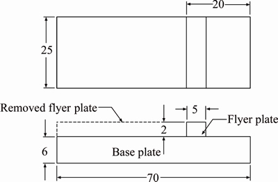
Figure 3 ASTM side shear test (Unit: mm)
3 Results and discussion
3.1 Mechanism of cladding
The detonation of a chemical explosive is a controlled progressive ignition, propagating from one end of the flyer plate, with a precise detonation rate. The gas expansion, following detonation, from the chemical explosion creates huge pressure at the collision point and accelerates the flyer plate at a definite velocity, Vp, across the standoff distance to result in an angular collision with the wire mesh interlayer. The velocity of flyer plate (Vp) is determined by [8]
 (1)
(1)
where Vd is the detonation velocity of the explosive and β is the dynamic bend angle determined by [12]
 (2)
(2)
where R, S and te denote loading ratio, standoff distance and thickness of the explosive, respectively. K is a constant varing from 1.96 to 2.6 depending on the nature and thickness of explosive.
On collision, the dissipation of available kinetic energy and the development of high pressure (P) at the interface, create plasticity at the bottom and top sections of the flyer plate and wire mesh interlayer respectively. SATYANARAYAN et al [13] opined that the kinetic energy dissipation at the interface promotes plasticity. Consequently, a thin layer of the flyer plate and interlayer, molten surface contaminants, oxides and impurities are ejected as surface jetting, while the inner section of the softer aluminum flyer plate flows through the sluices in the wire mesh (interlayer), to create a metallurgical bond. However, the pressure developed at the interface is given by [14]
 (3)
(3)
where ρ is the density of flyer plate. After first collision, the flyer-interlayer clad moves with a reduced flyer plate velocity, Vp1 and pressure to impinge with the base plate to craft the second interface. Further, the pot holed surface of the wire mesh interlayer enhances the friction between mating surfaces and is more advantageous than a conventional sheet interlayer.
3.2 Metallographic studies
The influence of process parameters viz., loading ratio, R, and standoff distance, S on the interface microstructure of dissimilar aluminum explosive clad with and without wire mesh interlayer is shown in Figure 4. The presence of wire mesh is observed in the form of bright circular spots and a thin white streak in longitudinal and transverse sections respectively. The microstructure transforms from a straight to wavy interfacial morphology, with an increase in loading ratio, R and standoff distance, S. Formation of molten layer is witnessed in conventional explosive clad (Figure 4(a)), whereas, interlayered clads (Figures 4(b)–(e)) are free from defects viz., cracks and molten layer at lower loading ratio and standoff distance conditions.
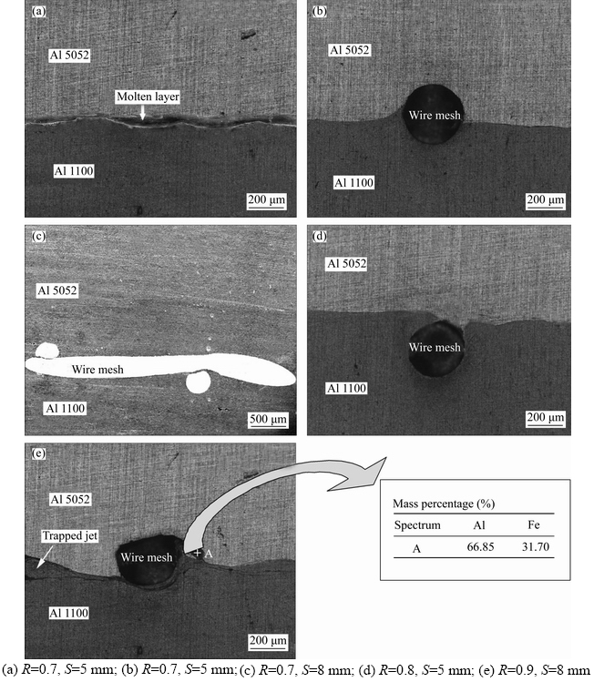
Figure 4 Microstructure of Al–Al explosive clad ((a, b, d, e) Optical; (c) SEM):
The characteristic undulating interface with a thin streak of molten layer (Figure 4(a)) is witnessed in the explosive clad interface without interlayer. This is due to the complete conversion of available kinetic energy into thermal energy and the minimum friction experienced. When an wire mesh is introduced as interlayer for a similar experimental condition (R=0.7, S=5 mm), the kinetic energy utilization and friction increase due to the enhancement in contact area (flyer-interlayer and interlayer-base) and the uneven surface of the wire mesh interlayer respectively. Consequently, the rapidity of flyer plate and the developed pressure reduce to result in a straight interface (Figure 4(b)). For an increase in standoff distance (8 mm) for a similar loading ratio (R=0.7), the flyer plate travels an additional distance at an angle β, to build more pressure (5437.8 bar) at the interface (Figure 4(c)) and leads to a higher interfacial amplitude (20 μm).
When the loading ratio, R increased to 0.8 for a standoff distance 5 mm, the flyer plate velocity (Vp=706.28 m/s), dynamic bend angle (β=10.12°) and the pressure (6734.2 bar) developed at the interface increases. Though the energy available and the pressure developed at the interface increase with loading ratio, R, a straight interface emerges owing to the lower standoff distance (Figure 4(d)). Conventionally, wavy interfaces are preferred, though straight interface also results in a better clad strength as reported by KAHRAMAN et al [15] and detailed in the next section(section 3.3) Further increase in loading ratio and standoff distance (R=0.9, S=8 mm) enhances the dynamic bend angle, β (10.89°), pressure developed (7789.4 bar) and flyer plate velocity (759.6 m/s) to increase the thickness of interfacial plastic region. This leads to creating interfacial waves having higher amplitude (45 μm) and wavelength (125 μm) as observed in Figure 4(e). However, the formation of molten layer, visible as black patches, closer to the vicinity of the interface is observed due to the additional pressure and kinetic energy spent at the interface as reported by TAMILCHELVAN et al [16] who cladded titanium-steel. In addition, the unescaped jet manifests into “trapped jet” in the vortex, formed before and after each undulation, obtained by the oscillation in the fluid like jet flow. The EDS analysis performed on the interface (marked as “A”) contains 66.85% of weaker metal aluminum and 31.7% of Fe. The phenomenon of intermetallic formation at higher loading ratio is consistent with the observations of MANIKANDAN et al [12]. Therefore, it may be inferred for a higher standoff distance and a loading ratio, R, of 0.7 and 0.8, the presence of wire mesh suppresses the formation of intermetallic compounds and enhances the weldability.
3.3 Mechanical strength
3. 3. 1 Micro-hardness
The average of three Vickers micro-hardness measurements, at equal intervals from the cross sections of interlayered explosive clad, for different loading ratios and a constant standoff distance (8 mm), is shown in Figure 5. The enhancement in hardness is not significant at regions away from interface (750 μm) following the reduction in plastic deformation, as reported by ASEMABADI et al [17]. Though there is no significant variation in the hardness of stainless steel wire mesh (HV 158), the post clad hardness of aluminum flyer and base plates are higher than pre clad conditions (Al 1100 HV 47, Al 5052 (HV 74)), as a consequence of high pressure and cold deformation experienced by them. The increment in hardness on both flyer and base plates is proportional to the loading ratio as the maximum hardness of HV 110 is observed on the flyer plate side, closer to the interface (≤ 50 μm) for a loading ratio of 0.9.
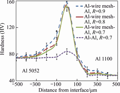
Figure 5 Micro-hardness variation across explosive clad
However, for loading ratio of 0.8% and 0.7%, 10% and 12% lower hardness are observed respectively at the regions closer to the interface due to the variation in pressure developed and kinetic energy utilization as reported by SARAVANAN et al [18]. The hardness of the “interlayer less” explosive clad displays a similar trend having a maximum hardness (HV 92) at the interface, but less than the ‘interlayered’ explosive clad for all attempted conditions, following the absence of wire mesh interlayer.
3.3.2 Ram tensile test
Tensile test samples prior and after the testing are shown in Figures 6(a) and (b) respectively. The failed specimen (Figure 6(b)) confirms that the absence of wire mesh pulls out or clads separation. The maximum tensile strength was obtained for a loading ratio of 0.9 and a higher standoff distance {8 mm–148 MPa}, whereas the minimum strength(132 MPa) is recorded at lower loading ratio and standoff distance (R=0.7, S=5 mm). The tensile strength increases with the loading ratio and standoff distance, due to the variations in the pressure developed, magnitude of cold deformation and the kinetic energy spent at the interface. PRAZMOWSKI and PAUL [19] opined that the increase in standoff distance enhances the mechanical strength and is consistent with this study.
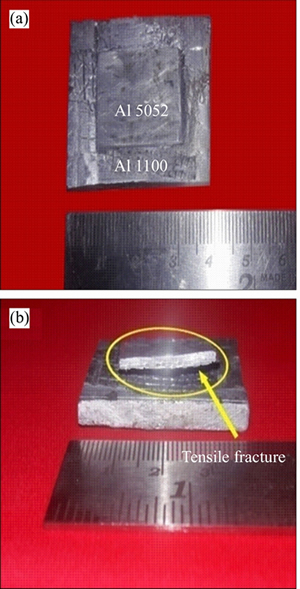
Figure 6 Ram tensile specimen (a) and after testing (b)
The minimum strength of the ‘interlayered’ clad is higher than “interlayer less” cladding (Figure 7) and the base metal Al 1100 (117 MPa). Further it is observed that the lowest tensile strength for the wire mesh’ interlayered’ Al–Al explosive clad for a loading ratio, R of 0.7 is 15 % higher than the “interlayer less” explosive clad for similar experimental conditions. The introduction of wire mesh interlayer, thus, improves the mechanical strength of the explosive clads and the results are in agreement with the reports of SARAVANAN et al [20].
The tensile fractograph of interlayered aluminum clad (Figure 8) features the blending of wires with the base metals. The impression created by the wires on the base plate is clearly visible. However, the presence of either cleavage or intergranular fracture that characterizes a brittle fracture are not observed.
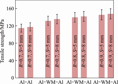
Figure 7 Tensile strength of Al–Al explosive clads
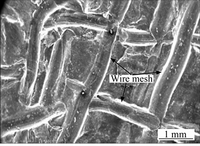
Figure 8 Tensile fractograph of aluminum clad
3.3.3 ASTM side shear test
Compressive force is applied on the dissimilar aluminum explosive clad by measuring load with respect to displacement until the sample failed on an Instron universal testing machine at 0.5 mm/min. The shear test samples prior and after the fracture are shown in Figures 9(a) and (b), respectively.
The side shear strength of the interlayered clads is higher than interlayer less clads and the weaker parent metal (Al 1100) for all attempted conditions (Figure 10) and is consistent with result by NING et al [21]. Further, the maximum shear strength (95 MPa) is obtained at higher loading ratios owing to the formation of undulating interfaces created due to higher pressure developed and the additional kinetic energy spent at the interface.
3.4 Corrosion test
The explosive clad specimens were recovered from the corrosive environment, cleaned as per EN ISO 7384 standards, weighed and the variation in weight per cm2 surface area was determined. The variation in weight after 240, 720 and 1440 h is not significant in conventional Al–Al explosive clads (original weight-4 g) as shown in Figure 11.
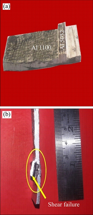
Figure 9 Shear test specimen (a) and fractured specimen (b)
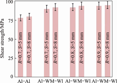
Figure 10 Shear strength of Al-Al explosive clad
Though the corrosion rate in ‘interlayer less’ explosive clad is negligible, the weight reduction in ‘interlayered’ explosive clad after 1440 h varies in 0.027–0.037 g/cm2. The exposure of stainless steel on the corrosive environment leads to the slender reduction in weight in‘interlayered’explosive clads. However, the maximum corrosion occurs at a loading ratio of 0.9 (weight reduction for Al–Al= 0.037 g/cm2) as reported by KAHRAMAN et al [15].
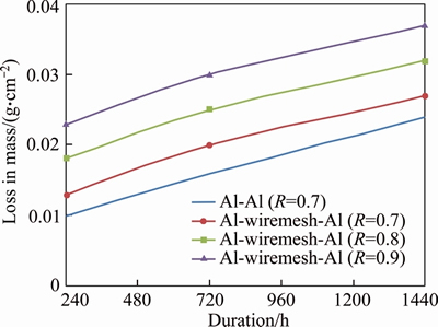
Figure 11 Effect of corrosion with respect to time
4 Conclusions
The salient conclusions of explosive cladding of dissimilar grade aluminum plates with a stainless steel wire mesh interlayer are as follows.
1) The molten aluminum flows through the sluices in the wire mesh to achieve metallurgical bonding with the base metal.
2) The uneven surface on the wire mesh enhances the friction force and results in a better clad than a sheet interlayer.
3) Increase in loading ratio and standoff distances enhances the thickness of plastic region and thereby dictates the nature of clads.
4) The maximum microhardness was observed in interface due to the presence of wire mesh and plastic deformation.
5) Tensile and shear strength of the interlayered explosive clad is higher than weaker parent metal owing to the presence of harder stainless steel and metallurgical bonding.
6) Corrosion studies reveal the minimum reduction in mass even at a PH level of 8.
References
[1] JI H, WANG J, LI M. Evolution of the bulk microstructure in 1100 aluminum builds fabricated by ultrasonic metal welding [J]. Journal of Materials Processing Technology, 2014, 214(2): 175–182.
[2] MANDAL N R. Aluminum welding [M]. Cambridge: Wood Head Publishing, 2002.
[3] BHALLA A K, WILLIAMS J D. Production of stainless steel wire-reinforced aluminium composite sheet by explosive compaction [J], Journal of Materials Science, 1977, 12(3): 522–530.
[4] SARAVANAN S, RAGHUKANDAN K. Diffusion kinetics in explosive cladding of dissimilar alloys as described through the Miedema model [J]. Archives of Metallurgy and Materials, 2014, 59(4): 1615–1618.
[5] ACARER M. Electrical, corrosion and mechanical properties of aluminium-copper joints produced by explosive welding [J]. Journal of Materials Engineering and Performance, 2012, 21(11): 2375–2379.
[6] ACARER M, DEMIR B. An investigation of mechanical and metallurgical properties of explosive welded aluminum-dual phase steel [J]. Materials Letters, 2008, 62(25): 4158–4160.
[7] ZHANG N, WANG W, CAO X, WU J. The effect of annealing on the interface microstructure and mechanical characteristics of AZ31B/AA6061 composite plates fabricated by explosive welding [J]. Materials and Design, 2015, 65: 1100–1109.
[8] GRIGNON F, BENSON D, VECCHIO K S, MAYERS M A. Explosive welding of aluminum to aluminum: Analysis, computations and experiments [J]. International Journal of Impact Engineering, 2004, 30(10): 1333–1351.
[9] HAN J H, AHN J P, SHIN M C. Effect of interlayer thickness on shear deformation behavior of AA5083 aluminum alloy/SS41 steel plates manufactured by explosive welding [J]. Journal of Materials Science, 2003, 38(1): 13–18.
[10] SARAVANAN S, RAGHUKANDAN K, HOKAMOTO K. Improved microstructure and mechanical properties of dissimilar explosive cladding by means of interlayer technique [J]. Archives of Civil and Mechanical Engineering, 2016, 16(4): 563–568.
[11] GULENC B, KAYA Y, DURGUTLU A, GULENC I T, YILDIRIM M S, KAHRAMAN N. Production of wire reinforced composite materials through explosive welding [J]. Archives of Civil and Mechanical Engineering, 2016, 16(1): 1–8.
[12] MANIKANDAN P, HOKAMOTO K, FUJITA M, RAGHUKANDAN K, TOMASHIGE R. Control of energetic conditions by employing interlayer of different thickness for explosive welding of titanium/ 304 stainless steel [J]. Journal of Materials Processing Technology, 2008, 195(1–3): 232–240.
[13] SATYANARAYA N, TANAKA S, MORI A, HOKAMOTO K. Welding of Sn and Cu plates using controlled underwater shock wave [J]. Journal of Materials Processing Technology, 2017, 245: 300–308.
[14] WANG B, XIE F, LUO X, ZHOU J. Experimental and physical model of the melting zone in the interface of the explosive cladding bar [J]. Journal of Materials Research and Technology, 2016, 5(4): 333–338.
[15] KAHRAMAN N, GULENC B, FINDIK F. Corrosion and mechanical-microstructural aspects of dissimilar joints of Ti–6Al–4V and Al plates [J]. International Journal of Impact Engineering, 2007, 34(8): 1423–1432.
[16] TAMILCHELVAN P, RAGHUKANDAN K, SARAVANAN S. Kinetic energy dissipation in Ti-SS explosive cladding with multi loading ratios [J]. Iranian Journal of Science and Technology, Transactions of Mechanical Engineering, 2014, 38(M1): 91–96.
[17] ASEMABADI M, SEDIGHI M, HONARPISHEH M. Investigation of cold rolling influence on the mechanical properties of explosive-welded Al/Cu bimetal [J]. Materials Science and Engineering A, 2012, 558: 144–149.
[18] SARAVANAN S, RAGHUKANDAN K, HOKAMOTO K. Effect of process parameters on microstructural and mechanical properties of Ti-SS 304L explosive cladding [J]. Journal of Central South University, 2017, 24(6): 1245–1251.
[19] PRAZMOWSKI M, PAUL H. The effect of stand-off distance on the structure and properties of zirconium – carbon steel bimetal produced by explosion welding [J]. Archives of Metallurgy and Materials, 2012, 57(4): 1201–1210.
[20] SARAVANAN S, RAGHUKANDAN K. Influence of interlayer in explosive cladding of dissimilar metals [J]. Materials and Manufacturing Processes, 2013, 28(5): 589–594.
[21] NING J, ZHANG L J, XIE M X, YANG H X, YIN X Q, ZHANG J X. Microstructure and property inhomogeneity investigations of bonded Zr/Ti/steel trimetallic sheet fabricated by explosive welding [J]. Journal of Alloys and Compounds, 2017, 698: 835–851.
(Edited by DENG Lü-xiang)
中文导读
爆炸包层中不锈钢丝网夹层对不同等级铝板的影响
摘要:尝试将不锈钢丝网夹层与Al 5052–Al 1100板的爆炸包层接合,并优化其加载比和间隔距离等参数。加载比(R)和间隔距离(S)的增加提高了板速度(Vp),动态弯曲角(β)和产生的压力(P)。爆炸包层的界面形态证实了金属丝网和铝板之间的强烈冶金结合。此外,实现了从直的到波状层间形貌的平滑过渡。将金属丝网作为夹层,提高了机械强度,但稍微降低了“爆炸包层”的整体耐腐蚀性。
关键词:爆炸包层;铝;钢丝网;微结构;强度
Received date: 2017-06-28; Accepted date: 2018-11-10
Corresponding author: SARAVANAN S, PhD, Assistant Professor; Tel: +91-9443676936; E-mail: ssvcdm@gmail.com; ORCID: 0000- 0003-2961-4420

