
Heat shock behavior of permanent die during
non-solid near-net forming process
ZHANG Mi-lan(张密兰)1,2, SHAN Zhong-de(单忠德)1, XING Shu-ming(邢书明)3,
JIANG Chao(姜 超)1, XU Ying(许 应)1
1. State Key Laboratory of Advanced Forming Technology and Equipment, Advanced Manufacture Technology Center, China Academy of Machinery Science and Technology, Beijing 100083, China;
2. School of Mechanical and Engineering, University of Science and Technology Beijing, Beijing 100083, China;
3. School of Mechanical, Electronic and Control Engineering, Beijing Jiaotong University, Beijing 100044, China
Received 10 August 2009; accepted 15 September 2009
Abstract: Heat shocks caused by alloy melt and coat spraying are the main reason of die plastic deformation and early fracture. Based on theoretical analysis of heat shock phenomenon, two characteristic parameters of die damage caused by heat shock were proposed, which are heat shock plastic deformation index (HSPI) and heat shock crack index (HSCI). The effect of heat shock on die plastic deformation and fracture behaviors was described quantitatively by these two parameters. HSPI represents approaching of heat shock stress to die yield stress. Plastic deformation will happen on a die if this index reaches 1. HSCI represents approaching of heat shock stress to die tensile strength. Die fracture will happen if this index reaches 1. According to theoretical analysis of heat transfer, theoretical models of HSPI and HSCI were established. It is found that, the smaller the interfacial thermal resistance (ITR) is, the higher the pouring temperature and die temperature are before heat shock, and the greater the HSPI and HSCI are, which can be fitted as exponential curves, linear and cubic curves.
Key words: non-solid near-net forming; die; heat shock; heat shock plastic deformation index; heat shock crack index
1 Introduction
Non-solid near-net forming technology (NNFT) is a class of forming technologies, which fills die cavity with alloy of good rheological property at non-solid-state and makes it solidify under gravity or additional pressure. Parts made by NNFT have good surface roughness, precise shape and dimension, and good mechanical properties, which can be used as components directly or need only few processing. During NNFT production, the die temperature increases and cools down rapidly for pouring and coat spraying. It was proved that, these heat shocks induce devastating impacts to die, which reduces die life greatly and is one of the key issues for NNFT popularization.
Till now, researches of heat shock mainly focused on ceramics, refractory materials, carbide alloys and welding. There were no clear and reasonable quantitativeparameters to evaluate heat shock damage (HSD) and material property of resisting heat shock damage (MPRHSD). For example, heat shock fatigue crack breeding time[1], crack growth rate or residual flexural strength[2] were too complicated, and maximum temperature difference that material could bear[3-5] didn’t consider practical processing factors and couldn’t be used to analyze and control HSD of a die. And relationships between process parameters and die failure, such as die plastic deformation and crack, were unclear too[6-8].
Evaluating HSD and MPRHSD correctly is basic problem of studying relationship between heat shock and die failure. Therefore, quantitative parameters of describing HSD and MPRHSD were studied firstly in this work, and then the relationships between processing parameters and HSD were studied, finally die failures caused by heat shock were discussed.
2 Evaluating parameters of HSD and MPRHSD
During heat shock process, temperature on die cavity changes dramatically, and great temperature difference appears. If this temperature difference is taken as evaluating parameter of heat shock, while easy to be understood, it does not reflect the heat shock stress, since there are great heat shock stress differences for different material properties and temperatures at the position where the same temperature differences appear.
In fact, the greater the temperature difference caused by heat shock, the greater the stress near cavity for given die material and the possibility of die failure. So, heat shock stress is more meaningful to express heat shock than the temperature difference.
If the die temperature difference is greater, but the temperature at this position is much lower, then die failure may not happen. Therefore, not only temperature difference and heat shock stress are meaningful to die failure, but also the temperature before and during heat shock and material properties should be considered. Heat shock stress σT is
σT=[Eα/(1-ν)] ?ΔT (1)
where ΔT , named as heat shock temperature difference (HSTD for short), is the difference of the highest temperature during heat shock process and the die temperature Tp before heat shock process; α is the thermal expansion coefficient during range of HSTD; considering temperature variation influence on die properties, E and v are elastic modulus and Poisson ratio at mid temperature (Tp+ΔT/2) during heat shock process.
If σT is greater than die yield stress σs at the highest temperature Tp+ΔT, local plastic deformation will occur; if σT is greater than die tensile strength σb at temperature Tp+ΔT, crack will occur. That is to say, the ratios of heat shock stress to die yield strength and to tensile strength, named as heat shock plastic deformation index Ωs and heat shock crack index Ωb, can be used as evaluating parameters of HSD. The two dimensionless parameters are
Ωs=σT/σs (2)
Ωb=σT/σb (3)
Substitute Eq.(1) into the upper two equations, then
Ωs=[Eα/σs(1-ν)] ?ΔT (4)
Ωb=[Eα/σb(1-ν)] ?ΔT (5)
If Ωs<1, Ωs expresses the extent that heat shock stress is close to die yield strength quantitatively. The greater the Ωs, the greater the trend that plastic deformation happens. If Ωs=1, heat shock stress reaches the die yield strength, then the die is at the critical state of plastic deformation occurring. If Ωs>1 and Ωb<1, plastic deformation occurs but crack does not happen. The greater the Ωb, the greater the trend that crack occurs. If Ωs>1 and Ωb≥1, that is, heat shock stress is greater than die tensile strength, then crack would happen rapidly to release heat shock stress.
Above analyses show that the trend of Ωs and Ωb closing to 1 means the trend of plastic deformation and crack occurring, and Ωs and Ωb could be used to evaluate the trend of plastic deformation and crack occurring caused by heat shock stress. On the other hand, supposing
Γs=σs(1-ν)/Eα (6)
Γb=σb(1-ν)/Eα (7)
Then Eq.(2) and Eq.(3) could be written as
Ωs=ΔT/Γs (8)
Ωb=ΔT/Γb (9)
where Γs and Γb named as material resisting plastic deformation factor and resisting crack factor, are parameters related to material properties.
It is known from Eq.(8) and Eq.(9) that, the greater the Γs and Γb are, the smaller the Ωs and Ωb are with the same temperature difference and the better the resisting die failure is. That is to say, Γs and Γb can be used as characteristic parameters of MPRHSD.
3 Calculating models of HSD factors
There are two kinds of heat shock during non-solid near-net forming process. One happens during pouring and filling, and the other happens during coat spraying.
3.1 Models of HSD factors during pouring and filling
During short period of heat shock, drastic temperature rising happens on die cavity; temperature on the outside die surface is almost constant; and the heat transfer near die/part interface can be seen as one-dimensional. Then, the heat transfer during heat shock is simplified as one-dimensional non-steady semi-infinite object. Assume that the alloy melt temperature Tq is the pouring temperature, which does not change during heat shock process. For alloy shrinkage and coat spraying, an interfacial thermal resistance exists between die and part, and this interfacial thermal resistance can be supposed to be constant. The heat conductivity model is shown in Fig.1.
Equivalent die thickness is introduced to solve heat transfer problem with interfacial temperature difference. This method transfers interface to the increase of die thickness from heat transfer view that interface thermal resistance equals thermal resistance of equivalent die thickness Ri, which means that temperature difference caused by interface equal that caused by equivalent die thickness. Then, the complicate three-body heat transfer is simplified as ideal two-body heat transfer, as shown in Fig.2.

Fig.1 Simplified thermal conductivity model

Fig.2 Equivalent die thickness
Without considering the heat absorbed by equivalent die thicknesses de, there is
Ri=de/λ1 (10)
where λ1 is the die thermal conductivity.
de=Ri?λ1 (11)
Then the die temperature field is[9]
 (12)
(12)
where a1=λ1/(ρ1?с1) is the die thermal diffusivity at temperature Tp+ΔT/2; ρ1 and с1 are the density and specific heat;  is the Gauss error function; and τ is the heat shock duration.
Substituting Eq.(11) and Eq.(12) into Eq.(4) and Eq.(5), respectively, the calculating models are obtained
 (13)
(13)
 (14)
(14)
3.2 Models of HSD factors during coat spraying
In the pouring and filling process, drastic temperature descending happens only on die cavity during coat spraying. The temperature on the outside die surface is almost constant, and the heat absorbed by coat spraying, qco, is constant under the given spraying speed, then this heat conductivity can be seen as one-directional with the given initial temperature and constant heat flux. Adopting the average die temperature Tp′ after former forming process to be the initial temperature, the die temperature field during coat spraying process is[10]
 (15)
(15)
where  is the integral of co-error function.
Substitute Eq.(15) into Eq.(4) and Eq.(5), then,
 (16)
(16)
 (17)
(17)
4 Influences of HSD factors
Cylinders were representative parts made by NNFT, and a cylinder of d80 mm×100 mm was adopted as simulating model. The simulating system is shown in Fig.3. H13 steel and 45 steel were adopted as die and part materials.
The forming process was: die preheating →coat
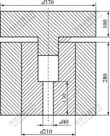
Fig.3 Scheme of simulating system
spraying→ pouring→ die closing→ pressure holding→ upper die resetting→ knocking out→ lower cylinder resetting →coat spraying (next process). In order to simplify calculating cost, pouring, die closing, knocking out and resetting were seen as to be done instantly, then the forming process became: pouring→ pressure holding→ coat spraying.
ANSYS software was adopted here for its functions could satisfy the simulation requirements[11-12]. During simulation, the effect of alloy flow was dealt with enlarging thermal conductivity of alloy 1.5 times that of customary; and super-cooling of alloy was ignored. Zero-thickness interfacial elements were chosen to deal with interfacial thermal resistance[13]. Enthalpy method was chosen to deal with nonlinear transient heat transfer. Initial temperatures of die and part were T(x, y, τ)=Tp and T(x, y, 0)=Tq, air temperature was 25 ℃, and convection coefficient of die/air was 65 W/(m2?℃).
The model was axisymmetric, so half plane was chosen. PLANE55 elements of 0.004 mm side-length were adopted on die and part. Aim elements and contact elements were generated on interface, as shown in Fig.4.

Fig.4 Simulation model
4.1 Influence of ITR on HSD factors
Ideal contact (supposing ITR be 2×10⁻⁶ m2?℃/W), and ITR values of 2×10⁻⁵, 3.33×10⁻⁵, 1×10⁻⁴ and 2×10⁻⁴ m2?℃/W were chosen; the pouring temperature was 1 520 ℃, and the die temperature before heat shock was 200 ℃. Substitute the simulation results into Eq.(4) and Eq.(5) to obtain HSPI and HSCI. Table 1 lists the simulation and calculating results.
Table 1 Influence of ITR on HSD factors

The fitting curves of relationships between ITR and HSD factors by Origin Lab software are shown in Fig.5 and Fig.6.

Fig.5 Exponential fitting curve of HSPI and ITR

Fig.6 Exponential fitting curve of HSCI and ITR
It is known from analysis above that, if ITR is beyond 2×10⁻⁴ m2?℃/W, HSPI will be greater than l, which means die failure; if ITR is less than 1×10⁻⁴ m2? ℃/W, HSD factors are smaller than 1. HSD factors are smaller with greater ITR, and relationships between ITR and HSD factors can be fitted to be exponential curves. So, coat that does not fall off and has good heat insulation property is important for improving die service environment.
Usually, the forming pressure is chosen based on alloy species and parts size, and its disadvantages are not considered adequately. With greater forming pressure, though the part quality will be better, ITR will be smaller, which is deleterious to die. That is to say, as long as the forming requirements are met, smaller forming pressure is better.
4.2 Influence of pouring temperature on HSD factors
The pouring temperature of 1 520, 1 535, 1 550, 1 570, 1 600, 1 620 and 1 650 ℃ were chosen; ITR was 1×10⁻⁴ m2?℃/W; and the die temperature before heat shock was 200 ℃. Table 2 lists the simulation results.
Table 2 Influence of pouring temperature on HSD factors

The fitting curves of relationships between the pouring temperature and HSD factors by Origin Lab software are shown in Fig.7 and Fig.8.

Fig.7 Linear fitting curve of HSPI and pouring temperature
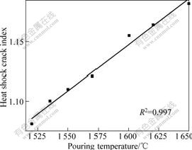
Fig.8 Linear fitting curve of HSCI and pouring temperature
It is known from analyses above that, HSPI and HSCI are greater with higher pouring temperature, and their relationships can be fitted to be linear. In Eq.(13) and Eq.(14), the relationships between pouring temperature and HSPI and HSCI are linear too, which means that the simulation results agree with theory analyses.
4.3 Influence of die temperature before heat shock on HSD factors
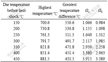
The die temperature before heat shock of 150, 200, 250, 300, 350, 400 and 450 ℃ were chosen; ITR was 1×10⁻⁴m2?℃/W; and the pouring temperature was 1 520 ℃. Table 3 shows the simulation results.
Table 3 Influence of die temperature before heat shock on HSD factors
The fitting curves of relationships between die temperature before heat shock and HSD factors by Origin Lab software are shown in Fig.9 and Fig.10.
It is known from these analyses that, HSPI and HSCI are greater with higher die temperature before heat shock, and their relationships can be fitted to be cubic curves. When the die temperature before heat shock is greater than 150 ℃ in this simulation, HSPI is greater than 1, so this temperature should be within rational range, too low or too high is both bad for die.
4.4 HSD during coat spraying
During non-solid near-net forming process, the coat spraying pressure was about 0.3 MPa; the heat exchange coefficient was 30 000 W/(m2?℃); ITR was 1×10⁻⁴m2?℃/W; pouring temperature was 1 520 ℃; die temperature before pouring was 200 ℃; and coat temperature was 20 ℃. The simulation result is shown in Fig.11.

Fig.9 Cubic fitting curve of HSPI and die temperature before heat shock
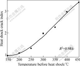
Fig.10 Cubic fitting curve of HSCI and die temperature before heat shock
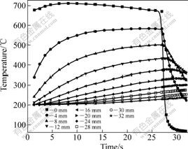
Fig.11 Die temperatures during coating spraying
It is known from Fig.11 that, temperature on cavity surface falls down to 80 ℃ from very high temperature, and the greatest temperature difference reaches 600 ℃. HSPI and HSCI reach 0.852 and 0.730 respectively. So, although the heat shock does not cause die failure directly, heat fatigue failure would be induced.
5 Experiments verification
During squeeze casting of 45 steel[14], with forming pressure of 150 MPa, pouring temperature of 1 520-1 535 ℃, die temperature before heat shock of 200℃ and diatomite coat, HSPI and HSCI are 1.012 and 0.957 1 respectively, and the theoretical values are 1.066 and 0.984 1, respectively; HSPI and HSCI after coat spraying are 1.012 and 0.957 1. Then plastic deformation and crack happen on die cavity under repeated actions of alloy pouring, filling and coat spraying, which are shown in Fig.12 and Fig.13.
When the forming times is 34, the average die temperature reaches 345 ℃. The HSPI at cavity surface reaches 2.117 and that 22.4 mm away from cavity surface is 1.071 where heat shock stress is close to die yield strength, which leads to plastic deformation on cavity moving inside, and the place that is 22.4 mm away from cavity surface is elastic-plastic switching place. Great stress would happen at this position, which leads to spallation failure as shown in Fig.14 under repeated forming.
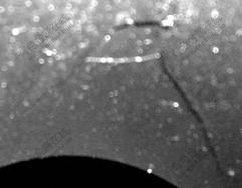
Fig.12 Cracks on cavity surface

Fig.13 Cracks at cavity bottom

Fig.14 Spallation failure of die
6 Conclusions
1) Two dimensionless parameters that are ratios of heat shock stress to die yield strength and to tensile strength, named heat shock plastic deformation index Ωs (HSPI) and heat shock crack index Ωb (HSCI), were chosen as heat shock damage factors. Trend that Ωs and Ωb are close to 1 means the trend of plastic deformation and crack occurring. If Ωs<1 and Ωb<1, no failure would happen; if Ωs>1 and Ωb<1, plastic deformation would happen; if Ωb≥1, fracture induced would occur.
2) The influence rules of heat shock damage factors were as follows. The factors were less with greater interfacial thermal resistance, which were fitted as exponential curves; they were greater with higher pouring temperature, which were fitted as lines; and were greater with higher die temperature before heat shock, which were fitted as cubic curves.
3) During non-solid near-net forming process, heat shocks of pouring, filling and coat spraying were fundamental reasons for early cavity failures. Coat that didn’t fall off with good heat insulation property was important for improving die service environment. With greater forming pressure, part quality is better, but interfacial thermal resistance is smaller, so greater forming pressure is deleterious to die. That is to say, as long as forming requirements are met, the smaller forming pressure is better for die.
References
[1] CHEN Ping-chang, XIONG Guo-qing. Effects of graphite and carbide on resistance to thermal shock property of austenitic cast iron with a 20% nickel content [J]. Journal of Huazhong University of Science and Technology, 1989, 17(1): 71-75. (in Chinese)
[2] MING Wen-long, ZHANG Jing, XIAO Jiang-zhong. An investigation on the thermal quenching features of Ti(C,N) based ceramets [J]. Aerospace Materials and Technology, 1996, 26(4): 33-35. (in Chinese)
[3] PUFF H, LU Hua. Thermal-shock property of SiC(I): Definition of thermal-shock property and its testing method [J]. Foreign Refractories, 1990, 15(9): 33-36. (in Chinese)
[4] WU Jie-zheng. Study on mechanism of high heat shock of tungstic acid tantalum ceramic [J]. Journal of Northwest University of Light Industry, 1990, 8(2): 44-51. (in Chinese)
[5] DAVID J G. An introduction to the mechanical properties of ceramics [M]. Press Syndicate of the University of Cambridge, 1998.
[6] AL-HUNITI N S, AL-NIMR M A. Behavior of thermal stresses in a rapidly heated thin plate [J]. J Thermal Stresses, 2000, 23: 293-307.
[7] STEVERDING B, DUEL H P. Laser-induced shocks and their capability to produce fracture [J]. Journal of Applied Physics, 1976, 47(5): 1940-1945.
[8] ZHANG Yan-hua, FANG Yong-gang, GU Lan. Thermal shocks of high engergy beam welding on materials [J]. Electric Welding Machine, 2005, 35(7): 23-25. (in Chinese)
[9] YANG Shi-ming. Basis of heat transfer [M]. Beijing: Higher Education Press, 2002. (in Chinese)
[10] JIA Li, FANG Zhao-hong, QIAN Xing-hua. Advanced heat transfer [M]. Beijng: Higher Education Press, 2003. (in Chinese)
[11] ZHAO Heng-hua, GAO Xing-jun. ANSYS software and its application [J]. Manufacturing Automation, 2004(5): 20-22. (in Chinese)
[12] ZHANG Bo, SHENG He-tai. Principle of ANSYS finite element numerical analysis and its engineering application [M]. Beijing: Hsinghua University Press, 2005. (in Chinese)
[13] AN Xiao-wei, WANG Cheng-zhi, SONG Guang-sheng. Deal with interface heat resistance in FE analysis of cast solidification temperature field [J]. Chinese Journal of Computational Mechanics, 2005, 22(1): 100-103. (in Chinese)
[14] ZHANG Mi-lan, XING Shu-ming, XIAO Li-ming, LIU Wen, ZHANG Lin, BAO Pei-wei. Design of die for 45 steel valve body in extruded casting [J]. Special Casting and Nonferrous Alloys, 2006(7): 433-436. (in Chinese)
(Edited by YUAN Sai-qian)
Foundation item: Project(2009ZX04014-072) supported by National S & T Major Project of China; Project(Z09000400950901) supported by Beijing Municipal Science and Technology Development Program
Corresponding author: ZHANG Mi-lan; Tel: +86-10-82415140, E-mail: zhang_milan@126.com

