J. Cent. South Univ. Technol. (2008) 15: 853-859
DOI: 10.1007/s11771-008-0157-x
Micro-process model of hydraulic shock absorber with
abnormal structural noise
SHU Hong-yu(�����), ZHANG Wei-wei(��ΰΰ), FENG Yu(�� ��)
(College of Mechanical Engineering, Chongqing University, Chongqing 400044, China)
Abstract: In order to discover the causes of the abnormal noise of shock absorbers, it is necessary to identify the operating characteristics of the shock absorbers. A micro-process model for operation of the hydraulic shock absorber was presented. A novel concept, which describes the process of hydraulic shock absorber by dividing it into smaller steps, was proposed. The dynamic model and the differential equations were established. The results of numerical simulation agree well with data obtained from the vibrostand test, indicating that the collision between the piston and the oil, the alternation of static friction and sliding friction acted between the piston and the cylinder, and the adherence between valve plate and piston result in impact on the piston head near the top dead center and the bottom dead center. Ultimately, the impact excites the high-frequency vibration of the piston structure, which can generate the abnormal noise in the hydraulic shock absorber after its transfer. And the maximum vibration acceleration on the piston head and the abnormal noise increase with the increase of the gap between the oil and piston rod head, the maximum static friction force and the adhering function, respectively.
Key words: shock absorber; abnormal noise; micro-process; clearance impact; simulation
1 Introduction
Although some main noise sources in automobiles have been well controlled in recent years, the abnormal noise of the automobile hydraulic shock absorber, which reduces the quality and decreases the sales volume of automobiles, has become remarkable. The causes of the abnormal noise of hydraulic shock absorber have not been well explained by theory. There is no effective method to control it. Therefore, many researchers have studied the abnormal noise of hydraulic shock absorber.
The abnormal noise of hydraulic shock absorber includes friction noise, air current noise, liquid current noise and structural noise, and the structural abnormal noise is the most notable and the most difficult to attenuate[1]. The abnormal noise referred in this work is structural abnormal noise. Plenty researches and experiments indicate that the abnormal noise is related to the high-frequency vibration ranging from 100 to 450 Hz on the piston rod assembly, and the high-frequency vibration mostly takes place at the moment of the alternation of rebound travel and compression travel[2-7].
Some researchers discussed how and why the impacts are produced. Japanese scholars studied the change of stress on the valve plates of the piston in the shock absorber by using strain gauge measurement methods. They also discussed the influence of adhering function between the valve plates and piston[8]. ZHANG and YU[4] investigated the empty travel impacts caused by the external characteristics distortion of the shock absorber[4]. A non-parameter mathematical model of the shock absorber based on Bouc Wen��s hysteresis model was given in Ref.[5]. But there was no more detailed description about the process of the impacts and how the special wave of acceleration on the piston head has been developed.
In order to discover the causes of the structural abnormal noise, the hydraulic shock absorber operation was divided into micro-process. A non-linear mathematical modeling was carried out by analyzing the impact due to clearance between the piston and the fluid, the alternation of static and sliding friction forces between the piston and the cylinder, and the adhering friction caused by valves and piston.
2 Structural and dynamic model of hydraulic shock absorber
2.1 Structure and working principle of hydraulic shock absorber
Although the operation of hydraulic shock absorber during the movement of automobile is very complex and stochastic, yet it can be divided into alternate rebound stroke and compression stroke[9]. It has been testified that the abnormal noise can be arisen in a vibrostand test of the hydraulic shock absorber, which is excited by a sine excitation with constant amplitude. So the stand test can be used in the analysis of the process of the hydraulic shock absorber to find out the causes of the abnormal noise. The typical structure of hydraulic shock absorber is shown in Fig.1.
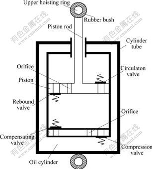
Fig.1 Structure of hydraulic shock absorber
The hydraulic shock absorber consists of a cylinder, a rod with a piston, a reservoir tube and valves. A compensating valve and a compression valve with a spring are arranged in the lower part of the cylinder. There is a ring attached to the frame bracket at the upper end of the rod. The piston carries a compression relief valve and a rebound valve with spring. There are a hoisting ring and a rubber bush at the bottom of the reservoir tube and the top of rod. And the working principle is as follows: when the shock absorber is compressed, the piston goes down and the fluid is compressed to flow through the orifice and the circulation valve into the chamber above the piston. Since the rod occupies more and more space of the chamber above the piston, the amount of fluid is larger than the capacity of the upper chamber and part of it has to overcome the resistance of the compression valve spring, passes through the compression valve and orifice, finally goes to the oil cylinder. When the shock absorber is stretched, contrarily, pressure is developed in the chamber above the piston. This pressure closes the compression relief valve and opens the rebound valve in the piston. The fluid flows through the orifice and the rebound valve in the piston to the chamber under the piston. Besides, part of the fluid returns from the oil cylinder through the compensating valve into the same chamber. During the alternation of the rebound and compression travel, the pressure difference between the upper and lower chambers generated by the resistance of the valves and passages to the fluid because of the reciprocating motion of the piston ensures the required damp for the absorber[10-11].
The hydraulic shock absorber is mounted on the supporting shaft of automobile or test stand by the hoisting ring with rubber bushes that are used to attenuate the high-frequency vibration. And the deformation of the rubber bushes, which can be ignored in the dynamic analysis of whole vehicle, should be taken into account for the analysis of the abnormal noise in the hydraulic shock absorber[12].
2.2 Vibrostand test on hydraulic shock absorber
Especially, in order to investigate the vibration of the piston rod subjected to a sine excitation with constant amplitude in the stand test on the hydraulic shock absorber, the test can be simplified as the dynamic model shown in Fig.2[13-14].

Fig.2 Dynamic model of hydraulic absorber in stand test
In Fig.2, m denotes the mass of the piston head assembly; x is the displacement of the piston head; k is the stiffness of the rubber bushes; c is the coefficient of damping; Fc represents the force and friction acted between the piston head and the fluid flowing in the cylinder tube; xr is sine excitation; A0 is the amplitude of sine wave; �� is the angular frequency of the excitation.
In the stand experiment the absorber is subjected to the sine wave excitation, the acceleration of the piston rod head in the hydraulic shock absorber is illustrated by a typical damping curve shown in Fig.3. The frequency of the damped wave is close to that of a single degree of freedom system constructed by a parallel combination of linear spring and piston. It should be noted that the shapes of the acceleration curves of the piston rod in the normal and abnormal shock absorbers are similar, and the only difference is their amplitudes. Besides, the interval between the start point of the damping acceleration curve and the dead center in abnormal shock absorber is longer than that in normal shock absorber. According to the results of the experiment, it can be concluded that the structural abnormal noise must be related to some discrete impacts at the alternation of rebound stroke and compression stroke.
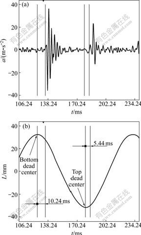
Fig.3 Vibration acceleration curves on piston head (a) and corresponding phase of piston vibration (b)
By the theory of vibration, the differential equation of vibration of the piston head in hydraulic shock absorber can be written as
 (1)
(1)
Although the differential equation seems very simple, it is very complicated to adjust the force Fc during the hydraulic shock absorber operation. In order to thoroughly analyze the process of the impacts on the piston, the cycle process of the hydraulic shock absorber was divided into 10 states. The change and expression of Fc in each state was discussed as follows.
3 Micro-division of operation cycle of hydraulic shock absorber
The working cycle of the hydraulic shock absorber is very complex, especially in high frequency. There are many factors that can affect the vibration and impact in the hydraulic shock absorber, such as the elasticity and damping of the ring with rubber bushes, the fluid vaporization and its compressibility, the clearance impact between the fluid and piston rod head, the inertia of the piston and the rod, the friction between the piston and the cylinder, opening lingeringly and closing ahead of the valves, and the adhering function between the valve plate and the piston, etc.
The micro-division of the working cycle of the hydraulic shock absorber is shown in Fig.4. And the motion state of piston and cylinder at each step is shown in Fig.5.

Fig.4 Micro-process of absorber operation
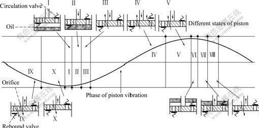
Fig.5 Schematic drawing of hydraulic shock absorber piston at each state
State�� As the rebound stroke ends, the piston moves near the top dead center of the cylinder tube. Then the relative velocity between the piston and the cylinder tube falls to zero due to the adhering function. This status is defined as the first state. During this state, the fluid cannot fill the chamber under the piston in time, and the pressure in the chamber under the piston is lower, so the fluid vaporizes. The fluid overflows from compression valve due to the inertia. So there exits a small gap between the piston and the fluid in the chamber under the piston. At the beginning of this state, piston and cylinder move downward together, while the upper rubber support spring arranged at the top of the cylinder is slightly stretched. As the velocity of the cylinder reduces and finally reverses, the upper rubber support spring is compressed. In this state, the movements of piston and cylinder are in accord with each other due to the adhering function. In the meantime, the fluid is not in contact with the piston due to the gap, so the static friction force between cylinder and piston is the only force acted on the piston, which is:
 ��Ff0
��Ff0
(2)
where the initial displacements of the cylinder and the piston are given by xr0 and x0, respectively; the static friction force is denoted by fs, and Ff0 represents the maximum static friction force.
State �� When State��is about to end, the support rubber is stretched gradually. And the elastic force k(xr-xrb+xb) increases gradually along with the rising movement of the cylinder. Then the motion state of piston and cylinder gets into State ��, Fc reaches Ff0, the relative static between the piston and the cylinder changes to relative sliding, and the static friction force falls to smaller sliding friction force. The piston moves downward by the elastic force of rubber spring, and the gap between the piston and the fluid in the chamber under the piston is filled gradually, finally the piston and the fluid in the chamber under the piston impacts with each other. It is similar to water-hammer impact effect in hydraulic system. The process of the solid-fluid impact is extremely complex. In order to simplify computation and simulation, the impact is considered only once in this work, and it is assumed that the chamber is filled with ideal gas, which can be compressed rapidly. So, in this condition, there exists
 (3)
(3)
where fd represents the force of sliding friction between the piston and the cylinder; cross-sectional area of the piston is denoted by S. The initial and the instantaneous gaps between the piston and the fluid in the chamber at time t are given by ��0 and ��, respectively. The initial displacements of the cylinder and the piston at the beginning of this state are given by xr0 and xr, respectively.
State �� After State �� ends, the fluid in the chamber under the piston starts to flow into the chamber above the piston through the orifice. During this state, the pressure difference between the upper and lower chambers is smaller than that of State ��, and the compression valve is still closed due to the adhering function between the valve piece and the piston. And now there exists

(4)
where cf represents the damping coefficient as the fluid passes the orifice; and  represents the critical damping force between the compression valve plate and piston.
State �� During State ��, with the increase of relative velocity between the piston and the cylinder, the pressure difference between the upper and lower chambers increases. The compression valve plate opens instantaneously once the pressure is higher than the adhering force produced by the piston. State �� begins, the damping force suddenly reduces and there exists a turbulence.
 (5)
(5)
where cc represents the damping coefficient as the fluid flows through the compression valve and the orifice at the same time; and denotes the critical damping force as the compression valve is closed.
State �� Relative velocity between the piston and the cylinder decreases in State ��, and compression valve closes when  ��
�� Fc is the same as that in State ��, namely
 (6)
(6)
where va represents the minimum relative velocity between the piston and the cylinder.
States ��-�� When the compression travel is about to finish, the piston is near the bottom dead center of the cylinder. Then the relative velocity between the piston and the cylinder falls to zero, and the relative movement between the piston and cylinder is relatively geostationary due to adhering action. During the following rebound stroke, the rebound valve works. The motion states of the piston, the changes of Fc and its expressions are the same as those in the compression travel.
4 Simulation and analysis of model
4.1 Target of simulation
According to the dynamic analysis above and the differential equations of motion, the MATLAB program for simulation was compiled[15]. In the simulation, the parameters used in the mathematical model are the same as those in vibrostand test, which are listed in Table 1.
Table 1 Parameters used in mathematic model

For the sake of comparing the results of test and simulation, firstly, the accelerations of vibration on the piston under three kinds of load were computed, which are the impact due to the clearance between the oil and the piston, the alternation of static and sliding friction force acted between the piston and the cylinder, and also the adhering between the valve plate and the piston.
4.2 Effect of clearance impact
The results caused only by the clearance impact between the oil and the piston head are shown in Fig.6. Fig.6(a) shows the curve of the vibration acceleration on the piston head with time when the gap between the oil and the piston rod head is 0.7 mm. Fig.6(b) shows the changes of vibration acceleration as long as the clearance between the oil and the piston rod head changes. It can be seen from Fig.6 that the maximum acceleration of vibration on the piston head increases with the increase of the gap between the oil and the piston rod head. The maximum acceleration increases more slowly when the clearance is from 0 to 0.7 mm than that when the clearance is larger than 0.9 mm, relatively.
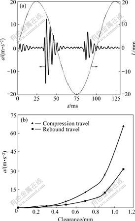
Fig.6 Effect of clearance impact: (a) Vibration acceleration curve and phase of vibration; (b) Peak acceleration��clearance curve
If the series of valves of the shock absorber are not well matched while designing and manufacturing, the oil may fail to fill the gap between the piston and the oil during the alternation of the rebound and compression travel. And the piston will be severely impacted when the gap reaches a considerable extent. The impact will lead to abnormal noise[4].
4.3 Effect of alternation between static and sliding friction force
The results caused only by the alternation of static and sliding friction force between the piston and the cylinder are shown in Fig.7. Fig.7(a) shows the time history of the vibration acceleration on the piston head when the maximum friction force is 0.5 N. Fig.7(b) shows the change of the vibration acceleration on the piston head with the maximum friction force. Obviously, the maximum vibration acceleration on the piston head increases with the increase of the maximum friction force.
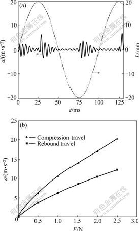
Fig.7 Effect of alternation between static and sliding friction force: (a) Vibration acceleration curve and phase of vibration; (b) Peak acceleration��maximum static friction curve
In application, the piston or the rod may scrub the cylinder or the sleeve when the matching cannot meet the precision need of the assembling in manufacturing. Specially, in the north, the static friction is extremely hard when the shock absorber works in cold weather. It can be seen from Fig.7(b) that the impact acceleration rises rapidly as the static friction goes up, and the noise increases as well[11].
4.4 Effect of adhering function
The results caused only by the adhering function between the valve plate and the piston are shown in Fig.8. Fig.8(a) shows the graph of the vibration acceleration on the piston head with time when the adhering between the valve plate and the piston is 20 N?s/m. Fig.8(b) shows the change of the maximum vibration acceleration on the piston head with the change of adhering function. It illustrates that the vibration acceleration on the piston head increases with the increase of the adhering function. For example, Reynolds number of fluid will change when the temperature is changed. And in the case of shock absorber, the alternation of the seasons will change the characteristic of oil and result in abnormal noise in the absorbers. HIROFUMI et al[16] analyzed the mechanism of the ratting noise generated by the damping force surging using computational fluid dynamic (CFD) method, and it is found that oil adsorption is a main cause of the damping force surging.

Fig.8 Effect of adhering function: (a) Vibration acceleration curve and phase of vibration; (b) Peak acceleration��adhering coefficient curve
In order to obtain the co-operative effect of the three factors mentioned above and to verify the correctness of the method used in this work, further simulation was carried out using the same data as in the stand test shown in Fig.3. The results are approached and plotted in Fig.9.

Fig.9 Vibration acceleration curve (TDC denotes top dead center; BDC denotes bottom dead center): (a) Acceleration curve on piston head; (b) Corresponding phase of piston vibration
As can be seen from the figures, the results of numerical simulation are in accord with the test results, indicating that the method used in this work is feasible.
5 Conclusions
1) The designed structure of the hydraulic shock absorber leads to the impacts on the piston head near the top dead center and the bottom dead center. These collisions cause the vibration of the piston head, which can generate the abnormal noise in the hydraulic shock absorber after its transfer.
2) The high-frequency vibration is caused by the impacts on the piston head, which are resulted from the clearance impact of the oil and piston head, the alternation of static and sliding friction force acted between the piston and the cylinder, as well as the adhering function between the valve plate and the piston.
3) In application, the abnormal structural noise in the hydraulic shock absorber is mainly resulted from the following aspects: the improper fixing of the valves in the absorber that results in a wider gap between the piston and the oil; the errors come from the machining and assembly process; the stronger damp between the valves and piston because of the lower temperature in winter, which makes the vibration of the piston out of limit.
References
[1] YU Da-wei, LUO Jin-liang. An analysis on the cause of abnormal sound of automobile shock absorber [J]. Journal of Weapon, 2000, 21(1): 19-26. (in Chinese)
[2] RUNLING P, JIN J, RALPH O B. Design of an optimal shock-damping isolator with application to casters [J]. Journal of Sound and Vibration, 2006, 289(2): 278-293.
[3] CHAOS C P, SHAW S W. The dynamic response of multiple pairs of subharmonic torsional vibration absorbers [J]. Journal of Sound and Vibration, 2000, 231(2): 411-431.
[4] ZHANG Li-jun, YU Zhuo-ping. Experimental research on the abnormal noise of hydraulic suspension shock absorber [J]. Journal of Vibration and Shock, 2002, 21(1): 13-18. (in Chinese)
[5] SHEKHAR C, HATWAL H, MALLIK A K. Performance of non-linear isolators and absorbers to shock excitations [J]. Journal of Sound and Vibration, 1999, 227(2): 293-307.
[6] YANG Ping, TAN Yong-hong, YANG Jian-min, SUN Nin. Measurement, simulation on dynamic characteristics of a wire gauze�Cfluid damping shock absorber [J]. Mechanical Systems and Signal Processing, 2006, 20(3): 745-756.
[7] TANG Hua-ping, PENG Ya-qing. Optimal design method for force in vibration control of multi-body system with quick startup and brake [J]. Journal of Central South University of Technology, 2005, 12(4): 459-463.
[8] LU Zhen-hua, LI Shi-min. Simulation techniques for nonlinear dynamic characteristics of telescopic hydraulic dampers [J]. Journal of Tsinghua University: Science and Technology, 2002, 42(11): 30-37. (in Chinese)
[9] ZHANG Jun-qing, JIN Da-feng, ZHAO Liu-qi, LI Zhi-guo. A study of non-linear mathematical model of double cylinder vibration damper [J]. Engineering Mechanism, 2002, 33(11): 16-18. (in Chinese)
[10] SCHIEHLEN W, HU B. Spectral simulation and shock absorber identification [J]. International Journal of Non-linear Mechanics, 2003, 38(2): 161-171.
[11] LI Zheng. Reason analysis and simulation investigation of front shock absorber abnormal sound for Chang��an SC6350 [D]. Chongqing: Chongqing University, 2004. (in Chinese)
[12] BLUNDELL M V. The influence of rubber bush compliance on vehicle suspension movement [J]. Materials and Design, 1998, 19 (11): 29-37.
[13] BESINGER F H, CEBON D, COLE D J. Damper models for heavy vehicle-ride dynamics [J]. Vehicle System Dynamics, 1995, 24(1): 35-64.
[14] MOLLICA R, YOUCEF T K. A non-linear dynamic model of a monotube shock absorber [C]// Proceedings of the American Control Conference. Albuquerque, New Mexcico: IEEE Press, 1997: 704-708.
[15] WANG Shao-chun, DENG Zong-quan, HU Ming, GAO Hai-bo. Dynamic model building and simulation for mechanical main body of lunar lander [J]. Journal of Central South University of Technology, 2005, 12(3): 329-334.
[16] HIROFUMI M, MASATO K, HIDEAKI K. Mechanism analysis of shock ratting noise [J]. TOYOTA Technical Review, 1997, 47(1): 96-103. (in Japanese)
Foundation item: Project(200244) supported by the Visiting Scholar Foundation of the State Key Laboratory of Mechanical Transmission, Chongqing University
Received date: 2008-03-12; Accepted date: 2008-04-29
Corresponding author: SHU Hong-yu, Professor, PhD; Tel: +86-23-65103568; E-mail: shycqu@163.com
(Edited by CHEN Wei-ping)

