���ڷǾֲ�λ���ܶȾ�����������Ԫģ�͵Ľ������屡Ĥ���������ص�
��Դ�ڿ����й���ɫ����ѧ��(Ӣ�İ�)2013���11��
�������ߣ��º��� ���滳 �� ٻ �����
����ҳ�룺3362 - 3371
Key words��crystal plasticity; micro-bending; statistically stored dislocations; geometrically necessary dislocations
ժ Ҫ�����ÿ��ǷǾ����۽ṹ�ķǾֲ�λ���ܶȾ�����������Ԫģ�ͣ��о��������屡Ĥ�����������Ա��ε��ص㡣��ģ�Ͳ���ͳ�ƴ洢λ���ܶȺͼ��α���λ���ܶ���Ϊ���ڲ�״̬������ͨ�����α���λ���ܶȵ��ݻ���Ԥ�ⵥ���������Ĥ���������е�Ӧ���ݶ�ЧӦ�����ò�ͬ������С��CuZn37 ��-��ͭ�ྦྷ�屡Ĥ��������ʵ�飬�����������������κ��Ӳ�ȷֲ�ͼ����ģ��õ���λ���ܶȷֲ���ʵ���õ�Ӳ�ȷֲ����жԱȣ����ִ־�������ϸ������Ӳ�ȷֲ��IJ�ͬ��Ҫ����ͳ�ƴ洢λ���ܶȺͼ��α���λ���ܶ�����ġ������������������о��������ε��ص��λ���ܶȵ��ݻ���
Abstract: A non-local dislocation density based crystal plasticity model, which takes account of the microstructure inhomogeneity, was used to investigate the micro-bending of metallic crystalline foils. In this model, both statistically stored dislocations (SSDs) and geometrically necessary dislocations (GNDs) are taken as the internal state variables. The strain gradient hardening in micro-bending of single-grained metal foils was predicted by evolution of GNDs. The predicted results were compared with the micro-hardness distribution of the previous micro-bending experiments of CuZn37 ��-brass foils with coarse grains and fine grains. Comparison of the simulated dislocation densities distribution of SSDs and GNDs with the experimental results shows that different micro-hardness distribution patterns of the coarse and fine grain foils can be attributed to the corresponding SSDs and GNDs distributions. The present model provides a physical insight into the deformation mechanism and dislocation densities evolution of the micro-bending process.
Trans. Nonferrous Met. Soc. China 23(2013) 3362-3371
Hai-ming ZHANG1, Xiang-huai DONG1, Qian WANG1, He-zong LI 2
1. National Die and Mould CAD Engineering Research Center, Shanghai Jiao Tong University, Shanghai 200030, China;
2. Department of Mechanical and Electrical Engineering, Hebei University of Engineering, Handan 056038, China
Received 4 January 2013; accepted 30 January 2013
Abstract: A non-local dislocation density based crystal plasticity model, which takes account of the microstructure inhomogeneity, was used to investigate the micro-bending of metallic crystalline foils. In this model, both statistically stored dislocations (SSDs) and geometrically necessary dislocations (GNDs) are taken as the internal state variables. The strain gradient hardening in micro-bending of single-grained metal foils was predicted by evolution of GNDs. The predicted results were compared with the micro-hardness distribution of the previous micro-bending experiments of CuZn37 ��-brass foils with coarse grains and fine grains. Comparison of the simulated dislocation densities distribution of SSDs and GNDs with the experimental results shows that different micro-hardness distribution patterns of the coarse and fine grain foils can be attributed to the corresponding SSDs and GNDs distributions. The present model provides a physical insight into the deformation mechanism and dislocation densities evolution of the micro-bending process.
Key words: crystal plasticity; micro-bending; statistically stored dislocations; geometrically necessary dislocations
1 Introduction
With the rapid development of microsystems (MST) and microelectromechanical systems (MEMS), microparts are widely used in diverse fields, especially in micro electronic technology, sensor technology and medical equipment. The significant progress has been made in the fabrication of microparts via various methods [1,2]. Microforming, which is metal forming at the microscale, is a promising technology to manufacture these small metallic parts of MST/MEMS, in particular for mass production, for its well-known advantages of high production rate, efficient material utilization, and low costs [2-6]. For example, micro-bending can be serve as a prospective manufacturing method for the miniaturized components such as contact springs and micro-connectors [7]. There has been increasing interest in the investigation on the plastic behaviors, mechanical properties and formability at micro and nanoscale to design, fabricate and enhance the reliability of MST/MEMS structures [8-14].
Because the material microstructure lengths, such as grain size and Burgers vector, do not decrease with the decrease of the specimen sizes, metallic materials exhibit strongly size dependent mechanical behavior. A typical size effect in microscale deformation is the strain gradient strengthening effect resulting from the macroscale inhomogeneous deformation, which is observed in the micro-bending experiments [15], nano/micro-indentation experiments [16], and torsion experiments [17]. The conventional material models and knowhow in macroscale are no longer valid or accurate in micro-forming due to size effects [6,18]. During the last two decades, there have been significant efforts to develop new plasticity theories to describe these strain gradient effects. Two representative classes of the plasticity theories are: 1) the phenomenological strain gradient plasticity theory proposed by FLECK and HUTCHINSON [19]; 2) the mechanism-based strain gradient (MSG) plasticity theory developed by GAO et al [20]. These strain gradient theories inspire lots of material models for the investigation on the micro-bending. LI et al [21,22] modified Nix-Gao model to investigate the effect of strain gradient on the springback behavior in micro-bending process.
However, due to the phenomenological nature, the strain gradient plasticity theories fail to describe size effects related to the microstructural inhomogeneity, such as the influence of grain orientation, grain size and grain boundaries (GBs). In micro-forming, there are fewer grains in the deformation area. Therefore, individual grains dominate the deformation and inhomogeneous deformation becomes more significant, which result in the grain statistics dependent size effects [23]. The micro-bending of metallic polycrystalline depends on the associative effects of strain gradient, grain size, grain orientation and GBs [13]. Non-local physical and micromechanical concepts are required to obtain an appropriate prediction of the mechanical behavior of micro-bending.
Crystal plasticity theory, based on the slip systems level of individual grains, provides a suitable multiscale frame for the investigation of the inhomogeneous deformation of micro-forming. Since the pioneering work of ASARO and RICE [24], the methods of crystal plasticity work well for solving problems of metal forming, such as inhomogeneous plastic deformation, FLC prediction and texture evolution [25-27]. The traditional crystal plasticity models are competent for describing the influence of grain orientation and individual grains, however, more physical mechanisms are needed to be taken into account, for the studying of the above size effects.
In this work, a non-local dislocation density based crystal plasticity model, introducing the evolution of SSDs and GNDs, is developed with the aim to investigate the deformation characteristics of micro- bending. The model is implemented into the commercial finite element software ABAQUS/Explicit by writing the user subroutine VUMAT. It is adopted to investigate the recently reported micro-bending experimental results of PARASIZ et al [28] and LI et al [29]. It is found that the micro-hardness distribution of the coarse grained foils deviates from that of the fine grained foils, and the present non-local model makes attempt to show the insights of the physical mechanism of such phenomena.
2 Theory
2.1 Finite deformation crystal plasticity model
In the present work, the kinematics of crystal plasticity model is established in the hyperelastic frame. The multiplicative decomposition of the total deformation gradient F can be expressed as [27]
 (1)
(1)
where Fe is the elastic distortion and rigid body rotations of lattice; Fp is the plastic contribution arising solely from the dislocation motion in the intermediate configuration. The multiplicative decomposition of deformation gradient leads to the additive decomposition of the velocity gradient as
 With
With  (2)
(2)
The plastic part of the velocity gradient due to crystallographic slip is expressed as
 with
with  (3)
(3)
where  is the slip rate of a slip system;
  ,
,  and
and  are the vectors represent the slip direction, the normal direction and the Schmid resolved tensor of a slip system, defined in the intermediate configuration, respectively.
The second Piola-Kirchhoff stress T is related to the elastic Green strain tensor Ee as
 with
with  (4)
(4)
where C is the fourth order anisotropic elastic tensor. For the cubic crystals, it can be specified in terms of three independent elastic constants C11, C12 and C44 in the local coordinate systems. The Cauchy stress tensor �� in the current configuration is related to T as
 (5)
(5)
The resolved shear stress can be expressed as
 (6)
(6)
where is the driving force that prompts the massive dislocation lines to glide on the specific slip plane, i.e., serves as the bridge between crystal plasticity and dislocation densities. Details in the derivation of the present crystal plasticity model adopted in this work can be found in Ref. [27].
2.2 Dislocation density based material model
2.2.1 Flow equation and hardening equation
It is assumed that plastic deformation is mainly due to the glide of dislocations, and the movement of dislocations is impeded by both short-range and long-range barriers. The short-range barriers can be overcome by the help of thermal activation; however, the long-range barriers are athermal, which can only be surmounted by the assist of externally applied force. Based on the thermally activated mechanisms of dislocation motion, the relationship between plastic slip rate and dislocation density can be defined by the Orowan equation combined with the Arrhenius-type law as [30,31]
 (7)
(7)
where kB is the Boltzmann constant; T is the absolute temperature; ��G0 is the activation energy necessary to overcome the lattice resistance in the absence of any external force; The parameters p and q determine the shape of the energy barriers, such as sinusoidal or hyperbolic [30]; is the resolved shear stress defined in Eq. ;  is the long-range resistance, which describes the work hardening, includes the elastic stress field due to GBs, far-field forest of dislocations, and other structural defects;
  is the mechanical stress required to cross the barriers without any thermal activation.
Considering the enhanced strengthening of GNDs,  can be expressed by a Taylor-type relationship as follows
 (8)
(8)
 (9)
(9)
where A���� is the interaction matrix, defining the mutual hardening of forest dislocations between each pair of slip systems. Based on the types of interactions and the symmetry of FCC crystals, FRANCIOSI [32] suggested that A���� is governed by six hardening coefficients, g0�Cg5. g0 describes the in-plane interaction of dislocations with the same Burgers vector; g1 describes the interaction of dislocations with different Burgers vectors but on the same gliding plane; g2�Cg5 describe the out-of-plane interactions and are related to four different types of junctions/locks. They are the Hirth junction, collinear lock, glissile junction, and Lomer junction, respectively. �� is the temperature dependent shear modulus, which can be described as
��=[C44(C11�CC11)/2]�C1/2 (10)
In Eq. (9),  ,
, and
and  are the densities of total dislocation, SSDs and GNDs, respectively. In this work, GNDs mainly obstruct the movement of dislocations, and then increase the slip resistance.
2.2.2 Evolution of SSDs
The evolution of SSDs is described as [33]
 (11)
(11)
The first term represents the multiplication of dislocations, which is due to the grain boundary sources and the mutual trapping of stochastic distributed dislocations; the second term describes the dislocations mutual annihilation. Where D is the average grain size; M���� is the interaction matrix, defining the mean free path that the dislocations travel before being stored, and it is assumed that M���� is identical to A����; yc is the critical annihilation distance.
2.2.3 Evolution of GNDs
The classical crystal plasticity cannot pick up size dependent behavior, and it can be extended to account for the size effects of microscale deformation by introducing geometrically necessary dislocations. GNDs maintain the lattice curvatures in the inhomogeneous plastic deformation. Based on the multiplicative decomposition of the deformation gradient, CERMELLI and GURTIN [34] derived, as a measure of GNDS, a tensor field G that may be described using the plastic field Fp through the relations [34,35]

where �� is the material curl tensor field defined by (��T)IJ=eIRS TJS/XR (in material components), eIRS is the alternating symbol;
  is the tangential direction of dislocations;
  is the slip direction. The material time derivative of tensor field G is derived as
 (13)
(13)
where  . Using Eqs. (3) and (13), we obtain
 (14)
(14)
 (15)
(15)
The scalar dislocation densities can be obtained by the projection of  as
as
 (16)
(16)
 (17)
(17)
 (18)
(18)
where  is screw dislocation component;
  is edge dislocation component with the tangential direction perpendicular to both the slip direction and normal of �� slip system;
  is edge dislocation component with the tangential direction parallel to normal of �� slip system. The total GNDs of �� slip system is written as
 (19)
(19)
It is obvious that the material coordinate derivation of the slip rate and plastic deformation gradient Fp are needed, in order to calculate  . Such high order gradient of displacement is troublesome in the current commercially FEA software [35]. Here, the mesh free method of moving least squares (MLS) is adopted to calculate the high order gradient field of the Gauss points, that is
 (20)
(20)
where I is the number of the adjacent Gauss points in the local domain of the current Gauss point, T is target variable; ��I and T I are shape function derivation and target variable values of the adjacent Gauss points. The detail derivation can be found in Ref. [36]
The above mesoscopic material model is implemented into ABAQUS/Explicit by the user subroutine VUMAT, the integration scheme refers to Ref. [27].
3 Experiment and numerical simulation
In this work, the simulations of micro-bending of single crystalline foils with different thickness, as well as the simulations and experiments of polycrystalline micro-bending with different grains across the thickness, are presented.
3.1 Experimental procedure
Figure 1(a) shows CCD image of the micro-bending experimental setup. The foils�� thickness t=200 ��m; the ratio of the punch and die radii to the thickness of foils is 2.5t; the clearance between the die and punch is designed as 1.2t, which is slightly larger than the foil��s thickness in order to prevent the foil from being squeezed. The experimental material is CuZn37��-brass, the average grain sizes of coarse grain foil and fine grain foil are 128 and 39 ��m, respectively [29].
3.2 Finite element model for the simulation
The finite element model for the simulations of micro-bending is shown in Fig. 1(b), which consists of a fixed rigid die and holder, a moveable rigid punch and the deformable blanks. The tools�� parameters are the same as the experiments; the velocity of punch is 0.1 mm/s. The process is modeled as a plane strain problem.
For the case of single crystal model, the blanks are assigned by three different thicknesses, i.e. 50, 100 and 200 ��m; and the blanks are divided by 100��25 C3D8R elements. All the elements are assigned by the ideal cube orientation, i.e., the Bunge Euler angles are ��1=0��, ��=0��, ��2=0��.
For the case of polycrystalline with coarse grains, there is only one grain across the thickness, eight grains along the length, and the foil is divided by 250��35 C3D8R elements. For the case of polycrystalline with fine grains, there are six grains across the thickness, is grains along the length, and the foil is divided by 250��75 C3D8R elements. The grain size is assumed to be identical in each case, and the grain orientations are randomly read from the texture sample file. The initial bending foils are shown in Fig. 2, and the corresponding {111} pole figures of the grain orientations are shown in Fig. 3.
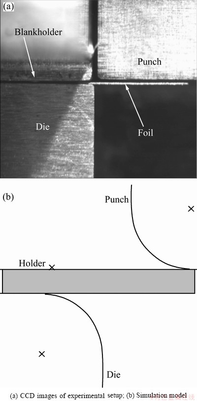
Fig. 1 Micro-bending model

Fig. 2 Geometry of micro-bending polycrystalline foils
3.3 Material parameters for present model
Theoretically, the ideal physically based models should not contain fitted parameters. However, due to the less understanding of some aspects of plastic deformation mechanism, the present dislocation density based model still has some empirical or fitting parameters. The certain and empirical material constants are: b=0.256 nm, C11=205 GPa, C12=117 GPa, C44=44 GPa, kB=1.38��10 J/K, T=300 K, ��G0=0.2 ��b3, p=0.5, q=1.5,  =1��108 s-1 [30], g0=0.1, g1=0.22, g2=0.3, g3=0.38, g4=0.16, g5=0.45 [33]. The fitted parameters are =28 MPa, dislocation multiplication coefficient K=26/b m-1, and the critical dislocation annihilation distance yc=8b. The reference stress-strain curves used for identification the material parameters are taken out from Ref. [1], and the integration point consists of 200 grains with random orientation.

Fig. 3 {111} Pole figure of initial foils
The stress-strain curves of experiment and simulation are shown in Fig. 4, where �� is the similar factor [1]. It can be found that the dislocation density based crystal plasticity model with present material parameters shows good agreement with the experimental data. The prediction of the stress-strain response is not the concern of present work. The above fitting material parameters are adopted for the latter simulation of micro-bending.
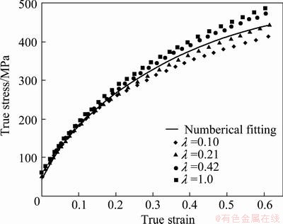
Fig. 4 Stress-strain curves of experiment and simulation
4 Results and discussion
4.1 Micro-bending of single crystalline specimens
In the micro-bending process, the strain gradient inherently exists due to the curvature of the bent specimen, and the plastic strain gradient directly corresponds to GNDs density. The accumulation of GNDs increases the slip resistance of the movement of dislocations, which results in the size effect of ��smaller is stronger��. For the single crystal micro-bending, the specimen is absolutely homogeneous. The incompatibilities and the corresponding GNDs storage are induced only by the macroscopic strain gradient.
Figure 5 shows the predicted normalized bending moment versus the relative displacement, where the normalized bending moment and relative displacement are represented as M/t2/w (w=0.025t is the width of specimens) and D/t, respectively. It can be found that the proposed model successfully describes the thickness dependence of the normalized bending moment. As the thickness equals 500 ��m, the normalized bending moment approximates to that of classical local model. It is concluded that the strengthening effect of strain gradient can be ignored when the thickness of the bent specimen is larger than 500 ��m.
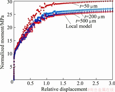
Fig. 5 Normalized bending moment�Crelative displacement relation of single crystalline micro-bending
Figures 6-8 show the density distribution of SSDs, GNDs and the total dislocation (SSDs+GNDs), respectively, of the specimens with thickness of 200 and 50 ��m. According to Fig. 6, it can be found that the distribution of SSDs almost does not depend on the thickness of specimens but mainly on the distribution of strain. In both specimens, a large amount of SSDs are stored in the surfaces, but sharply decrease towards the neutral plane. However, as shown in Fig. 7, the magnitude and distribution of GNDs are relatively sensitive to the thickness. Besides, the accumulation of GNDs in the neutral plane is slightly higher than that near surfaces, and this phenomenon is more evident for the thinner specimen. Figure 8 shows the density distributions of total dislocations, as the thickness decreases, more dislocations accumulate near the neutral plane, though the maximum dislocation density still appears near the surfaces. MOTZ et al [37] carried out the micro-bending tests of copper single crystal with thickness ranging from 1 to 8 ��m, and pointed out that the dislocation should accumulate near the neutral plane of the specimen, which causes the size effect. Therefore, MOTZ et al��s interpretation of the size effect in micro-bending is basically the same as that obtained from the present simulation as discussed above. Furthermore, it is concluded that such accumulation of dislocation density towards the neutral plane is mainly due to GNDs.
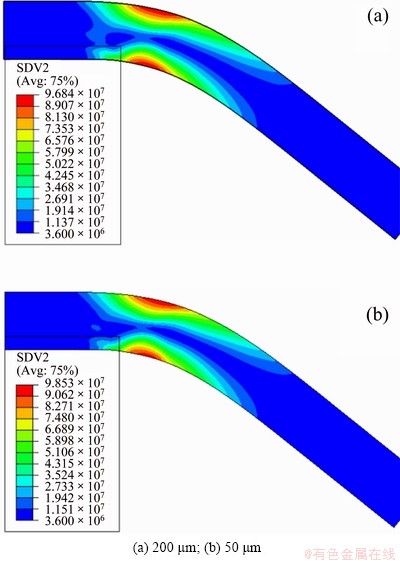
Fig. 6 SSDs contours of bent foils with different thickness
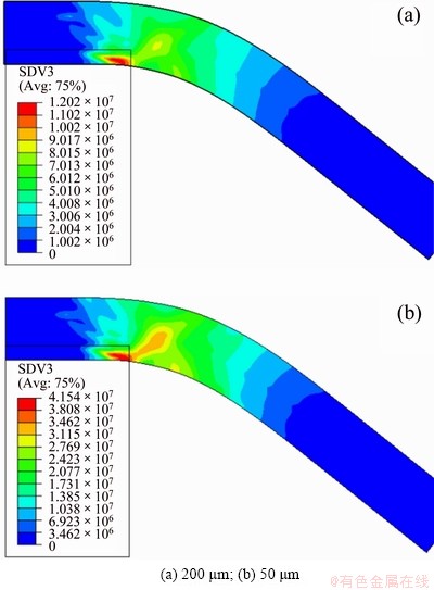
Fig. 7 GNDs contours of bent foils with different thickness
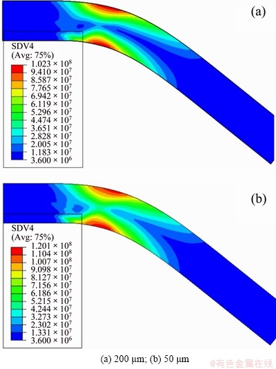
Fig. 8 Total dislocation (SSDs+GNDs) contours of bent foils with different thickness
4.2 Micro-bending of polycrystalline specimens
The mechanical behavior of polycrystalline micro- bending is substantially different from that of single crystal, because of the additional effects of the grains�� mis-orientation and GBs. Our previous micro-bending experiments of CuZn37 ��-brass foils indicate that the micro-hardness distribution of coarse grain foil is very different from that of fine grain foil [29], as shown in Fig. 9. From Fig. 9(a), the contour plot of the coarse grained specimens is scattered, which is anomalous to macroscale bending. From Fig. 9(b), it can be seen that the hardness contour plot of the fine grain foil has a smooth and consistent layered pattern through the thickness and along the length of the specimens, which is consistent with conventional bending. The hardness is the lowest at the neutral axis in the center of the specimen, and a broader soft inner layer appears. The similar phenomena can also be found in Ref. [28].

Fig. 9 Martens hardness of CuZn37 foils after bending
As the carrier of plastic deformation, dislocation density has direct correlation with plastic strain, as well as the work hardening. Figures 10(a) and (b) show SSDs distribution of coarse grain and fine grain foils. It can be found that the generation of SSDs in grains with different orientation is quite different from that of the coarse grain foil. However, for the fine grain foil, the most grains near two surfaces have relatively high SSDs.
GNDs maintain the compatibility of deformation when there is nonhomogeneous plastic deformation. According to Figs. 11(a) and (b), it can be found that a significant number of GNDs are stored in the vicinity of GB, for both cases of coarse grain and fine grain. There is also some aggregation of GNDs in the interior of grains, nevertheless, the magnitude is relatively small. It is concluded that GNDs produced by microstructure inhomogeneity are more prominent than that produced by macro strain gradient for the metallic polycrystalline foil under micro-bending process. That is, the grain size and orientation have prior influence on the production of GNDs than strain gradient of pure bending. The larger the mis-orientation between grains is, the more the GNDs are produced; the smaller the grain size is, the more the volume fraction of GBs is, and the more the GNDs are produced.
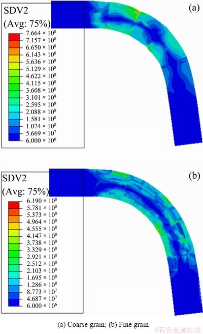
Fig. 10 Contour of SSDs

Fig. 11 Contour of GNDs
When a material undergoes plastic deformation, the dislocation density increases, leading to strain hardening. The larger the plastic deformation is, the higher the hardness of the material is after deformation. There is an equivalence relation between the total dislocation density and material hardness to some extent [38]. Consequently, Fig. 12 shows the distribution of total dislocation density, i.e., SSDs plus GNDs. It could be compared with the experimental hardness distribution in Fig. 9. For the coarse grain case, the total dislocation density distribution is anomalous which is similar to the hardness distribution by experiments. The maximum dislocation density dispersedly appears in the areas labeled A, B and C which are the borders between GBs and surfaces of foil. The high density areas, i.e., A, B and C are similar to the areas in the experiment, as shown in Fig. 9(a) and Fig. 12(a). For the fine grain case, an apparent lower density channel exists in the contour of total dislocation density distribution. This feature shows good agreement with the experiment of Fig. 9(b).
In conclusion, for the coarse grain case, the influence of individual grain is more significant. Mis-orientation of grains or the combination of hard orientation grains with soft orientation grains hinders appearance of middle soft channel. GBs across the thickness direction produce aggregation of GNDs, and GNDs serve as the wall to segment the potential channel. It is concluded that grains�� mis-orientation and GNDs store at the vicinity of GBs lead to the appearance of narrow inner layer and even the disappearance of soft channel. For the fine grain foil, the effect of individual grain is unremarkable due to more grains across the thickness, and all the grains near the neutral layer have relative small plastic deformation, resulting in the broader middle layer and obvious middle soft channel. Anyway, GNDs enhance the material hardness in both cases. It is concluded that the extra high hardness area in Fig. 9(a) may be the location of GBs, which induces evident deformation inhomogeneity.
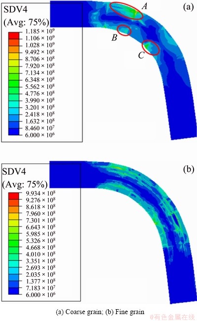
Fig. 12 Contour of sum of GNDs and SSDs
5 Conclusions
1) A non-local dislocation density based crystal plasticity model incorporated the GNDs dependent enhancing hardening is developed. The model views GNDs as the obstacles which hinder the movement of dislocation. The theory has the ability to capture the fundamental nature of the size dependent hardening behavior in the bent specimens.
2) The micro-bending of single crystalline foils with thicknesses ranging from 50 to 500 ��m shows the obvious ��smaller is stronger�� size effects. The simulation of the microstructural variables indicates that the accumulation of GNDs across the thickness dominates such size effects; however, SSDs almost has nothing to do with the thickness of specimens. Besides, it is concluded from the simulations that the strain gradient strengthening effects can be ignored when the thickness of specimens is larger than 500 ��m.
3) For the micro-bending of polycrystalline foils. The distribution of SSDs is mainly affected by grain orientation. Soft grain, which undergoes larger plastic deformation, has higher SSDs, and hard grain has lower SSDs. The distribution of GNDs is affected by grain size and grain orientation. For the coarse grain foil, i.e., only one or two grains across the thickness, GNDs not only enhance the hardness of material, but also impede the forming of middle soft channel or cut the potential soft channel. For fine grain foil, GNDs only strengthen the material hardness.
4) The differences of hardness contours obtained from experimental results are the combination effect of grain size, grain orientation and load inhomogeneity (strain gradient). The deformation inhomogeneity resulting from the microstructure is more severe than that from load (strain gradient) during polycrystalline micro-bending.
References
[1] XU Jie, WANG Chun-ju, SHAN De-bin, GUO Bin. Hybrid micro-forming processes and quality evaluation of micro-double gear [J]. Journal of Wuhan University of Technology: Mater Sci Ed, 2009, S1: 90-94.
[2] GEIGERA M, KLEINER M, ECKSTEIN R, TIESLER N, ENGEL U. Microforming [J]. CIRP Ann-Manuf Tech, 2001, 50(2): 445-462.
[3] ENGEL U, ECKSTEIN R. Microforming-from basic research to its realization [J]. J Mater Process Tech, 2002, 125: 35-44.
[4] WANG Chun-ju, SHAN De-bin, GUO Bin, ZHOU Jian, SUN Li-ning. Key problems in microforming processes of microparts [J]. J Mater Sci Tech, 2007, 23(2): 283-288.
[5] FU M W, YANG B, CHAN W L. Experimental and simulation studies of micro blanking and deep drawing compound process using copper sheet [J]. J Mater Process Tech, 2013, 213(1): 101-110.
[6] FU M W, CHAN W L. Geometry and grain size effects on the fracture behavior of sheet metal in micro-scale plastic deformation [J]. Mater Design, 2011, 32: 4738-4746.
[7] ENGEL U, ECKSTEIN R. Microforming-from basic research to its realization [J]. J Mater Process Tech, 2002, 125-126(9): 35-44.
[8] WANG Chun-ju, GUO Bin, SHAN De-bin, SUN Li-ning. Effects of specimen size on flow stress of micro rod specimen [J]. Transactions of Nonferrous Metals Society of China, 2009, 19: 511-515.
[9] WANG Chun-ju, GUO Bin, SHAN De-bin. Effect of die cavity dimension on micro U deep drawing behaviour with T2 foil [J]. Transactions of Nonferrous Metals Society of China, 2009, 19: 790-794.
[10] WANG Chun-ju, GUO Bin, SHAN De-bin. Polycrystalline model for FE-simulation of micro forming processes [J]. Trans Nonferrous Met Soc China, 2011, 21: 1362-1366.
[11] CHAN W L, FU M W, LU J. The size effect on micro deformation behaviour in micro-scale plastic deformation [J]. Mater Design, 2011, 32: 198-206.
[12] CHAN W L, FU M W. Experimental studies of plastic deformation behaviors in microheading process [J]. J Mater Process Tech, 2012, 212: 1501-1512.
[13] CHAN W L, FU M W. Studies of the interactive effect of specimen and grain sizes on the plastic deformation behavior in microforming [J]. Int J Adv Manuf Technol, 2012, 62: 989-1000.
[14] CHENG Ming, ZHANG Shi-hong. Investigation of micro formability of bulk amorphous alloy in the supercooled liquid state based on fluid flow and finite element analysis [J]. J Mater Sci Technol, 2009, 25(2): 277-280.
[15] STOLKEN J S, EVANS A G. A microbend test method for measuring the plasticity length scale [J]. Acta Mater, 1998, 46: 5109-5115.
[16] MCELHANEY K, VLASSAK J, NIX W. Determination of indenter tip geometry and indentation contact area for depth-sensing indentation experiments [J]. J Mater Research, 1998, 13: 1300-1306.
[17] FLECK N A, MULLER G M, ASHBY M F, Hutchinson J W. Strain gradient plasticity: Theory and experiments [J]. Acta Mater, 1994, 42: 475-487.
[18] HU Peng, PENG Lin-fa, LAI Xin-min, ZHANG Wei-gang. Instability analysis and experimental study of micro stamping process with thin sheet [J]. Journal of Shanghai Jiao Tong University, 2011, 45(1): 41-44. (inChinese)
[19] FLECK N A, HUTCHINSON J W. A phenomenological theory for strain gradient effects in plasticity [J]. J Mech Phys Solids, 1993, 41(12): 1825-1857.
[20] GAO H, HUANG Y, NIX W D, HUTCHINSON J W. Mechanism-based strain gradient plasticity��I. Theory [J]. J Mech Phys Solids, 1999, 47(6): 1239-1263.
[21] LI H Z, DONG X H, SHEN Y, DIEHL A, HAGENAH H, ENGEL U, MERKLEIN M. Size effect on springback behavior due to plastic strain gradient hardening in micro-bending process of pure aluminum foils [J]. Mater Sci Eng A, 2010, 527: 4497-4504.
[22] LI H Z, DONG X H, WANG Q, SHEN Y, DIEHL A, HAGENAH H, ENGEL U, MERKLEIN M. Determination of material intrinsic length and strain gradient hardening in micro-bending process [J]. Int J Solids Struct, 2011, 48: 163-174.
[23] GEERS M G D, BREKELMANS W A M, JANSSEN P J M. Size effects in miniaturized polycrystalline FCC samples: Strengthening versus weakening [J]. Int J Solids Struct, 2006, 43: 7304-7321.
[24] ASARO R J, RICE J R. Strain localization in ductile single crystals [J]. J Mech Phys Solids, 1977, 25: 309-338.
[25] HUANG Shi-yao, ZHANG Shao-rui, LI Da-yong, PENG Ying-hong. Simulation of texture evolution during plastic deformation of FCC, BCC and HCP structured crystals with crystal plasticity based finite element method [J]. Transactions of Nonferrous Metals Society of China, 2011, 21: 1817-1825.
[26] YANG M, DONG X H, ZHOU R, CAO J. Crystal plasticity-based forming limit prediction for FCC materials under non-proportional strain-path [J]. Mater Sci Eng A, 2010, 527: 6607-6613.
[27] ZHANG Hai-ming, DONG Xiang-huai, WANG Qian, ZENG Zhen. An effective semi-implicit integration scheme for rate dependent crystal plasticity using explicit finite element codes [J]. Comp Mater Sci, 2012, 54: 208-218.
[28] PARASIZ S A, VAN BENTHYSEN R, KINSEY B L. Deformation size effects due to specimen and grain size in micro-bending [J]. J Manuf Sci E�CT ASME, 2010, 132: 1-8.
[29] LI H Z, DONG X H, SHEN Y, ZHOU R, DIEHL A, HAGENAH H, ENGEL U, MERKLEIN M, CAO J. Analysis of microbending of CuZn37 brass foils based on strain gradient hardening models [J]. J Mater Process Tech, 2012, 212: 653-661.
[30] KOCKS U F, MECKING H. Physics and phenomenology of strain hardening: The FCC case [J]. Prog Mater Sci, 2002, 48: 171-273.
[31] CHEONG K S, BUSSO E P. Discrete dislocation density modelling of single phase FCC polycrystal aggregates [J]. Acta Mater, 2004, 52: 5665-5675.
[32] FRANCIOSI P. The concepts of latent hardening and strain hardening in metallic single crystals [J]. Acta Metall, 1985, 33: 1601-1612.
[33] ARSENLIS A, PARKS D M, BECKER R, BULATOV V. On the evolution of crystallographic dislocation density in non-homogeneously deforming crystals [J]. J Mech Phys Solids, 2002, 50: 1979�C2009.
[34] CERMELLIA P, GURTIN M E. On the characterization of geometrically necessary dislocations in finite plasticity [J]. J Mech Phys Solids, 2001, 49: 1539-1568.
[35] MA A, ROTERS F, RAABE D. A dislocation density based constitutive model for crystal plasticity FEM including geometrically necessary dislocations [J]. Acta Mater, 2006, 54: 2169-2179.
[36] BELYTSCHKO T, KRONGAUZ Y, ORGAN D, FLEMING M, KRYSL P. Meshless methods: An overview and recent developments [J]. Comp Meth Appl Mech Eng, 1996, 139: 3-48.
[37] MOTZ C, SCHOBERL T, PIPPAN R. Mechanical properties of micro-sized copper bending beams machined by the focused ion beam technique [J]. Acta Mater, 2005, 53: 4269-4279.
[38] GRACA S, COLACO R, CARVALHO P A, VILAR R. Determination of dislocation density from hardness measurements in metals [J]. Mater Letters, 2008, 62: 3812-3814.
�º���1�����滳1���� ٻ1 �������2
1. �Ϻ���ͨ��ѧ ģ��CAD���ҹ����о����ģ��Ϻ� 200030��
2. �ӱ����̴�ѧ ���繤��ѧԺ������ 056038
ժ Ҫ�����ÿ��ǷǾ����۽ṹ�ķǾֲ�λ���ܶȾ�����������Ԫģ�ͣ��о��������屡Ĥ�����������Ա��ε��ص㡣��ģ�Ͳ���ͳ�ƴ洢λ���ܶȺͼ��α���λ���ܶ���Ϊ���ڲ�״̬������ͨ�����α���λ���ܶȵ��ݻ���Ԥ�ⵥ���������Ĥ���������е�Ӧ���ݶ�ЧӦ�����ò�ͬ������С��CuZn37 ��-��ͭ�ྦྷ�屡Ĥ��������ʵ�飬�����������������κ��Ӳ�ȷֲ�ͼ����ģ��õ���λ���ܶȷֲ���ʵ���õ�Ӳ�ȷֲ����жԱȣ����ִ־�������ϸ������Ӳ�ȷֲ��IJ�ͬ��Ҫ����ͳ�ƴ洢λ���ܶȺͼ��α���λ���ܶ�����ġ������������������о��������ε��ص��λ���ܶȵ��ݻ���
�ؼ��ʣ��������ԣ�������ͳ�ƴ洢λ�������α���λ��
(Edited by Chao WANG)
Foundation item: Projects (50835002, 50821003, 50975174, 51275297) supported by the National Natural Science Foundation of China; Projects (200802480053, 20100073110044) supported by the PhD Programs Foundation of Ministry of Education of China
Corresponding author: Xiang-huai DONG; Tel/Fax: +86-21-62813435; E-mail: dongxh@sjtu.edu.cn
DOI: 10.1016/S1003-6326(13)62876-9

