电子束焊接析出硬化CuCrZr合金:模拟与实验
来源期刊:中国有色金属学报(英文版)2020年第8期
论文作者:Rajveer SINGH Sachin SINGH P. K. C. KANIGALPULA J. S. SAINI
文章页码:2156 - 2169
关键词:电子束焊接;焊道宽度;焊道熔透;模拟;铜铬锆合金
Key words:electron beam welding; bead width; bead penetration; modeling; copper-chromium-zirconium alloy
摘 要:为了在焊接析出硬化铜铬锆(PH-CuCrZr)合金时保持结构的一致性,采用电子束焊接(EBW)工艺。对PH-CuCrZr合金零件的EBW过程进行实验研究和数值模拟,建立三维有限元模型,以预测输出响应(焊道熔透和焊道宽度)与EBW输入参数(电子束电流、加速电压和焊接速度)之间的函数关系。采用一种具有高斯热分布的圆形、园锥形复合热源模拟EBW过程的深熔焊特性。在Ansys软件中开发用户自定义函数,进行数值模拟。将数值模拟结果与实验结果进行比较,两者吻合较好。所建模型可用于EBW过程中广泛涉及复杂几何形状问题的参数研究。输入电流是对焊道熔透和焊道宽度影响最大的输入参数,其贡献率分别为44.56%和81.13%。
Abstract: In order to maintain the structural consistency during the welding of precipitation hardened copper- chromium-zirconium (PH-CuCrZr) alloy components, electron beam welding (EBW) process was employed. Experimental study and numerical modeling of EBW process during welding of PH-CuCrZr alloy components were carried out. A 3D finite element model was developed to predict the output responses (bead penetration and bead width) as a function of EBW input parameters (beam current, acceleration voltage and weld speed). A combined circular and conical source with Gaussian heat distribution was used to model the deep penetration characteristic of the EBW process. Numerical modeling was carried out by developing user defined function in Ansys software. Numerical predictions were compared with the experimental results which had a good agreement with each other. The developed model can be used for parametric study in wide range of problems involving complex geometries which are to be welded using EBW process. The present work illustrates that the input current with a contribution of 44.56% and 81.13% is the most significant input parameter for the bead penetration and bead width, respectively.
Trans. Nonferrous Met. Soc. China 30(2020) 2156-2169
Rajveer SINGH, Sachin SINGH, P. K. C. KANIGALPULA, J. S. SAINI
Department of Mechanical Engineering, Thapar Institute of Engineering and Technology, Patiala-147004, Punjab, India
Received 12 November 2019; accepted 11 July 2020
Abstract: In order to maintain the structural consistency during the welding of precipitation hardened copper- chromium-zirconium (PH-CuCrZr) alloy components, electron beam welding (EBW) process was employed. Experimental study and numerical modeling of EBW process during welding of PH-CuCrZr alloy components were carried out. A 3D finite element model was developed to predict the output responses (bead penetration and bead width) as a function of EBW input parameters (beam current, acceleration voltage and weld speed). A combined circular and conical source with Gaussian heat distribution was used to model the deep penetration characteristic of the EBW process. Numerical modeling was carried out by developing user defined function in Ansys software. Numerical predictions were compared with the experimental results which had a good agreement with each other. The developed model can be used for parametric study in wide range of problems involving complex geometries which are to be welded using EBW process. The present work illustrates that the input current with a contribution of 44.56% and 81.13% is the most significant input parameter for the bead penetration and bead width, respectively.
Key words: electron beam welding; bead width; bead penetration; modeling; copper-chromium-zirconium alloy
1 Introduction
Precipitation hardened copper chromium zirconium (PH-CuCrZr) alloy belongs to the group of copper alloy that has very high strength and thermal conductivity. This alloy possesses high conductivity because of very low solubility of Cr and Zr in copper while the outstanding strength is characteristic to precipitation and particle- dispersion strengthening mechanisms [1]. PH-CuCrZr is the key material used in the manufacturing of heat sink components that are subjected to high heat flux. Some of the examples include swirl tubes, toroidal pump limiter, cooling tubes of the diverter which are employed in the international thermal experimental reactor (ITER) applications [2]. It is reported that the mechanical and electrical properties of welded PH-CuCrZr alloy decrease due to the weld stress and weld defects produced by the traditional welding process with a considerable difference of microstructure between the welded joint and the base material [3,4].
Electron beam welding (EBW) is a highly dependable process, which is best suited for close tolerance parts with challenging requirements of various industrial applications. EBW is mainly used in welding of refractory, reactive and dissimilar materials. The characteristics, such as high depth-to-width ratio (as high as 40:1), high purity and reliability of the joints make EBW a useful joining process in nuclear, aerospace and automotive sectors. It is a fusion welding process, in which a highly focused electron beam (spot diameter of a few microns to a few millimeters), is utilized as an intense heat source for joining two metals. When the electron beam strikes the surface, its kinetic energy is transferred into the work material generating extreme heat in a short duration of time and thus, resulting into a very fine and deep weld with insignificant heat affected zone [5]. As per the available literature [6,7], it is found that the formation of keyhole shape weld bead takes place during the EBW process. It is due to the local heating and locally vaporizing of the molten material by the high-energy density of the electron beam. As for the formation of keyhole, high energy passes through the thickness rather than the width of the part. This helps for producing CuCrZr alloy weldments with a less change in microstructure and small heat affected zone (HAZ) which lowers the residual stress and distortion generated after the EBW process.
Figure 1 shows the axisymmetric triode type gun and column assembly. The triode gun design consists of high voltage power supply connections, cathode (filament), grid cup (wehnelt cup), anode and vacuum pumping system. The other subassembly components consist of high voltage cable, focusing and deflection coils. During the EBW process, electrons are emitted by thermal emission from a tungsten or tantalum cathode and accelerated by an electrostatic field in the direction of the anode. Electron beam comprises of charge carriers (electrons) accelerated by a potential difference in the range of tens of kilovolts.

Fig. 1 Schematic diagram of electron beam welding setup
Literature shows that a considerable amount of experimental, analytical and numerical work is done on EBW process by different researchers. TOSHIYUKI and GIEDT [6] proposed a cylindrical heat source with an elliptical cross section to model the electron beam of the EBW process. Authors [7,8] developed a 3D thermo-mechanical model to predict temperature, distortion and residual stresses during the EBW of Inconel. Similar experimental and numerical analysis of the EBW process was carried out by CHIUMENTI et al [9] using Ti64 as the work material. It was shown that the distortion and generated residual stresses were minimum due to the focused heat input during the EBW process. RAI et al [10] modeled the temperature and fusion zone geometry with respect to time during the EBW of Ti64 alloy. LUO et al [11] carried out the simulation and experimental study on the magnesium alloy. It was concluded that the heat input significantly affects the weld shape. 2D thermo-mechanical modeling of the EBW process during the welding of two different alloys of steel was carried out by CARIN et al [5]. ZHANG et al [12] performed the EBW simulation study during the joining of steel alloy and titanium alloy sheet. The electron beam shape was modeled as a rotated parabola with temperature and residual stresses as the outputs of the simulation. RAJABI and GHOREISHI [13] carried out the numerical study to investigate the effect of the workpiece thickness on the residual stresses. It was found that the more the thickness was, the larger the residual stresses were in the workpiece. BONAKDAR et al [14] performed the numerical modeling of the EBW process to investigate the residual stresses and distortion developed in the fusion zone (FZ) and HAZ of the Inconel weldments. Modeling of residual stresses and distortion was also carried out by LACKI and ADAMUS [15] during the pulsed electron beam welded pipes with different thicknesses. To reduce the computational cost during the EBW of large Al alloy sheets, parallel computation techniques were explored by TIAN et al [16]. It was found that the welding speed and power had a direct influence on the temperature generated during the EBW process. LIU and HE [17] developed a 2D mathematical model to study the fluid flow and heat transfer during the EBW process. TRUSHNIKOV and PERMYAKOV [18] also modeled the effect of electron beam oscillation on the shape of the weld zone. JAYPURIA et al [19] modeled the electron beam as a conical heat source and predicted the residual stress in the PH-CuCrZr alloy plates after the EBW process.
As found from the literature review [6-18], most of the work related to the numerical and experimental studies of the EBW process has been done on stainless steel, Inconel, magnesium and titanium alloys. However, very limited work has been carried out during the EBW of PH-CuCrZr alloy. Detailed experimental study needs to be carried out to investigate the individual as well as the combined effect of EBW input parameters on the output responses. The present work contributes to the development of a 3D thermal model in combination with a heat source for simulating the EBW process during the welding of PH-CuCrZr alloy plates. The work illustrates the formulation carried out for numerical simulation of the EBW process which was validated using the experimental results in terms of weld geometry, i.e., bead width and bead penetration.
2 Finite element formulation of electron beam welding process
The following section discusses the governing equations for the thermal analysis of electron beam welding process, discretization and boundary conditions for the finite element analysis of the process.
2.1 Governing equation and heat source model
The 3D governing equation for transient thermal analysis in cartesian coordinate system is given as [20]
 (1)
(1)
where ρ denotes the density of the material, C denotes the specific heat capacity, k is the thermal conductivity, T is the transient temperature, Q represents the heat generation rate per unit volume and v is the velocity of electron beam. Width, length and depth of the workpiece are considered along x, y and z directions, respectively. It was assumed that the electron beam moves along the positive x direction of the coordinate system.
The workpiece material in the present analysis is assumed as isotropic and homogenous. The key component in carrying the finite element analysis of the EBW process is the modeling of the electron beam. As found from the literature [7,8], EBW process is capable of forming deep welds due to its keyhole characteristics. Due to the keyhole shape of the weld, a compound heat source model was developed in the present work by combining circular and conical heat source models by means of moving local coordinate system. EBW process is a highly efficient process with minimum energy loss during the welding. In the present work, it is assumed that 90% of the generated electron beam energy is absorbed by the workpiece material. Out of 90% of the power, 20% is considered to be absorbed on the workpiece surface (Qs), while 70% of the power (Qk) is responsible for the formation of keyhole. Figure 2 shows the circular heat source with Gaussian distribution of heat flux which is applied on the workpiece surface (x and y directions). To simulate the formation of a keyhole, a conical heat source is modeled along the thickness, i.e., z direction, of the workpiece.
For circular heat source, Gaussian heat flux distribution at any point on the workpiece surface, Q (x, y), can be given by
 (2)
(2)
The heat flux distribution, Q (x, y, z) simulating the generation of keyhole is given by
 (3)
(3)
The total heat flux absorbed by the workpiece is given by
Q0=ηVI (4)
where η is the efficiency of the electron beam welding machine, V is voltage supplied (kV), I is current supplied (mA), Q is heat flux (W/mm2), H is thickness of the work piece (m) and r0 is radius of electron beam (m).
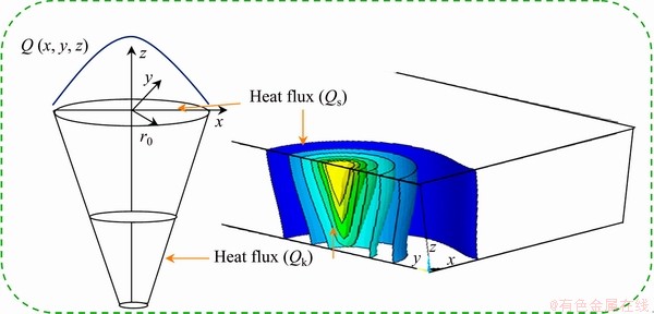
Fig. 2 Schematic diagram of compound heat source model with corresponding numerically modeled heat source showing Gaussian and conical heat flux
2.2 Geometric modeling
Bead-on-plate (BOP) welding simulations are performed on 100 mm × 65 mm × 10 mm sheet of PH Cu-0.83Cr-0.06Zr alloy using the EBW process (Fig. 3). During the simulation, considering the symmetry of the plate and the heat source, a 3D symmetric finite element (FE) model (A-I-K-C- F-N-L-D) for transient thermal analysis is employed. To simulate, electron beam is moved along the interface A-B-C-D-E-F as shown in Fig. 3.
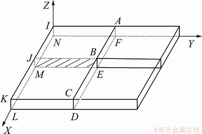
Fig. 3 Schematic representation of typical BOP geometry
Developed model is discretized using solid eight-noded brick elements for the thermal analysis with a single degree of freedom, i.e., temperature at each node. In order to capture the thermal results accurately in the weldment region and simultaneously to save the computational expenses, a fine mesh is generated in the weldment region while a coarse mesh is chosen for far-off regions, as shown in Fig. 4. The convergence study was done and the model was finally discretized using 211191 nodes and 200104 elements.

Fig. 4 Finite element mesh generation of domain
2.3 Material properties
Temperature gradient around the welding zone leads to a considerable change in the material properties. Therefore, temperature dependent material properties are incorporated to enhance the accuracy of the developed thermal model. However, PH-CuCrZr alloy does not have an entire database for modeling in the commercial area. The present study used data (Fig. 5) [21] which gave the properties upto the temperature of 773 K. These properties were assumed as constant above the temperature of 773 K. Melting and vaporization temperatures of PH-CuCrZr alloy are considered as 1356 and 2850 K, respectively, during the simulation to determine the weld pool geometry and keyhole boundary [22].

Fig. 5 Variation of PH-CuCrZr alloy properties with temperature [21]
2.4 Boundary conditions
Essential boundary conditions are applied at the start of the EBW process. At time, t=0, the workpiece has a uniform ambient temperature of 300 K (27 °C). Heat supplied by the electron beam to the workpiece is conducted to the workpiece edges. Major amount of heat loss in the form of radiation occurs during the EBW process due to the large temperature difference between the workpiece and the environment. Therefore, the boundary conditions defined on the surface of the workpiece are given as
 (5)
(5)
where kn is the thermal conductivity of the material normal to the surface of the workpiece, n is the normal vector to the surface, ω is emissivity, θ is the Stefan-Boltzmann constant which is taken as 1.7×10⁻⁵ W/(m2・K4) and T0 is the ambient temperature. The first and second terms in Eq. (5) depict the heat loss due to conduction and radiation, respectively.
3 Simulation of moving heat source
Heat flux is calculated as a function of laser power, beam dimensions and the fraction of energy absorbed by workpiece material, given by Eqs. (2) and (3). Heat flux is incorporated in the simulation by the user defined function (UDF) written in Ansys programming design language (APDL). The weld path that is to be followed during the welding simulation is also defined through UDF. Figure 6 shows the applied heat flux on a 3D model. Heat flux distribution at a particular load step is calculated by developing a local cylindrical coordinate system at the center of the electron beam, whereas the heat source model is moved with the help of global cartesian coordinate system. The radius of the local coordinate system is equal to the initial beam radius. The weld path consists of applying heat source at various load steps for a particular time step size which is calculated using Eqs. (6) and (7):
 (6)
(6)
 (7)
(7)
where NLS is the number of load steps, LT is the total length of the weld path, SL is step length, TSS is the time step size and WS is the weld speed.

Fig. 6 Model with various load steps along weld path
Initially, heat flux is applied at nodes for a particular load step at time, tn. At time, tn+1 heat source is moved by a step length which is the subsequent load step along the weld path and heat flux is recalculated for various nodes by deleting the heat flux of the previous load step. This process is repeated until the electron beam reaches the end of the workpiece, thus simulating the moving electron beam during the EBW process. The relation between tn and tn+1 is given by
tn+1=tn+TSS (8)
3.1 Thermal analysis of PH-CuCrZr alloy (spot welding)
Initially, for carrying out the numerical study, a code is developed to simulate the spot welding of PH-CuCrZr alloy using the EBW process. To accurately capture the shape and size of weld bead (bead penetration and bead width) at various EBW input parameters, circular and conical heat source models with Gaussian distribution of heat flux are used in the simulation. The complete spot welding simulation consists of two steps: first, to apply the heat source model and second to remove the applied heat source model to cool the weld bead by allowing the heat loss due to conduction and radiation. There is no heat loss due to convection as EBW setup is enclosed in a vacuum chamber. Figure 7 shows the temperature profile at current of 70 mA and voltage of 50 kV applied for 1 s.
3.2 Thermal analysis of PH-CuCrZr alloy (moving heat source)
After developing the numerical model of the EBW process for spot welding, the model is further enhanced to simulate the moving electron beam during the EBW process. Heat source model is applied in the form of multiple load steps (Eq. (6)) along the weld direction for a given time step size (Eq. (7)) calculated from the weld speed. Figure 8 shows the temperature contours for a moving heat source with a welding speed of 600 mm/min, beam current of 110 mA and the beam voltage of 50 kV. As the heat source is moved along length of the workpiece, it causes changes in the temperature distribution with the highest temperature at the center of the electron beam.

Fig. 7 Temperature profiles during spot EBW process at current of 70 mA and voltage of 50 kV
4 Experimental
Experimental work for studying the effect of EBW input parameters on bead geometry (bead width and bead depth) for bead-on-plate welded CuCrZr alloy plate with dimensions of 100 mm × 65 mm × 10 mm (Fig. 9(a)) is carried out on EBW facility available at Bhabha Atomic Research Centre (BARC), Mumbai, Maharastra, India. The pressures of 9.2 mPa and 0.68 mPa are maintained in the work chamber and gun chamber of the EBW machine, respectively. The setup has a capacity of 80 kV, 24 kW and is shown in Fig. 9(b).
Parametric study of the EBW process is carried out by using the central composite design (CCD) method. The aim of conducting parametric analysis is to study the effect of EBW input parameters, viz., beam current (I), accelerating voltages (V), the weld speed (S) and their interaction on EBW output responses, viz., BW and BP. Table 1 shows the actual values of the various EBW input parameters used for carrying the numerical study. Range of these parameters is selected by conducting initial trial experiments. A total of 23+2×3+3=17 combination of process parameters was taken into account for these experiments.

Fig. 8 Temperature distribution for moving heat source at different time
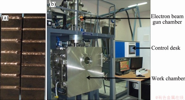
Fig. 9 PH-CuCrZr alloy specimens with bead-on-plate welding (a) and electron beam welding machine (b)
Table 1 Process parameters and their ranges used for EBW process

5 Results and discussion
In the following section, results of the experimental and numerical modeling of the EBW process during the welding of PH-CuCrZr alloy plates are reported. The effect of EBW process input parameters, i.e., beam current, voltage and welding speed on the experimental and simulated values of the bead width and bead depth are discussed.
5.1 Validation of developed numerical thermal model
Thermal model developed in the present work is compared with the experimental results in terms of weld bead geometry, i.e., bead width and bead depth. Table 2 illustrates the comparative study between the numerically and experimentally predicted results. In Table 2, BPE and BWE are the experimental values of bead penetration and bead width, while BPS and BWS are their corresponding numerically predicted values. As can be seen from Table 2, the experimental and simulated results are in fairly good agreement with each other.
Figure 10 shows the comparison of experimental and numerical results. The right sides of Figs. 10(a) and (b) are optical micrographs of the experimentally welded plate using the EBW process while the left sides of Figs. 10(a) and (b) show the cross sections of numerically simulated temperature profile. EBW process passes high energy through the thickness rather than the width of the plate, resulting in a narrow and deep cavity called ‘keyhole’ as shown by the contour in Fig. 10, at the vaporization temperature of 2850 K for PH-CuCrZr alloy. Keyhole is shown as “V” shape of the weld bead predicted by simulation, with the same shape obtained by the experimental results. Numerically predicted values of BW and BP are shown by the transverse and longitudinal extension of the red zone in the temperature contours. As shown in Fig. 10(a), errors between the experimental and simulated results of BW, BP are 16.67% and 5.17%, respectively. While in Fig. 10(b) there is an error of 18.92% for BW and an error of 2.34% for BP, respectively. Thus, experimental and simulated results are in fairly good agreement with each other.
Table 2 Detailed plan of experiments with corresponding output responses

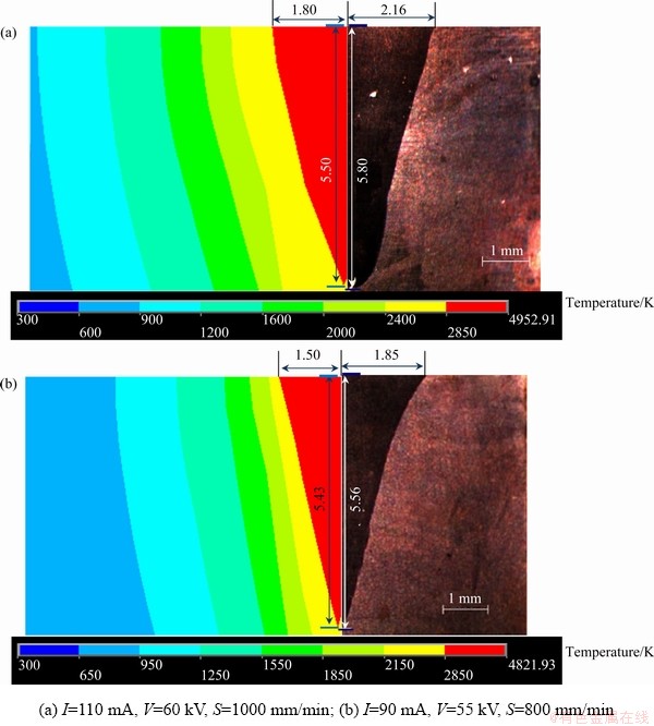
Fig. 10 Comparision between experimentally and simulated values of bead width and bead penetration at various EBW input parameters
5.2 Analysis of variance
To study the contributions of individual EBW input parameters as well as their interactions on the EBW output responses, ANOVA analysis was carried out. Tables 3 and 4 show the results of ANOVA analysis carried out on bead width and bead penetration for experimental and numerical results, respectively. As shown in Table 3, the model-values of 0.01 and 0.00 for simulated and experimental results for bead width, i.e., BWs and BWE, respectively, being less than 0.05 (significance level, α for 95% confidence interval) imply that both models are significant. It can be seen that the linear order term, I, have the highest contribution for BW. Simulated results show that the linear order terms S and IS are also significant but are not much reflected in the experimental results.
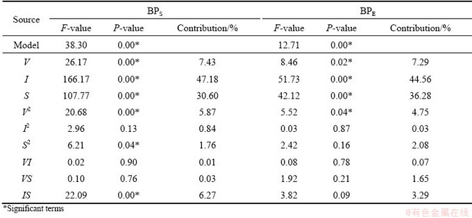
As can be seen from Table 4, all EBW input parameters play a significant role in deciding bead penetration. Numerical study predicts 47.18%, 30.60%, 7.43% and 5.87% contribution of I, S, V and V 2, respectively. Similar trend is observed for the experimental results with 44.56%, 36.28%, 7.29% and 4.75% contribution of I, S, V and V 2, respectively.
Regression equations for the experimentally obtained bead width, BWE, and simulated bead width, BWS, are given by Eqs. (9) and (10):
BWE=8.99-0.274V+0.1161I-0.01169S+0.00167V 2-
0.000020I2+0.000003S2-0.000713VI+
0.000206VS-0.000054IS (9)
Table 3 Analysis of variance for BWS and BWE
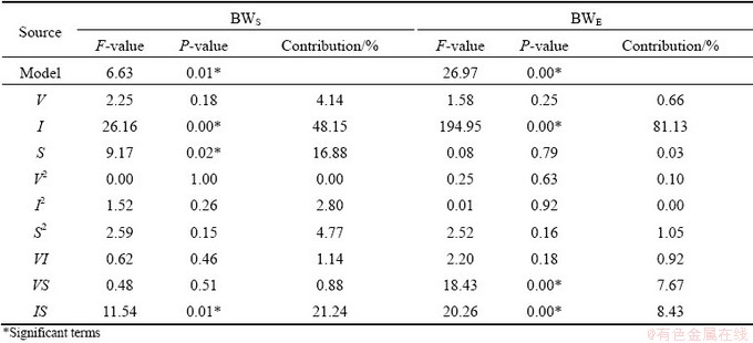
Table 4 Analysis of variance for BPS and BPE
BWS=2.6+0.043V+0.041I-0.00935S+0.00003V2+
0.000577I2+0.000008S2-0.00085VI+
0.000075VS-0.000092IS (10)
Similarly, regression equations for the experimentally obtained bead depth, BPE, and simulated bead depth, BPS, are given by Eqs. (11) and (12):
BPE=-88.2+3.66V+0.090I-0.0363S-0.0349V2+
0.000157I2+0.000014S2+0.00063VI+
0.000298VS-0.000105IS (11)
BPS=-117.3+4.503V+0.032I-0.0167S-0.04005V2+
0.000947I2+0.000014S2-0.00016VI+
0.000041VS-0.000150IS (12)
5.3 Effect of beam current
Figure 11 shows the variation of bead width and bead penetration with beam current. Bead width and bead penetration increase with the increase in beam current due to the fact that a higher current leads to an increase in the number of the electrons that are impinging the workpiece surface which results in high space charge inside the weld pool which further leads to an increase in EBW output responses. At a higher current, the phenomenon known as space charge effect takes place. In this process, repulsion between individual electrons takes place which increases the focal diameter of the electron beam and hence the bead width increases at a higher beam current [23]. Therefore, beam current is the most significant input parameter that affects the bead width. Similar results were shown by the ANOVA analysis. Figure 12 shows the optical images depicting the bead width and bead penetration for BOP welding at different currents. Bead width increases from 3.06 to 4.08 mm with an increase of current from 70 to 110 mA. For the same range of current, the increase in bead penetration is from 4.60 to 6.33 mm.
5.4 Effect of weld speed
As shown in Figs. 13(a) and (b), both simulated and experimental values of bead width and bead penetration decrease with an increase in weld speed. This is due to the fact that as the weld speed increases, heat input per unit volume will decrease, which leads to a decrease in bead width and bead penetration. It was found from the ANOVA analysis of experimental results that the contribution of linear terms of weld speed (S) in determining the bead depth is 36.28% which decreases to 0.03% in the case of bead width. Simulated results show the same trend as the experimental ones. Thus, the effect of weld speed is very dominant in determining the bead depth as compared to bead width.

Fig. 11 Effect of beam current on bead width (a) and bead penetration (b) (V=55 kV, S=800 mm/min)

Fig. 12 Optical images of weld bead during electron beam welding of PH-CuCrZr alloy plates at different currents

Fig. 13 Effect of weld speed on bead width (a) and bead penetration (b) (V=55 kV, I=90 mA)
5.5 Effect of accelerating voltage
Kinetic energy of the beam electrons is directly proportional to the accelerating voltage. As the voltage increases, kinetic energy of the electrons will increase, which results in an increase of bead width and bead penetration (Fig. 14). However, the contributions of voltage (V) in determining BPS and BPE are 7.43% and 7.29%, respectively. While, 4.14% and 0.66% are the contributions of voltage in deciding BWS and BWE, respectively. Therefore, the transfer of kinetic energy of the electrons takes place more in depth as compared to the width of the welded plate.
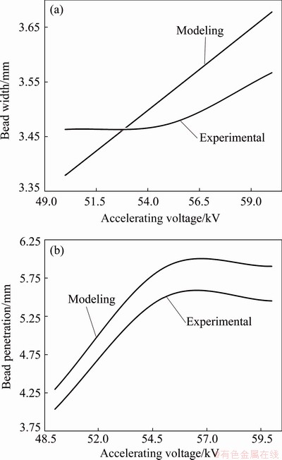
Fig. 14 Effect of accelerating voltage on bead width (a) and bead penetration (b) (S=800 mm/min, I=90 mA)
The images of bead geometry at different accelerating voltages are shown in Fig. 15. It can be seen from the images that the effect of accelerating voltage is more dominant on bead penetration as compared to its effect in influencing the bead width.

Fig. 15 Optical images of weld bead during electron beam welding of PH-CuCrZr alloy plates at different accelerating voltages
6 Conclusions
(1) As found from the simulation study, contributions of current (I and I2), weld speed (S and S2) and accelerating voltage (V and V2) are 48.02%, 32.36% and 13.3%, respectively in determining the bead penetration. While, 44.59%, 38.36% and 12.04% are the experimentally determined contribution of current, weld speed and voltage, respectively.
(2) Current is the most significant input process parameter that affects the bead width. Its contribution is as high as 81.13% as calculated from the experimental results.
(3) Bead width and bead penetration increase with the increase in beam current and accelerating voltage. While, welding speed adversely affects the bead penetration and bead width.
References
[1] ROTTI C, CHAKRABORTY A K, AHMED I, ROOPESH G, BANDYOPADHYAY M, SINGH M J, SHAH S, PHUKAN A, YADAV R K, PANDA N, BALASUBRAMANIAN K. Development of CuCrZr alloy for applications in neutral beams [C]//IEEE 24th Symposium on Fusion Engineering. Chicago, IL, USA: IEEE, 2011: 1-5.
[2] KANIGALPULA P K C, PRATIHAR D K, JHA M N, DEROSE J, BAPAT A V, PAL A R. Experimental investigations, input-output modeling and optimization for electron beam welding of Cu-Cr-Zr alloy plates [J]. Int J Adv Manuf Technol, 2016, 85: 711-726.
[3] FENG H, JIANG H, YAN D, RONG L. Microstructure and mechanical properties of a CuCrZr welding joint after continuous extrusion [J]. J Mater Sci Technol, 2015, 31: 210-216.
[4] YUNLIAN Q, JU D, QUAN H, LIYING Z. Electron beam welding, laser beam welding and gas tungsten arc welding of titanium sheet [J]. Mater Sci Eng A, 2000, 280: 177-181.
[5] CARIN M, ROGEON P, MANACH P Y, PILVIN P, MENES O, SIGRIST J F. Thermo-mechanical modelling for the opening of electron-beam welded joints [C]//Am Soc Mech Eng Press Vessel Pip Div PVP. Vancouver, British Columbia, Canada, 2006: 73-79.
[6] TOSHIYUKI M, GIEDT W H. Heat transfer from an elliptical cylinder moving through an infinite plate applied to electron beam welding [J]. Int J Heat Mass Transf, 1982, 25: 807-814.
[7] FERRO P, ZAMBON A, BONOLLO F. Investigation of electron-beam welding in wrought Inconel 706― Experimental and numerical analysis [J]. Mater Sci Eng A, 2005, 392: 94-105.
[8] LUNDBACK A, RUNNEMALM H. Validation of three- dimensional finite element model for electron beam welding of Inconel 718 [J]. Sci Technol Weld Join, 2005, 10: 717-724.
[9] CHIUMENTI M, CERVERA M, DIALAMI N, WU B, JINWEI L, de SARACIBAR C A. Numerical modeling of the electron beam welding and its experimental validation [J]. Finite Elem Anal Des, 2016, 121: 118-133.
[10] RAI R, BURGARDT P, MILEWSKI J O, LIENERT T J, DEBROY T. Heat transfer and fluid flow during electron beam welding of 21Cr-6Ni-9Mn steel and Ti-6Al-4V alloy [J]. J Phys D: Appl Phys, 2009, 42: 025503.
[11] LUO Y, YOU G, YE H, LIU J. Simulation on welding thermal effect of AZ61 magnesium alloy based on three- dimensional modeling of vacuum electron beam welding heat source [J]. Vacuum, 2010, 84: 890-895.
[12] ZHANG B G, WANG T, DUAN X H, CHEN G Q, FENG J C. Temperature and stress fields in electron beam welded Ti-15-3 alloy to 304 stainless steel joint with copper interlayer sheet [J]. Trans Nonferrous Met Soc China, 2012, 22: 398-403.
[13] RAJABI L, GHOREISHI M. Heat source modeling and study on the effect of thickness on residual stress distribution in electron beam welding [J]. J Weld Join, 2017, 35: 49-54.
[14] BONAKDAR A, MOLAVI-ZARANDI M, CHAMANFAR A, JAHAZI M, FIROOZRAI A, MORIN E. Finite element modeling of the electron beam welding of Inconel-713LC gas turbine blades [J]. J Manuf Process, 2017, 26: 339-354.
[15] LACKI P, ADAMUS K. Numerical simulation of the electron beam welding process [J]. Comput Struct, 2011, 89: 977-985.
[16] TIAN Y, WANG C, ZHU D, ZHOU Y. Finite element modeling of electron beam welding of a large complex Al alloy structure by parallel computations [J]. J Mater Process Technol, 2008, 199: 41-48.
[17] LIU C C, HE J S. Numerical analysis of thermal fluid transport behavior during electron beam welding of 2219 aluminum alloy plate [J]. Trans Nonferrous Met Soc China, 2017, 27: 1319-1326.
[18] TRUSHNIKOV D N, PERMYAKOV G L. Numerical simulation of electron beam welding with beam oscillations [C]//IOP Conf Ser: Mater Sci Eng. Bristol, UK: IOP Publishing Ltd., 2017: 012085.
[19] JAYPURIA S, SHEOKAND V, KUMAR D, JHA M N. Finite element analysis to determine residual stress in electron beam welding of CuCrZr alloy plates and experimental validation [J]. Materialstoday: Proceedings, 2018, 5: 19321-19329.
[20] VEMANABOINA H, AKELLA S, BUDDU R K. Welding process simulation model for temperature and residual stress analysis [J]. Procedia Mater Sci, 2014, 6: 1539-1546.
[21] PINTSUK G, BLUMM J, HOHENAUER W, HULA R C, KOPPITZ T, LINDIG S, PITZER D, ROHDE M, SCHODERBOCK P, SCHUBERT T, TIETZ F. Interlaboratory test on thermophysical properties of the ITER grade heat sink material copper-chromium-zirconium [J]. Int J Thermophys, 2010, 31: 2147-2158.
[22] LI M, ZINKLE S J. Physical and mechanical properties of copper and copper alloys [J]. Compr Nucl Mater, 2012, 4: 667-690.
[23] JHA M N, PRATIHAR D K, BAPAT A V, DEY V, ALI M, BAGCHI A C. Knowledge-based systems using neural networks for electron beam welding process of reactive material (Zircaloy-4) [J]. J Intell Manuf, 2014, 25: 1315-1333.
Rajveer SINGH, Sachin SINGH, P. K. C. KANIGALPULA, J. S. SAINI
Department of Mechanical Engineering, Thapar Institute of Engineering and Technology, Patiala-147004, Punjab, India
摘 要:为了在焊接析出硬化铜铬锆(PH-CuCrZr)合金时保持结构的一致性,采用电子束焊接(EBW)工艺。对PH-CuCrZr合金零件的EBW过程进行实验研究和数值模拟,建立三维有限元模型,以预测输出响应(焊道熔透和焊道宽度)与EBW输入参数(电子束电流、加速电压和焊接速度)之间的函数关系。采用一种具有高斯热分布的圆形、园锥形复合热源模拟EBW过程的深熔焊特性。在Ansys软件中开发用户自定义函数,进行数值模拟。将数值模拟结果与实验结果进行比较,两者吻合较好。所建模型可用于EBW过程中广泛涉及复杂几何形状问题的参数研究。输入电流是对焊道熔透和焊道宽度影响最大的输入参数,其贡献率分别为44.56%和81.13%。
关键词:电子束焊接;焊道宽度;焊道熔透;模拟;铜铬锆合金
(Edited by Xiang-qun LI)
Corresponding author: Sachin SINGH; E-mail: sachin.singh@thapar.edu
DOI: 10.1016/S1003-6326(20)65368-7

