Article ID: 1003-6326(2005)02-0452-05
FE simulation and process analysis on forming of aluminum alloy multi-layer cylinder parts with flow control forming
WANG Xin-yun(������), WU You-sheng(������),
XIA Ju-chen(�ľ���), HU Guo-an(������)
(State Key Laboratory of Die and Mould Technology, Huazhong University of Science and Technology, Wuhan 430074, China)
Abstract: The aluminum alloy parts used in airbag of car were studied with flow control forming(FCF) method, which was a good way to low forming force and better mechanical properties. The key technology of FCF was the design of control chamber to divide metal flow. So, the design method of FCF was analyzed and two type of control chamber were put forward. According to divisional principle, calculation model of forming force and approximate formula were given. Then forming process of aluminum alloy multi-layer cylinder parts was simulated. The effect of friction factor, die radius and punch velocity on metal flow and forming force was obtained. Finally, the experiment was preformed under the direction of theory and finite element(FE) simulation results. And the qualified parts were manufactured. The simulation data and experimental results show that the forming sequence of inner wall and outer wall, and then the force step, can be controlled by adjusting the process parameters. And the FCF technology proposed has very important application value in precision forging.
Key words: flow control forming; multi-layer cylinder; process analysis; force calculation CLC number: TG136
Document code: A
1 INTRODUCTION
Nowadays, especially in auto industry, how to reduce the energy consuming is a hot topic. The basic ways to realize it include adopting light mass materials(aluminum alloy, magnesium alloy, etc), redesigning parts construction and using new precision forming method[1-6]. By means of precision forming method, light mass parts can be manufactured and used widely in auto industry and other fields[7-15]. Recently, a new forming method called as flow control forming(FCF) is introduced to manufacture complex parts[16]. With FCF method, the flow of metal material can be controlled, so the precision forming of those very complex parts can be realized. Accordingly, the defects such as folder and under-filling can be avoided, and the mechanical properties can be improved.
Aluminum alloy multi-layer cylinder parts, such as gland bush, shell and capacitor parts, are used widely in auto and other civilian industry fields today(see Fig.1). Among these, the gland bush and shell is the key part of car��s airbag. Due to the used purity aluminum material has good plastic and lower deformation resistance, the multi-layer capacitor has realized the mass production with cold extrusion method in 1970s. The gland bush and shell usually used with high strength aluminum alloy material, however, are not easy to be manufactured with plastic working method. The reason is that the used aluminum alloy has bad plasticity and high strength, very complex shape, and the severe requirement to mechanical properties like ��b. So, before new technology is developed, the conventional methods such as pressure casting or cutting methods are adopted to make these kinds of parts. In this paper, the FCF technology will be adopted to make multi-layer cylinder parts. Process analysis and the calculation of force during the experimental process of aluminum alloy multi-layer cylinder will be studied, and then the specimen will be manufactured.
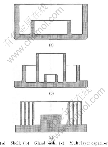
Fig.1 Multi-layer cylinder parts
2 TECHNOLOGY ANALYSES AND CONTROL CHAMBER DESIGN
2.1 Technology analysis of FCF
There are two key points during FCF process, the one is to control the metal flow direction and the position, the other is to control the forming force to obtain longer equipment and die life. The key technology of FCF is the design of control chamber to divide metal flow. According to the shape characteristics of multi-lay cylinder parts, the parts can be formed with forward close die forging or backward close die forging (see Fig.2).

Fig.2 Backward close die forging
2.2 Design of transverse direction ring shape control chamber
The approximate relationship between the height of ring shape control chamber hc and the radius of flange of die chamber r0(=d0/2) can be expressed as Eqn.(1). The outer radius of ring shape control chamber rc can be valued as Eqn.(2), and accordingly, the volume of control chamber Vk can be obtained by Eqn.(3)[7]:
hc=0.082r0(1)
rc=(1.1-1.15)r0(2)
Vk=0.06r30(3)
2.3 Design of longitudinal direction ring shape control chamber
As to multi-layer cylinder parts, Eqn.(4) was proposed to estimate which layer cylinder wall of the part will be formed at last. Eqn.(4) shows that that filling sequence can be determined according to the value of height-thickness ratio, friction factor and radius of cylinder wall root. Obviously, when all the cylinder walls have the same friction condition and radius value, then Eqn.(5) was obtained. The cylinder wall that has the highest value of height-thickness ratio is the cylinder wall that formed last:
Ki=f(mi, ri)hi/ti(4)
ki=hi/ti(5)
where ki (or Ki) is the height-thickness ratio, hi is the height of cylinder wall, and ti is the thickness of cylinder wall(i=1, 2, ��, n).
The dimension of control chamber can be obtained by Eqns.(6) and (7):
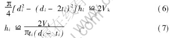
where di is the outer radius of cylinder wall.
2.4 Calculation of forming force
If the scheme shown in Fig.2(a) is adopted, the forming force can be calculated according to Ref.[7]. In this paper, the forming force is studied when the scheme of longitudinal direction cylinder control chamber is adopted (see Fig.2(b)). The calculation model of forming force of gland bush part (see Fig.1(a)) is shown in Fig.3.
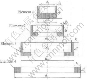
Fig.3 Calculation model of close die forging force
So, the total forming force can be expressed as
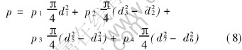
where p1, p2 and p3 are the backward extrusion pressure of three cylinder elements respectively, p4 is the forming pressure of ring shape element, d1, d2, ��, d7 are the inner or outer diameters of four elements respectively.
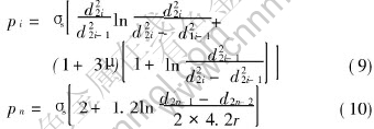
where i=1, 2, ��, n. ��s is yield strength of material, r is the outer round corner radius of element 4.
3 FE SIMULATION AND EXPERIMENT
3.1 Simulation model
The required aluminum alloy double wall cup part is shown in Fig.4 (a). And the FE model used in simulation is shown in Fig.4 (b). The velocity of punch v and the friction factor m1 (between punch and billet) and m2 (between die and billet) and other parameters (marked in Fig.4 (a)) will be discussed during simulation process.
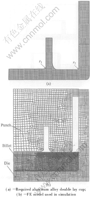
Fig.4 Simulation model
3.2 Forming process
During the forming of aluminum alloy double wall cup, inner wall and outer wall can be formed orderly by controlling metal flow. The following figure (see Fig.5) shows that the inner wall formed first and the outer wall formed subsequently. What��s more, the height of outer wall is lower than that of inner wall at that time. Also, by adjusting the value of parameters marked in Fig.1, the inner wall could be formed later and the outer wall first.
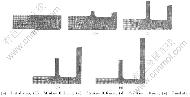
Fig.5 Simulation process of aluminum alloy double wall cup
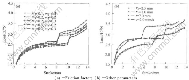
Fig.6 Effect curves of parameters on forming force
3.3 Forming force predicted by FE simulation
The buck forming FE software DEFORMTM was employed to forecast the forming process of multi-layer cylinder parts. It is very important to predict the forming force with FE numerical simulation method. The highest force needed in forming can be used to choose proper hydraulic press and design die structure optimally. The effect of process parameters on forming force is shown in Fig.6.
The friction factor is an important parameter that affects the forming force during bulk metal forming. It can be seen that from Fig.6(a), the effect degree of m2 on the increment of load is higher than that of m1. In Fig.6(b), the lines marked with �� and �� are obtained by reducing the out wall thickness t from 9mm to 7mm and by adjusting the punch velocity from 1mm/s to 2mm/s respectively. It is shown that the needed load is improved obviously. By comparing the lines marked with �� and �� in Fig.6(b) and the line marked with �� in Fig.6(a), it also can be seen that the variation of punch round radius has little effect on load.
3.4 Formed parts
The total forming force of gland bush is 3710kN according to theoretical equation (Eqn.(6)), and the measured force is 4030kN in experiment. And the corresponding values of shell are 3200kN and 3420kN respectively. The difference between theory and experiment only is about 8%. So the values are in good agreement with that of the FE computed results. The formed part is shown in Fig.7.
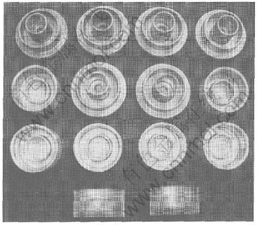
Fig.7 Some experimental parts
4 CONCLUSIONS
Based on the flow control forming principle, the key technologies of CFC during the forming process of multi-lay cylinder parts were studied. The calculation model and formulation of backward extrusion force was proposed. The results calculated by it show good agreement with that of obtained from experiments and FE simulation. According to the shape characteristics of multi-lay cylinder parts, the reasonable technical scheme and die structure were designed to reduce the forming force and improve mechanical properties. Then the required parts, i.e. gland bush and shell, were manufactured successfully.
REFERENCES
[1]Kim Y H, Ryou T K, Choi H J, et al. An analysis of the forging processes for 6061 aluminum-alloy wheels [J]. Journal of Mater Proc Tech, 2002, 123: 270-276.
[2]Bardi F, Cabibbo M, Spigarelli S. An analysis of thermo-mechanical treatments of a 2618 aluminum alloy: study of optimum conditions for warm forging [J]. Journal of Materials Science and Engineering, 2002, A334: 87-95.
[3]Siegert K, Kammerer M, Keppler-Ott T, et al. Recent developments on high precision forging of aluminum and steel [J]. Journal of Mater Proc Tech, 1997, 71: 91-99.
[4]Tomov B I, Gagov V I, Radev R H. Numerical simulations of hot die forging processes using finite element method [J]. Journal of Mater Proc Tech, 2004,153-154: 352-358.
[5]Maccormack C, Monaghan J. Failure analysis of cold forging dies using FEA [J]. Journal of Mater Proc Tech, 2001,117: 209-215.
[6]Vazquez V, Altan T. Die design for flashless forging of complex parts [J]. Journal of Mater Proc Tech, 2000, 98: 81-89.
[7]XIA Ju-chen, DING Yong-xiang, HU Guo-an. Closed Die Forging [M]. Beijing: Mechanical Industry Press. 1993.(in Chinese)
[8]Shan D B, Xu W C, Lu Y. Study on precision forging technology for a complex-shaped light alloy forging [J]. Journal of Mater Proc Tech, 2004,151: 289-293.
[9]Kim Y H, Ryou T K, Choi H J, et al. An analysis of the forging processes for 6061 aluminum-alloy wheels [J]. Journal of Mater Proc Tech, 2002, 123: 270-276.
[10]WU Chun-yin, Hsu Yuan-chuan. The influence of die shape on the flow deformation of extrusion forging [J]. Journal of Mater Proc Tech, 2002, 124: 67-76.
[11]Cherouat A, Saanouni K, Hammi Y. Improvement of forging process of a 3D complex part with respect to damage occurrence [J]. Journal of Mater Proc Tech, 2003,142: 307-317.
[12]Venugopal R A, Ramakrishnan N, Krishna K R. A comparative evaluation of the theoretical failure criteria for workability in cold forging [J]. Journal of Mater Proc Tech, 2003, 142: 29-42.
[13]Wang S I, Seo M K, Cho J R, et al. A study on the development of large aluminum flange using the casting/forging process [J]. Journal of Mater Proc Tech, 2002, 130-131: 294-298.
[14]Yoshimura H, Tanaka K. Precision forging of aluminum and steel [J]. Journal of Mater Proc Tech, 2000, 98: 196-204.
[15]Jensrud O, Pedersen, K. Cold forging of high strength aluminum alloys and the development of new thermomechanical processing [J]. Journal of Mater Proc Tech, 1998, 80-81: 156-160.
[16]XIA Ju-chen, WANG Xin-yun, HU Guo-an, et al. Process analysis and calculation of force of flow control forming for multi-layer cylinder parts [J]. China Mechanical Engineering, 2004,15(1): 91-93.(in Chinese)
Foundation item: Project() supported by HUST Key Research Fund
Received date: 2004-11-30; Accepted date: 2005-01-18
Correspondence: WANG Xin-yun, PhD, Associate Professor; Tel: +86-27-87543491; E-mail: bigaxun@263.net
(Edited by LI Xiang-qun)

