J. Cent. South Univ. (2017) 24: 1288-1298
DOI: 10.1007/s11771-017-3534-5

Dynamics modeling and simulation of a saucer-shaped stratospheric aerostat with an under-slung nacelle
ZHAO Ming(赵明), XIAO Chang(肖畅), ZHOU Ping-fang(周平方), DUAN Deng-ping(段登平)
School of Aeronautics and Astronautics, Shanghai Jiao Tong University, Shanghai 200240, China
 Central South University Press and Springer-Verlag Berlin Heidelberg 2017
Abstract: A new concept stratospheric aerostat is investigated which consists of a saucer-shaped hull, multi-vectored thrusters, and an under-slung nacelle. The design of this aerostat involves tradeoffs between conventional airship and high altitude balloon. The sling connection simplifies structure design significantly, but brings challenges for dynamics analysis. Dynamics modeling for this aerostat is a kind of double-body problem with geometric constraint. Nonlinear dynamics model is established by considering the effects of under-slung nacelle. Oscillation behavior of this double-body system is superposed by a long-period oscillation of the hull and a short-period oscillation of the nacelle. The length of sling only influences the short-period oscillation but the mass ratio of nacelle to main body determines the stability of system. Finally, an envelope about mass ratio and maximal open loop forward thrust as well as speed is presented, where the system is stable.
Key words: saucer-shaped aerostat; double-body; under-slung; dynamics modeling
1 Introduction
Because of long endurance hovering ability, powered aerostats are proposed as stratospheric aerostatic platforms flying at a high altitude of 20 km. Therefore, many advanced projects are competing to develop stratospheric aerostat, such as High-Altitude Airship [1], Hisentinel [2] and Google’s Project Loon [3]. Although some of demonstration aerostats are on the flight test stage, no practicable stratospheric aerostat is launched yet because of huge technical difficulties.
In this work, a saucer-shaped stratospheric aerostat (Fig. 1) is investigated which consists of a cable-envelop hull, four vectored thrusters placed on the equator of the hull symmetrically, and a nacelle containing equipment hangs underneath the inflated envelope by a rope. The design of this new concept aerostat involves tradeoffs between conventional cigar-shaped airship and high altitude super high-pressure balloon.
This work concentrates on the dynamics modeling and simulation with the sling connection effect. Although the sling connection of the hull and the nacelle reduces the complexity of the structure design significantly, it brings challenges for dynamics analysis [4]. Dynamics modeling and simulation about single rigid and elastic airship has been extensive researched [5-7]. But, the interaction between the hull and the under-slung nacelle should be considered which influences stability and flight behavior of the aerostat. It is a difficult double-body dynamics problem. NAGABHUSHAN et al [8, 9] researched dynamics and control characteristics of a quad-rotor heavy lift airship (HLA) with a sling load. According to their studies based on the linearized model, it is of great significance that the dynamic coupling between the vehicle and payload in their response to wind disturbances and control inputs. TISCHLER et al [10] developed a nonlinear, multibody, 6-degree-of- freedom (6DOF) digital simulation to study generic HLA dynamics and control. The model of HLA is a low fineness ratio hull and a small vee-tail airship, while the saucer-shaped aerostat mentioned in this paper is fin-less. Their basic aerodynamic and dynamic properties are quite different. CHEN et al [11] and HAN et al [12] designed control systems for this multi-thruster aerostat without the sling connection effect. So, it is necessary to establish an accurate dynamics model and simulation tool to analyze this special vehicle’s flight behaviors and hence improve its control systems [13, 14].
The contribution of this work is twofold. First, the modeling and simulation results of this aerostat are provided which consider the effects of under-slung nacelle. Second, the length of sling and the mass ratio of nacelle to main body are discussed as parameters of the stability of system, which provides a reference basis for the aerostat design.

Fig. 1 Sketch map of saucer-shaped stratospheric aerostat
2 Model
The aerostat is modeled based on the following assumptions:
1) The hull is considered as a rigid body and equally mass distributed, and the center of mass coincides with geometric center.
2) The nacelle is a rigid ball suspended from the center point on the bottom of the hull by a cable.
3) The cable which connects the hull and the nacelle is weightless and non-extensible.
2.1 Coordinate system
The earth fixed frame, the body fixed frame and the wind frame are classically considered in the derivation of the kinematics and dynamics equations of motion [6]. In this work, the earth fixed frame Ogxgygzg is considered as inertial frame and the wind velocity is given in inertial reference frame. The center of the body fixed frame Oxyz (Fig. 2) is taken at the center of the hull, which is also the gross center of the buoyancy.

Fig. 2 Reference frame of model
The linear and angular velocities are expressed in the body fixed coordinate system as V={u v w}T and  respectively. The position of the aerostat in the earth fixed frame is described by
  while its orientation is given by
  with f roll,θ pitch and ψ yaw angles.
The matrix Tbg and Ebg represent linear and angular velocities’ transformation matrix from the earth fixed frame to the body fixed reference frame respectively. So, kinematic equations of motion for the aerostat are provided as
 (1)
(1)
 (2)
(2)
2.2 Aerodynamics
For simplicity, aerodynamic model is given in this work in the body fixed frame instead of wind frame. Assuming that the wind velocity in the earth fixed frame is Vw, we can get
 (3)
(3)
Thus, the total aerodynamic velocity of aerostat is
 (4)
(4)
Aerodynamic forces and moments are formulated depending on the dynamic pressure and the reference area or volume, and they can be expressed in the following way:
 (5)
(5)
 (6)
(6)
where ρ is air density, V is the reference volume, and dynamic pressure is given by
 (7)
(7)
The first part of MA is steady aerodynamic moment, and the second part is damping. The steady aerodynamic coefficients CX, CZ, CM are given in Fig. 3.
2.3 Added masses
The motion of aerostat in the air generates a surrounding flow field. The additional resistance is generally modeled as added masses [15]. The symmetric added mass matrix is written as

Fig. 3 Steady aerodynamic coefficient
 (8)
(8)
where M11 and M22 are 3×3 submatrices, whose elements will be given in the next section.
The corresponding added mass force and moment can be obtained in vector form as the following equation:

 (9)
(9)
2.4 Gravity, buoyancy and thrust forces
To distinguish from the nacelle, a term of ‘main body’ is used to represent the combination of the hull, the inside gas, the thrusters and other attachments. We use mB to represent the mass of the main body, which is acting at the position  in the
body fixed frame. For the symmetry shape of the aerostat, we get
 (10)
(10)
In a similar way, the center of buoyancy is 
Thus, the gravitational force, the buoyancy and the gravitational and buoyant moments are given by
 (11)
(11)
MGB=0 (12)
The aerostat is controlled by four vectored thrusters instead of aerodynamic control surface. Each thrust vector can rotate 360°around the normal axis of its placed point and they can provide the body with 3 orthogonal forces and 3 orthogonal moments at the same time. They are shown as Fig. 4 in the body coordinate system.
The thrust allocation equations are listed as
 (13)
(13)
where fi is thrust produced by each propeller, rT is the arm of fi, and δi is the thrust angle. Each δi takes the negative direction of oz axis as the starting position, and in the side view, it takes the right hand as the positive direction (red axis in Fig. 4). 
 is virtual control command;
 and
and are real thrusts and their angles, respectively.
So, the allocation Eq. (13) can be rewritten as
τ=h(uδ)uf (14)
where
 (15)
(15)
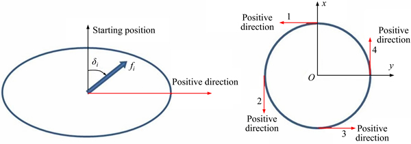
Fig. 4 Thruster position and coordinate definition
Ignoring the control allocation problem, we only assume that the forces and moments acting on the aerostat are  where FT and MT are both 3×1 submatrices.
2.5 Forces on nacelle
For the purposes of investigating the nacelle dynamics, the suspension point is considered to be  in the body fixed frame. By assuming the length of sling is l and the mass of nacelle is mL, the sling vector is given as
The equations that describe the nacelle dynamics are obtained by the flowing steps.
The position of nacelle in the body fixed frame is
 (16)
(16)
Then velocity and acceleration of the nacelle in the inertial system is described by
 (17)
(17)
 (18)
(18)
The nacelle is subject to an isotropic aerodynamic force and experienced by spherical shaped. Aerodynamic interaction due to the thrusts downwash has been ignored. With these assumptions, the aerodynamics of the nacelle can be derived as follows:
 (19)
(19)
where 
The inertia force of the nacelle is
 (20)
(20)
Gravity force of the nacelle is
 (21)
(21)
Therefore, in the body fixed coordinate system, we get the pull force and moment on the hull by sling:
 (22)
(22)
 (23)
(23)
2.6 Equations of double-body system
According to the second Newton law, the general 6DOF dynamics equations can be written as follows:
 (24)
(24)
 (25)
(25)
where mB represents the mass of the main body, including the hull, inside gas, thrusters except nacelle, and I is the moment of inertia.
The general 6-DOF dynamics equations are expanded as


 (26)
(26)


 (27)
(27)


 (28)
(28)


 (29)
(29)


 (30)
(30)

 (31)
(31)
Assuming the pull force acting on the nacelle by sling is  according to Eq. (22), we get
 (32)
(32)
Thus, we can get

 (33)
(33)
Equation (32) can be reformatted as
 (34)
(34)
They can be simplified as
 (35)
(35)
The state variable of this double-body system is given as
 (36)
(36)
According to Eqs. (26)-(31), and Eq. (35), the nonlinear equation of this double-body system can be described by the form:
 (37)
(37)
3 Simulation results
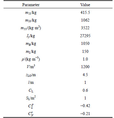
In the numerical simulations presented here, the demo aerostat (Fig. 5) is used as an example. We assume that it flies in the breezeless sky with an equivalent buoyant and weight. Its parameters are given in Table 1.

Fig. 5 Demo aerostat (diameter of 15 m)
Table 1 Parameters of demo aerostat
The simulation results of the zero-input response and the zero-state response are given in the subsections.
3.1 Zero-input response
Assuming the wind field is  we give different initial conditions with
  and
and  Resulting time histories of linear velocity, pitch rate and offset of under-slung nacelle from the simulation are shown in Figs. 6-9, where we find that the different initial state generate different state response characteristics.

Fig. 6 Response result of u in different initial states
When the initial velocity u0 is 3 m/s and other state variables are all zeros, the state variable linear velocity w, pitch rate q and position of under-slung nacelle lx show a damped oscillation and other state variables keep zeros. As u0 is larger enough, 6 m/s, the state variable w, q and lx show an increase tendency before their attenuation.
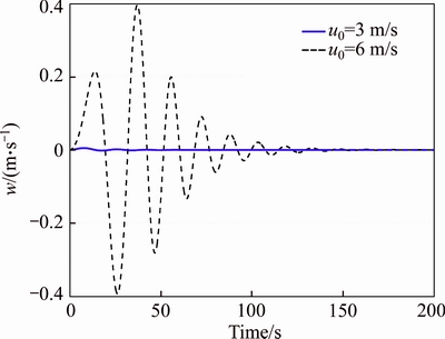
Fig. 7 Response result of w in different initial states
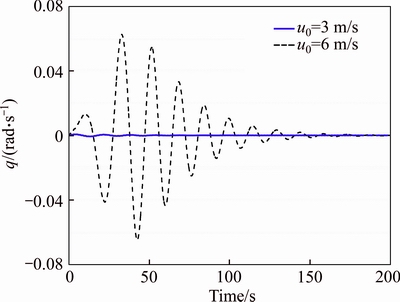
Fig. 8 Response result of q in different initial states

Fig. 9 Response result of lx in different initial states
3.2 Zero-state response
In this simulation, we give forward thrust input as XT=50 N and XT=100 N, respectively, while the initial state variables are all zeros. The results are shown in Figs. 10-13.
The simulation results show that the double-body aerostat system is stable when the input XT=50 N. State variable u shows an overdamping response. w, q and lx show a damped oscillation and other state variables keep zeros. While, when the input increases to 100 N, w, q and lx become divergent and other state variables still keep zeros. This special characteristic has important significance in aerostat design and system control.
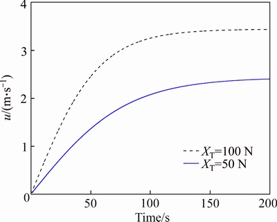
Fig. 10 Response result of u in different inputs
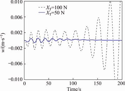
Fig. 11 Response result of w in different inputs
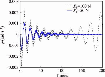
Fig. 12 Response result of q in different inputs

Fig. 13 Response result of lx in different inputs
3.3 Coupling response
In this simulation, we give forward thrust input as XT=50 N and XT=100 N, respectively, while the initial state v0=3 m/s and other variables are all zeros. The results are shown from Fig. 14 to Fig. 17.

Fig. 14 Response result of u (a) and v (b) when v0=3 m/s
The simulation results show that the initial state v0 has little influence on the variable u, w, q and lx. Besides, variable p shows a similar character as q, and variable ly shows a similar character as lx.
According to the simulation results of above all, the double-body aerostat system will be unstable when the input thrust is increased to some extent. If other state variables are all zeros, longitudinal variables u, w, q and lx only follow the longitudinal input XT. If lateral state variables are not zeros, as v0= 3 m/s, all the state variables will follow the longitudinal input XT. This means that the lateral state variables couple with longitudinal input and state, and their stability goes with the longitudinal states. So, we can use the longitudinal input and state to discuss the stability of the double-body system.
4 Optimal design analysis
In this section, we will discuss the effects of aerostat parameters on the input and response, which is going to provide a reference basis for the aerostat design. The length of sling l and the mass ratio of nacelle to main body mL/mB are chosen as variable parameters. We give the different forward thrust as 50 N and 100 N, and the length of sling with 1 m, 5 m and 10 m. The responses are contrasted from Fig. 18 to Fig. 21.
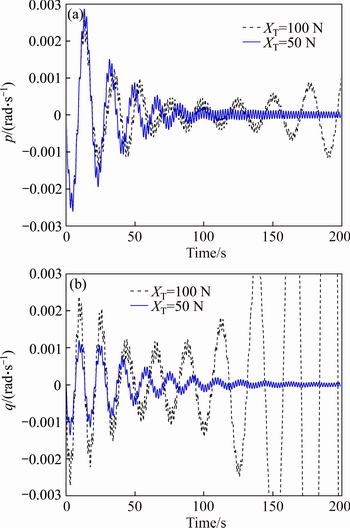
Fig. 15 Response result of p (a) and q (b) when v0=3 m/s

Fig. 16 Response result of w (a) and r (b) when v0=3 m/s
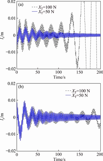
Fig. 17 Response result of lx (a) and ly (b) when v0=3 m/s
The results show that the length of sling changes from 1 m to 10 m, while the stability under the forward thrust of 50 N and 100 N is unchanged. The response is a superposition of natural frequency and swing. When forward thrust is 50 N, natural frequency of system decreases along with the attenuation of system state. The swing is determined by the length of sling, which gives the influence to the system as an effect of simple pendulum.
The mass ratio of nacelle to main body is another factor to determine the character of double-body system. In the following simulation, the mass of nacelle mL is given as 150 kg, 300 kg and 600 kg for samples with the total mass remaining the same and the length of sling being 1 m. The responses under the forward thrust of 100 N and 150 N are contrasted from Fig. 22 to Fig. 25.
When the mass of nacelle is 150 kg, the state response is intensified divergence when the forward thrust increases from 100 N to 150 N. When the mass of nacelle is up to 150 kg, the state response becomes sustained surge. As the mass of nacelle is up to 600 kg, the system keeps convergence under the forward thrust of either 100 N or 150 N. The restoring moment of gravity acting on the hull is determined by the mass of nacelle, and the stability of the system gets strong as the increase of mL obviously. Besides, natural frequency of system response increases with the mass of nacelle.
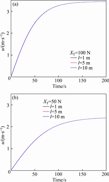
Fig. 18 Response of u at thrust of 100 N (a) and 50 N (b) with different sling lengths
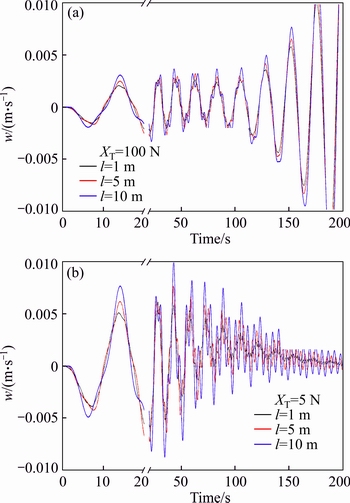
Fig. 19 Response of w at thrust of 100 N (a) and 50 N (b) with different sling lengths

Fig. 20 Response of q at thrust of 100 N (a) and 50 N (b) with different sling lengths
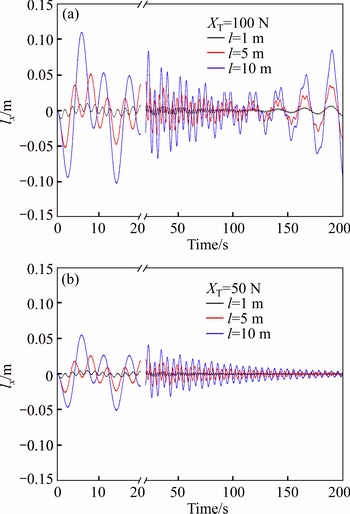
Fig. 21 Response of lx at thrust of 100 N (a) and 50 N (b) with different sling lengths
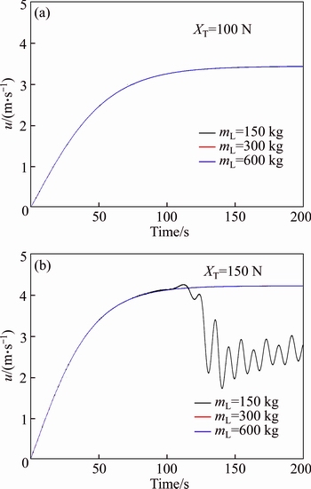
Fig. 22 Response of u at thrust of 100 N (a) and 150 N (b) with different masses
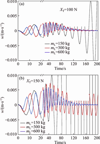
Fig. 23 Response of w at thrust of 100 N (a) and 150 N (b) with different masses
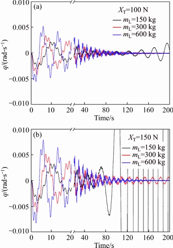
Fig. 24 Response of q at thrust of 100 N (a) and 150 N (b) with different masses
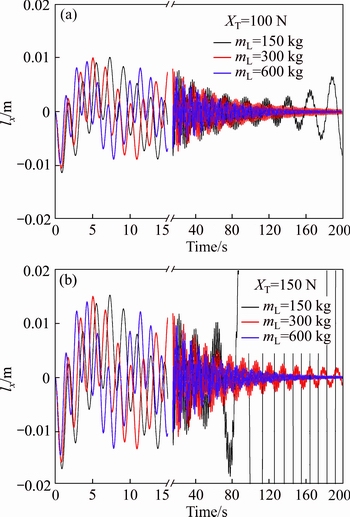
Fig. 25 Response of lx at thrust of 100 N (a) and 150 N (b) with different masses
From the above all, there exists a maximal open loop forward thrust to keep the system stable on a certain mass ratio of nacelle to main body. Meanwhile, the maximal forward thrust corresponds to a maximal stable forward speed without feedback control, which has important significance to aerostat design. By numerical simulation, Fig. 26 gives general envelope about maximal open loop forward thrust and forward speed to keep the system stable on a certain mass ratio of nacelle to main body.

Fig. 26 Maximal forward thrust and forward speed envelope under different mass ratios
5 Conclusions
A new concept aerostat with a saucer-shaped hull and an under-slung nacelle is proposed. This new concept is used to avoid centralized stress by direct connection of the hull and the nacelle. Besides, it is easy to repair and maintain the electric devices in the nacelle. Nonlinear dynamics equations are established at first. Then, the detailed simulation result is provided, and the result is analyzed preliminarily. The double-body aerostat system is not stable when the forward thrust increases large enough. Its oscillation behavior is superposed by a long-period oscillation of the hull and a short-period oscillation of the nacelle. The length of sling is irrelevant to the stability of system but the frequency of swing, while the mass of nacelle has influence on system natural frequency and determines its stability. Afterwards, an envelope about maximal open loop forward thrust and forward speed to keep the system stable on a certain mass ratio is presented.
References
[1] ANDROULAKAKIS S P, JUDY R A. Status and plans of high altitude airship (HAA TM) program [C]// Proceedings of the AIAA Lighter-Than-Air Systems Technology (LTA) Conference. Florida, 2013: 1362-1370.
[2] SMITH S, FORTENBERRY M, LEE M, JUDY R. HiSentinel80: Flight of a high altitude airship [C]// Proceedings of the 11th AIAA Aviation Technology, Integration, and Operations (ATIO) Conference. Virginia, 2011: 6973-6986.
[3] KATIKALA S. GoogleTM project loon [J]. Rivier Academic Journal, 2014, 10(2): 1-6.
[4] ZHANG Li-xue, WANG Zhong-wei, YANG Xi-xiang. Design parameters optimization for stratospheric airship payload mass [J]. Journal of Central South University (Science and Technology), 2013, 44(4): 1368-1372. (in Chinese)
[5] LI Yu-wen, NAHON M, SHARF I. Airship dynamics modeling: A literature review [J]. Progress in Aerospace Sciences, 2011, 47(3): 217-239.
[6] ETKIN B. Dynamics of atmospheric flight [M]. Mineola, New York: Dover Publications, 2005: 56-71.
[7] ETKIN B, REID L D. Dynamics of flight-stability and control [M]. New Jersey: John Wiley & Sons, 1996: 25-39.
[8] NAGABHUSHAN B, TOMLINSON N. Dynamics and control of a heavy lift airship hovering in a turbulent cross wind [J]. Journal of Aircraft, 1982, 19(10): 826-830.
[9] NAGABHUSHAN B L. Dynamic stability of a buoyant quad-rotor aircraft [J]. Journal of Aircraft, 1983, 20(3): 243-249.
[10] TISCHLER M B, RINGLAND R F, JEX H R. Heavy-lift airship dynamics [J]. Journal of Aircraft, 1983, 20(5): 425-433.
[11] CHEN Li, ZHANG Hao, DUAN Deng-ping. Control system design of a multi-vectored thrust stratospheric airship [J]. Proceedings of the Institution of Mechanical Engineers, Part G: Journal of Aerospace Engineering, 2013, 228(11): 2045-2054.
[12] HAN Ding, WANG Xiao-liang, CHEN Li, DUAN Deng-ping. Command-filtered back-stepping control for a multi-vectored thrust stratospheric airship [J]. Transactions of the Institute of Measurement and Control, 2015, 38(1): 93-104.
[13] HAN Ding, WANG Xiao-liang, ZHAO Ming, DUAN Deng-ping. An improved proportional navigation guidance law for waypoint navigation of airships [J] Information Technology and Intelligent Transportation Systems, 2017, 454: 373-383.
[14] WANG Yue ying, WANG Quan bao, ZHOU Ping fang, DUAN Deng-ping. Robust H∞ directional control for a sampled-data autonomous airship [J]. Journal of Central South University, 2014, 21(4): 1339-1346.
[15] FOSSEN T I. Guidance and control of ocean vehicles [M]. John Wiley & Sons Ltd, 1994: 32-35.
(Edited by YANG Bing)
Cite this article as: ZHAO Ming, XIAO Chang, ZHOU Ping-fang, DUAN Deng-ping. Dynamics modeling and simulation of a saucer-shaped stratospheric aerostat with an under-slung nacelle [J]. Journal of Central South University, 2017, 24(6): 1288-1298. DOI: 10.1007/s11771-017-3534-5.
Foundation item: Projects(61175074, 11272205) supported by the National Natural Science Foundation of China
Received date: 2015-11-04; Accepted date: 2016-12-30
Corresponding author: ZHAO Ming, Doctoral Candidate; Tel: +86-18655196066; E-mail: zhaomingpaul@sjtu.edu.cn

