J. Cent. South Univ. Technol. (2010) 17: 544-548
DOI: 10.1007/s11771-010-0520-6
Forming technology of boiling structure on evaporation surface of phase-change heat sink for high-power light emitting diode
XIANG Jian-hua(向建化), YE Bang-yan(叶邦彦), TANG Yong(汤勇), ZHOU Wei(周伟), HU Zhi-hua(胡志华)
School of Mechanical and Automotive Engineering, South China University of Technology, Guangzhou 510640, China
? Central South University Press and Springer-Verlag Berlin Heidelberg 2010
Abstract: Boiling structures on evaporation surface of red copper sheet with a diameter (D) of 10 mm and a wall thickness (h) of 1 mm were processed by the ploughing-extrusion (P-E) processing method, which is one part of the phase-change heat sink for high power (HP) light emitting diode (LED). The experimental results show that two different structures of rectangular- and triangular-shaped micro-grooves are formed in P-E process. When P-E depth (ap), interval of helical grooves (dp) and rotation speed (n) are 0.12 mm, 0.2 mm and 100 r/min, respectively, the boiling structures of triangular-shaped grooves with the fin height of 0.15 mm that has good evaporation performance are obtained. The shapes of the boiling structures are restricted by dp and ap, and dp is determined by n and amount of feed (f). The ploughing speed has an important influence on the formation of groove structure in P-E process.
Key words: phase-change heat sink; boiling structure; high power light emitting diode; ploughing-extrusion
1 Introduction
High power (HP) light emitting diode (LED) is a new type of solid-state light source. There are a number of advantages compared with traditional light sources such as the life time, environmental friendly and energy saving [1-2]. Heat flux reached more than 300 W/cm2 during the  working to rise the junction temperature rapidly in the poor heat dissipation condition, which could lead to short HP LED life time, lower quantum efficiencies, shifted emission wavelength and catastrophic device failure by heat [3-7]. So high heat flux removal is primary concern to control junction temperature in a certain range. In general, approximately 90% or more of the heat is directly dissipated from conduction by heat sink [3]. However, the traditional solid copper heat sink is not able to meet high heat flux conduction. Phase-change heat sink can increase the efficiency of heat transfer by 10 time as compared with the traditional solid heat sink in the same operating conditions [8], and can be widely applied to the heat dissipation of optoelectronic and micro- electronics fields.
The performance of phase-change heat sink is affected by surface boiling performance that is important to the evaporation and cycle of refrigerant, so forming of the boiling structure is essential. Boiling structure is usually fabricated by mechanical methods [9-10], laser machining [11], flame spraying [12], electroplating [13], and sintering [14]. Mechanical methods have been concerned widely by the researchers due to its simple equipment and low cost in recent years. KIM et al [15] investigated the metal flow in the wedge indentation of ‘V’- and ‘W’-shaped tools into a ductile material. XIA et al [16] obtained the spiral integral fin tube using chopping-extruding, including three stages, i.e. chopping, extrusion, and forming. TANG et al [17-18] developed fin structure on the surface of copper tube by pre-rolling ploughing, including two stages, namely pre-rolling and ploughing.
The model of phase-change heat sink as a heat transfer component for HP LED package was analyzed, and boiling structures on the evaporation surface of phase-change heat sink for HP LED were obtained by the ploughing-extrusion (P-E) processing methods in this work. Different structures by P-E processing under different processing parameters were analyzed individually. The matching relationships among the parameters during P-E processing and the law of the constraints were studied.
2 Phase-change heat sink of HP LED package level modeling
The reliability of HP LED depends on good thermal management, so lower thermal resistance of package can obtain better ability of heat dissipation. Fig.1 shows HP LED package structure and the equivalent thermal resistance. Package thermal resistance can be decided by Rth,PKG, which is given by the temperature difference between the junction and the air divided by input power [19]:
 (1)
(1)
where Tj and T0 are the junction temperature in the HP LED and exterior temperature of heat sink, respectively, and Qin is the input power.
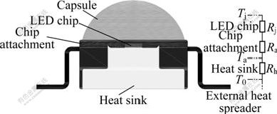
Fig.1 Schematic diagram of HP LED package structure and equivalent thermal resistance (Rj, Ra, and Rh are thermal resistances of LED chip, chip attachment, and heat sink, respectively, and Ta is temperature of chip attachment)
HP LED phase-change heat sink is made up of a vapor chamber, wick and boiling structures (Fig.2). As heat is applied, the fluid at the location immediately vaporizes, and the vapor rushes to fill the vacuum. When vapor comes into contact with the condenser surface, vapor releases its latent heat of vaporization and turns into liquid. Then, the condensed liquid returns to the heat source via capillary action or natural circulation. Higher effective thermal conductivity is obtained due to the high latent heat of a liquid during phase change.
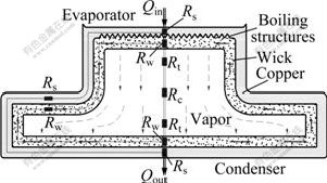
Fig.2 Schematic diagram of HP LED phase-change heat sink structure and principle (Rs, Rw, Rt, and Rc are thermal resistances of solid wall, wick, liquid vapor interface, and vapor core, respectively, and Qout is output heat)
3 Experimental
The experiment was carried out on the lathe C6132A1. The red copper column with a diameter of 10 mm, a thickness of 1 mm was used as the work-piece, and the material of tool was W18Cr4V. The work piece was fixed on the chuck firstly, and P-E tool was installed parallelly to copper columnar axis, then the radial feed parameters of P-E processing were determined, and the lathe started to process. Fig.3 shows the schematic diagram of P-E processing.
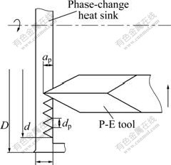
Fig.3 Forming schematic diagram of enhanced boiling structure by P-E processing (D is small end diameter of phase-change heat sink, d is maximal diameter of processing, ap is P-E depth, and dp is interval of helical grooves)
According to the boiling structure forming processed by P-E processing, when tool ploughed the work piece, the ploughing speed was continuously changed. The greatest ploughing speed existed when the tool located at the maximum diameter of the work-piece. Along with the lathe feeding, P-E tool was closed to the center of the work piece gradually, so the ploughing speed reduced synchronously. The relationship among rotation speed n, maximal diameter of processing d and the amount of feed f is given as follows:
 (2)
(2)
where v is the processing speed and t is the processing time.
P-E tool consisted of a ploughing edge, a primary extruding face  a minor extruding face
  a primary forming face Aβ and a minor forming face
  (shown in Fig.4). The P0-P0 cross-section of the tool was a wedge structure whose front end was the ploughing blade.
P-E tool was designed to be thin in shape to make force acting on tool small enough during P-E process, so it could prevent the tool from collapsing. The composite force of tool could be decomposed into the extrusion force and the friction force, which were produced mainly between the work piece and primary/minor extruding faces. The extrusion force and friction force produced from each face were equal in quantity and opposite in direction. So, the relationship between the primary/minor
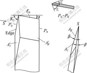
Fig.4 Schematic diagrams of P-E tool (Eα is flank of tool, Kγ and α are rake and clearance angle of tool, respectively)
extruding angles should satisfy the following condition [20]:
 (3)
(3)
where γ0 is the primary extruding angle,  is the minor extruding angle, β is the primary forming angle, and
 is the minor forming angle.
4 Results and discussion
4.1 Analysis of P-E processing
P-E processing related to ploughing processing and metal plastic deformation, including three stages, namely ploughing, extruding and forming. Firstly, when work piece rotated, the edge of P-E tool ploughed the surface of copper and split the metal little by little. The metal split by ploughing edge started to flow bilaterally towards the extruding face. Secondly, since surface metal was split, the extruding faces of the tool squeezed the metal along the radial direction to form grooves. So the metal at the foot and the middle of the groove flowed bilaterally and reached the groove fringe. Finally, the fin was formed in this stage. The metal on the rightward of the tool was squeezed to make the metal higher and higher to form fin by the primary/minor forming faces.
4.2 Influence of amount of feed (f) and P-E depth (ap)
Figs.5 and 6 show the experiment results at different amount of feed f and P-E depth ap, on the condition that the primary extruding angle  was 30?, the minor extruding angle was 10?, the primary forming angle β was 15?, and the minor forming angle was 5?. According to the processing, the interval of helical grooves dp was determined by f. Fig.5(a) shows the rectangular-shaped grooves at the interval of helical grooves dp=0.36 mm and ap=0.25 mm. When the interval of helical grooves was larger, the deformation areas did not affect each other, the structure of groove and the formation mechanism were the same as those of single micro-groove. In forming process, there was no effect on the latest adjacent groove, and the minor extruding face
  and the minor forming face did not trim the formed groove. So the rectangular-shaped grooves were formed by P-E processing. Along with decreasing the
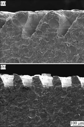
Fig.5 Rectangular-shaped grooves in P-E processing: (a) dp=0.36 mm, ap=0.25 mm; (b) dp=0.25 mm, ap=0.15 mm
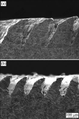
Fig.6 Triangular-shaped grooves in P-E processing: (a) dp= 0.25 mm, ap=0.25 mm; (b) dp=0.20 mm, ap=0.12 mm
interval of helical grooves dp and P-E depth ap, the top metal of the rectangular-shaped fin was deformed by compression. Fig.5(b) shows the structure at the interval of helical grooves dp=0.25 mm and P-E depth ap= 0.15 mm.
The interval of helical grooves dp and P-E depth ap had the greatest influence on the formation of micro-grooves. When the interval of helical grooves dp was larger or P-E depth ap was smaller, rectangular fins were obtained between the two grooves, as shown in Fig.5.
Fig.6(a) shows the triangular-shaped groove structure obtained at the interval of helical grooves dp=0.25 mm and P-E depth ap=0.25 mm. When the interval of helical grooves dp was reduced or P-E depth ap was increased, the deformation areas contacted each other, the newly formed grooves interfered on the latest adjacent formed grooves. The metal between the grooves yielded under the extruding force by minor forming face trimmed by minor forming face, and bended along the normal direction of minor forming face. Because the main forming angle β was larger than the minor one , the inclination angle of groove wall formed by main forming face Aβ was larger than that formed by minor forming face . Due to bending, the inward bend of the inclination angle of the last groove wall formed by main forming face Aβ was lessened. Meanwhile, the triangular-shaped grooves were narrowed under the trimming of the minor forming face , the fin grew higher, and the triangular-shaped grooves became deeper and narrower. When the ratio of depth to width of triangle-groove was increased, the solid surface could accumulate liquid and steam so that it had good wetting properties, which was favorable to boiling.
Under the extrusion from minor extruding face and minor forming face , the metal on the groove wall flowed to the groove top and the fin was higher than the primitive copper surface. At the same time, minor forming face pushed the redundant metal between the grooves to the formed adjacent groove, so the latest formed groove was narrowed and triangular-shaped grooves with the sharp top were formed. When amount of feed f was reduced, the height of fins descended under the trimming of the minor forming face . Further analysis from the experimental results indicated that the interval of helical grooves dp was determined by the amount of feed f, and the groove structure in P-E processing was directly affected by P-E depth ap and the interval of helical grooves dp. Fig.6(b) shows the triangular-shaped groove structures with a fin height of 0.15 mm were obtained at the interval of helical grooves dp=0.2 mm and P-E depth ap=0.12 mm.
4.3 Influence of ploughing speed
According to forming process by P-E processing, P-E tool fed by lathe from the maximum diameter to the center of the work piece gradually, so the ploughing speed was continuously changed. When the tool located at the maximum diameter of the work piece, the greatest ploughing speed was hold. P-E tool was close to the center of the work piece gradually, so the ploughing speed was reduced synchronously. At the time when the tool sticked to copper due to the lower ploughing speed, so the groove structure could not be obtained. The rotational rate of basic shaft should not be too small. Experimental results indicated that at n=100 r/min, the minimal ploughing speed was greater than the minimal non-sticking speed.
In P-E processing, the interval of helical grooves dp and P-E depth ap were vital to the formation of grooves. Furthermore, when the parameters were changed, two kinds of structures were obtained. Since the tool was definitive, two kinds of structures were confined by the interval of helical grooves dp and P-E depth ap. Meanwhile, the amount of feed f and the interval of helical grooves dp were restricted each other, so were the interval of helical grooves dp and P-E depth ap. Define dpcv is the critical value of dp, apcv is the critical value of ap in P-E processing to form triangular-shaped groove structure, and nmsv is the minimal non-sticking speed at the minimum radius of n, we have
 (4)
(4)
For rectangular-shaped groove structure (Fig.5), we have
 (5)
(5)
For triangular-shaped groove structure (Fig.6), we have
n<nmsv (6)
5 Conclusions
(1) Micro-groove boiling structures on the evaporation surface of phase-change heat sink for HP LED with a diameter of 10 mm and a wall thickness of 1 mm can be obtained by P-E processing. When the interval of helical grooves, P-E depth, and rotational speed are chosen as 0.2 mm, 0.12 mm, and 100 r/min, respectively, triangle-shaped grooves with better wetting properties are fabricated.
(2) Two different structures of the grooves are formed in P-E processing, including the rectangular- shaped and triangular-shaped grooves. Two kinds of boiling structures obtained in P-E processing are restricted together by the interval of helical grooves dp and P-E depth ap. The interval of helical grooves dp depends on the rotational speed n and amount of feed f in the processing, and there is a relationship between P-E depth ap and rotational speed n.
(3) In P-E processing, the ploughing speed is changed continuously. When the tool is located at the center of the work piece, ploughing speed is minimal. The micro-groove boiling structures can be obtained when the minimal ploughing speed is higher than the minimal non-sticking speed nmsv.
References
[1] JOHN E, AMBER A, MIKE B, JAYESH B, KRISTIN L B, DAVE E, KEVIN H, JAMES I, MICHAEL L, PHIL R, DAVID S. High efficiency GaN-based LEDs and lasers on SiC [J]. Journal of Crystal Growth, 2004, 272(1/4): 242-250.
[2] STEIGERWALD D A, BHAT J C, COLLINS D, FLETCHER R M, HOLCOMB M O, LUDOWISE M J, MARTIN P S, RUDAZ S L. Illumination with solid state lighting technology [J]. IEEE Journal on Selected Topics in Quantum Electronics, 2002, 8(2): 310-320.
[3] ADAM C, SAMUEL G. Thermal effects in packaging high power light emitting diode arrays [J]. Applied Thermal Engineering, 2009, 29(2/3): 364-371.
[4] NARENDRAN N, GU Y, FREYSSINIER J P, YU H, DENG L. Solid-state lighting: Failure analysis of white LEDs [J]. Journal of Crystal Growth, 2004, 268(3/4): 449-456.
[5] ARIK M, PETROSKI J, WEAVER S. Thermal challenges in the future generation solid state lighting applications: Light emitting diodes [C]// The Eighth International Society Conference. San Diego, 2002: 113-120.
[6] ARIKA M, BECKERB C, WEAVER S, PETROSKI J. Thermal management of LEDs: Package to system [C]// Proceedings of SPIE: The Third International Conference on Solid State Lighting. San Diego, 2004: 64-75.
[7] NARENDRAN N, GU Y. Life of LED-based white light sources [J]. Journal of Display Technology, 2005, 1(1): 167-171.
[8] VASILIEV L L. Micro and miniature heat pipes-electronic component coolers [J]. Applied Thermal Engineering, 2008, 28(4): 266-273.
[9] YU C K, LU D C. Pool boiling heat transfer on horizontal rectangular fin array in saturated FC-72 [J]. International Journal of Heat and Mass Transfer, 2007, 50(17/18): 3624-3637.
[10] TANG Yong, CHI Yong, CHEN Jin-chang, DENG Xue-xiong, LIU Lin, LIU Xiao-kang, WAN Zhen-ping. Experimental study of oil-filled high-speed spin forming micro-groove fin-inside tubes [J]. International Journal of Machine Tools and Manufacture, 2007, 47(7/8): 1059-1068.
[11] YU Hui, LI Biao, ZHANG Xin. Flexible fabrication of three-dimensional multi-layered microstructures using a scanning laser system [J]. Sensors and Actuators A: Physical, 2006, 125(2): 553-564.
[12] ARCONDEGUY A, GASGNIER G, MONTAVON G, PATEYRON B, DENOIRJEAN A, GRIMAUD A, HUGUET C. Effects of spraying parameters onto flame-sprayed glaze coating structures [J]. Surface and Coatings Technology, 2008, 202(18): 4444-4448.
[13] JOSEPH P O’K, KAREN F M, YVELINE G, JOAQUIN T, PATRICK V K, GABRIEL M C. Room temperature electroless plating copper seed layer process for damascene interlevel metal structures [J]. Microelectronic Engineering, 2000, 50(1/4): 473-479.
[14] SCOTT G L, MASSOUD K. Pool-boiling CHF enhancement by modulated porous-layer coating: Theory and experiment [J]. International Journal of Heat and Mass Transfer, 2001, 44(22): 4287-4311.
[15] KIM W, KAWAI K, KOYAMA H. Metal flow in wedge indentation of V- and W-shaped tools [J]. Journal of Materials Processing Technology, 2007, 189(1/3): 392-400.
[16] XIA Wei, WU Bin, TANG Yong, YE Bang-yan. On chopping-extrusion of integral-fin copper tubes [J]. Journal of Materials Processing Technology, 2003, 138(1/3): 385-389.
[17] TANG Yong, XIA Wei, LIU Shu-dao, ZENG Zhi-xin, YE Bang-yan. Fin formation model during pre-roll ploughing of copper 3D outside fin tube [J]. Transactions of Nonferrous Metals Society of China, 2001, 11(5): 712-716.
[18] XIANG Jian-hua, TANG Yong, YE Bang-yan, ZHOU Wei, YAN Hui, HU Zhi-hua. Compound forming technology of outside 3D integral fin of copper tubes [J]. Transactions of Nonferrous Metals Society of China, 2009, 19(2): 335-340.
[19] WANG Chun-jun. Advanced thermal enhancement and management of LED packages [J]. International Communications in Heat and Mass Transfer, 2009, 36(3): 245-248.
[20] CHI Yong, TANG Yong, CHEN Jin-chang, DENG Xue-xiong, LIU Lin, WAN Zhen-ping, LIU Xiao-qing. Forming process of cross-connected finned micro-grooves in copper strips [J]. Transactions of Nonferrous Metals Society of China, 2007, 17(2): 267-272.
Foundation item: Projects(50436010, 50675070) supported by the National Natural Science Foundation of China; Project(07118064) supported by the Natural Science Foundation of Guangdong Province, China; Project(U0834002) supported by the Joint Fund of NSFC-Guangdong of China; Projects(SY200806300289A, JSA200903190981A) supported by Shenzhen Scientific Program, China
Received date: 2009-08-24; Accepted date: 2009-12-25
Corresponding author: TANG Yong, Professor; Tel/Fax: +86-20-87114634; E-mail: ytang@scut.edu.cn
(Edited by CHEN Wei-ping)

