Dilation angle variations in plastic zone around tunnels in rocks-constant or variable dilation parameter
��Դ�ڿ������ϴ�ѧѧ��(Ӣ�İ�)2018���10��
�������ߣ�Hamed MOLLADAVOODI Marzieh RAHMATI
����ҳ�룺2550 - 2566
Key words��dilation; post-peak behavior; plastic zone; strain softening
Abstract: Dilation angle is a significant parameter needed for numerical simulation of tunnels. Even though dilation parameter is physically variable and dependent on confinement and experienced shear plastic strain based on the existing dilation models, numerical simulations of tunnels and underground openings with constant dilation parameter usually lead to satisfactory results in practical use. This study aims to find out why constant dilation angle is enough under practical conditions to simulate numerically tunnels and underground excavations in spite of the fact that dilation angle is variable in laboratory and experimental scale. With this aim, this work studies how mobilized dilation angle varies in a plastic zone surrounding a tunnel. For the circular tunnel under uniform in situ stress field, the stepwise finite difference approximation analytical solution considering strain softening rock mass behavior with mobilized dilation angle was used to study how mobilized dilation angle varies in plastic zone around tunnel under very different conditions. In practical conditions determined in this study, dilative behavior of all over the plastic zone around the tunnel can be approximated to constant dilation angle in the middle region of the plastic zone. Moreover, the plastic zone displacements for mobilized and constant dilation angle models are compared with each other. Further investigation under more general non-uniform in situ stress conditions and non-circular tunnels is performed by using the commercial finite difference software to numerically simulate the Mine-by experimental tunnel of AECL (Atomic Energy of Canada Limited) and the arched tunnel. Although the Mine-by and arched tunnels were numerically simulated based on the mobilized dilation angle model, the variability associated with dilation angle around the simulated Mine-by and arched tunnels is insignificant, and dilation angle is approximately constant in the plastic zone.
Cite this article as: Hamed MOLLADAVOODI, Marzieh RAHMATI. Dilation angle variations in plastic zone around tunnels in rocks-constant or variable dilation parameter [J]. Journal of Central South University, 2018, 25(10): 2550�C2566. DOI: https://doi.org/10.1007/s11771-018-3935-0.

J. Cent. South Univ. (2018) 25: 2550-2566
DOI: https://doi.org/10.1007/s11771-018-3935-0

Hamed MOLLADAVOODI, Marzieh RAHMATI
Department of Mining and Metallurgy, Amirkabir University of Technology, Tehran, Iran
 Central South University Press and Springer-Verlag GmbH Germany, part of Springer Nature 2018
Abstract: Dilation angle is a significant parameter needed for numerical simulation of tunnels. Even though dilation parameter is physically variable and dependent on confinement and experienced shear plastic strain based on the existing dilation models, numerical simulations of tunnels and underground openings with constant dilation parameter usually lead to satisfactory results in practical use. This study aims to find out why constant dilation angle is enough under practical conditions to simulate numerically tunnels and underground excavations in spite of the fact that dilation angle is variable in laboratory and experimental scale. With this aim, this work studies how mobilized dilation angle varies in a plastic zone surrounding a tunnel. For the circular tunnel under uniform in situ stress field, the stepwise finite difference approximation analytical solution considering strain softening rock mass behavior with mobilized dilation angle was used to study how mobilized dilation angle varies in plastic zone around tunnel under very different conditions. In practical conditions determined in this study, dilative behavior of all over the plastic zone around the tunnel can be approximated to constant dilation angle in the middle region of the plastic zone. Moreover, the plastic zone displacements for mobilized and constant dilation angle models are compared with each other. Further investigation under more general non-uniform in situ stress conditions and non-circular tunnels is performed by using the commercial finite difference software to numerically simulate the Mine-by experimental tunnel of AECL (Atomic Energy of Canada Limited) and the arched tunnel. Although the Mine-by and arched tunnels were numerically simulated based on the mobilized dilation angle model, the variability associated with dilation angle around the simulated Mine-by and arched tunnels is insignificant, and dilation angle is approximately constant in the plastic zone.
Key words: dilation; post-peak behavior; plastic zone; strain softening
Cite this article as: Hamed MOLLADAVOODI, Marzieh RAHMATI. Dilation angle variations in plastic zone around tunnels in rocks-constant or variable dilation parameter [J]. Journal of Central South University, 2018, 25(10): 2550�C2566. DOI: https://doi.org/10.1007/s11771-018-3935-0.
1 Introduction
The excavation of an underground opening disturbs the primary stress state, leading to stress redistribution and deformation of rock mass around the excavation boundary. When the excavation- induced stresses on the boundary of an underground excavation reach the rock mass strength, failure of rock mass occurs and leads to damage zone around it [1]. In highly stressed ground, both the depth of damage (yield) and the amount of deformation can have significant implications, especially for support design [2]. Therefore, numerical simulation of damage zone characteristics such as location, shape, depth and extension angle is vital for design and support considerations. Some numerical methods can be applied to modeling the elastoplastic deformation of an underground opening, such as general particle dynamics (GPD) [3�C6] and peridynamics (PD) [7, 8]. For practical design applications, elasto-plastic constitutive models are widely implemented in numerical simulation of the excavation damage zone. The characterization of a rock mass behaviour in plasticity theory framework needs parameters defining pre-peak rock mass behavior, an evolving failure criterion and a stress/ strain relationship for post-peak rock mass behavior. One of the most important parameters to characterize rock volumetric behavior in post-peak region is dilation angle that depends on confinement and experienced plastic strain in laboratory tests scale. Consequently, dilation models [1, 9�C13] have been proposed to take into account variability associated with dilation angle in laboratory scale. The most accurate model adds complexity to the analyses and also requires additional input parameters beyond those which are typically obtained from laboratory testing. The selection of a dilation model for implementation in numerical models remains a significant problem in rock engineering practice [14].
On the other hand, numerical simulations of tunnels and underground openings with constant dilation parameter usually lead to satisfactory results in practical use such as the Mine-by test tunnel simulation by ZHAO et al [11]. It seems that dilation angle is almost constant in excavation damage zone around a tunnel under practical engineering conditions. WALTON et al [15] compared plastic zone displacements for mobilized and constant dilation angle models in perfectly plastic or elastic-brittle-plastic rock mass behavior and found statistically the mobilized dilation angle can be well approximated through the use of an appropriate best-fit constant dilation angle. WALTON et al [15] proposed a practical methodology for the selection of a constant dilation angle for use in continuum numerical models.
The main purpose of this paper is to find out why constant dilation angle is enough under practical engineering conditions to simulate numerically tunnels and underground excavations despite the fact that dilation is physically variable in laboratory tests. It is of interest, for practical engineering analyses, to comprehend the situations where accurate dilation models are really necessary and where simplified dilation models may be sufficient. In this study, it is aimed at determining practical conditions in which dilation angle is constant in plastic zone around a tunnel, so simple dilation model is adequate to analysis.
To meet the objectives of this study, the circular tunnels under uniform in situ stress field were analyzed by the stepwise finite difference approximation analytical solution considering strain softening rock mass behavior with mobilized dilation angle under very different conditions in order to study how mobilized dilation angle varies in the plastic zone around tunnel. Further investigation under more general non-uniform in situ stress conditions and non-circular tunnels is performed by using the commercial finite difference software to numerically simulate the Mine-by and the arched tunnels. The objective is not to present a general guideline on the dilation parameter selection, which is unrealistic given the complexity of ground conditions, but rather to acquire additional and accurate insight into dilation angle variations in plastic zone around tunnels.
2 Dilation surface and minimum principal stress-shear plastic strain path
Dilation angle is an important input parameter to describe post-peak rock behavior. Dilation parameter indicates the volume change as a result of shear deformation in rocks [16]. According to the existing dilation models [1, 10, 14], a more general relation for dilation angle (��) that is dependent on minimum principal stress (��3) and experienced shear plastic strain (��p) in plastic zone around tunnel can be written as follows:
��=��(��3, ��p) (1)
In this work, dilation angle model of WALTON [12] provides the basis for further investigation. This model can be expressed as follows [12]:
 (2)
(2)
where

where �� is the pre-mobilization curvature, ��m is the plastic shear strain at the peak dilation angle, ��* isthe decay rate of the dilation angle, ��0 is the sensitivity parameter of peak dilation at low confinement, �¡� is the sensitivity parameter of peak dilation at high confinement, f is the friction angle, and ��c is the uniaxial compressive strength.
According to Eq. (1), in a coordinate system of dilation angle, minimum principal stress (��3) and shear plastic strain (��p), a three-dimensional surface corresponding to dilation angle function represents graphically dilative behavior of rock mass. Furthermore, in excavation damage zone around a tunnel the maximum radial stress and the minimum shear plastic strain occur at the elastic-plastic boundary, but the minimum radial stress and the maximum shear plastic strain occur at the tunnel wall as illustrated in Figure 1. In a coordinate system of minimum principal stress (��3) and shear plastic strain (��p), the loci of minimum principal stress-shear plastic strain states of rock elements in plastic zone are located on a curve, in this paper called the path of minimum principal stress-shear plastic strain in plastic zone, intersecting the minimum principal stress-shear plastic strain states of the tunnel wall to the elastoplastic boundary as shown in Figure 1.
The curve called the path of minimum principal stress-shear plastic strain in plastic zone surrounding the tunnel can be calculated by using either analytical or numerical methods. Intersecting the dilation angle surface and the path of minimum principal stress-shear plastic strain leads to better understanding how dilation angle changes in excavation damage zone around the tunnel.
3 Methodology
Each rock mass has special and particular dilation angle surface in a geometric coordinate system of minimum principal stress (��3), shear plastic strain (��p) and dilation angle (��) according to Eq. (1). The position of ��minimum principal stress�C shear plastic strain path�� relative to the dilation angle surface, which indicates how dilation angle changes in plastic zone, depends on the minimum principal stress at the elastic-plastic boundary (��re) and ratio of shear plastic strain at the tunnel wall (��wall) to decay rate of the dilation angle (��*) as shown in Figure 8. The ratio of (��wall/��*) affects the dilation angle variations in plastic zone rather than either the decay rate of the dilation angle (��*) or the shear plastic strain at the tunnel wall (��wall) alone.

Figure 1 Path of minimum principal (radial) stress-shear plastic strain in plastic zone around a hypothetical tunnel
Based on the dilation models of WALTON et al [14] and ALEJANO et al [10], the more the ratio of (��wall/��*) increases, the more the ratio of mobilized to peak dilation angle (��mobilized/��peak) in post-peak region decreases in an exponential manner as shown in Figure 2.
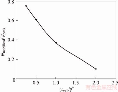
Figure 2 Variations in ratio of mobilized to peak dilation angle with increasing in ratio of shear plastic strain at tunnel wall to decay rate of dilation angle (��wall/��*) in post-peak region
Another important parameter affecting the relative position of minimum principal stress-shear plastic strain path with respect to dilation angle surface is the radial (minimum principal) stress at the elastic-plastic boundary (��re). The radial (minimum principal) stress at the elastic-plastic boundary (��re) depends on not only in situ stress but also rock mass strength parameters. In a circular tunnel under isotropic in situ stress condition, the radial (minimum principal) stress at the elastic- plastic boundary (��re) can be calculated based on the Mohr-Coulomb criterion as follows [17]:
 ��
��
 ��
��
 (3)
(3)
where C is cohesion, f is friction angle, ��c is uniaxial compressive strength, and ��0 is isotropic in situ stress. Furthermore, the Hoek-Brown criterion results in the radial (minimum principal) stress at the elastic-plastic boundary (��re) as follows [18]:
��re =��0�CM��c (4)
In which

where mp is a constant of rock nature, and sp is a constant showing the extent to which rock was broken.
In this research, in order to investigate dilation angle variations in plastic zone around a circular tunnel under isotropic primary stress condition, all possible conditions of radial (minimum principal) stress at the elastic-plastic boundary (��re) and ratio of (��wall/��*) for sedimentary and crystalline rocks were divided into some cases with more limited but uniform conditions by trial and error as presented in Tables 1 and 5. As dilation of sedimentary rocks is more dependent on confinement than dilation of crystalline igneous rocks based on the dilation model of WALTON [12], the dilative behavior of plastic zone around tunnels excavated in sedimentary and crystalline rock masses was studied separately in this paper. To study how dilation angle changes in both sedimentary and crystalline igneous rocks, the sandstone section of the Ghomroud tunnel in Iran and the granite rock mass of the Kobbskaret tunnel in Sweden were selected as only typical projects for further investigation. All radial stress conditions at the elastoplastic boundary were divided hypothetically into three different levels of high, intermediate and low in accordance with a wide variety of tunnel overburdens from deep to shallow tunnels in reality. Afterward, at each radial stress level, some cases with a wide range of (��wall/��*) were presumed to take into account a wide variety of tunnel plastic behavior as presented in Tables 1 and 5.
Subsequently, a stepwise analytical solution programmed in a mathematical software environment was implemented to determine the minimum principal (radial) stress-shear plastic strain path and dilation angle variation in each case of Tables 1 and 5. In order to investigate the plastic zone behavior, the peak and residual failure criteria and the post-failure rock mass relations(drop modulus) proposed by ALEJANO et al [19] with mobilized dilation angle of WALTON [12] were implemented in stress-based finite difference approximation numerical procedure proposed by LEE et al [20]. This method can take into account strain softening behavior of rock mass in post-peak region with mobilized dilation angle. To study the plastic zone behavior around the tunnel with a stepwise analytical solution, it is usually assumed that the plastic zone is composed of N concentric annuli where jth annulus is bounded by two circles of normalized radii ��(j�C1) and ��(j) as shown in Figure 3 [20]. LEE et al [20] concluded that choosing the number of annuli (N) of the plastic zone in the range of hundreds can give very accurate prediction of radial displacements and stresses. They suggested that if N��500, the calculated displacement and stress are close enough to the exact solution. In this study, the plastic zone around the tunnel is divided into 500 concentric rings.
Thickness of rings is not equal with each other, and it is determined during the numerical process to satisfy the equilibrium condition [20]. The governing equations of the problem are stress equilibrium, strain compatibility and constitutive equations which have differential form. The calculations were done from the outer boundary of plastic zone to the tunnel boundary by finite difference approximation method. This stepwise algorithm of analytical solution has been programmed in a mathematical software environment, and it had already been implemented in analysis of the Ghomroud tunnel by KATEBIAN et al [21].
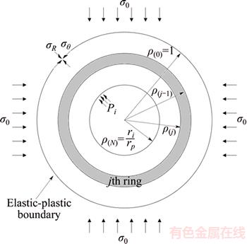
Figure 3 Plastic zone with finite number of concentric rings [20]
4 Finding and results
4.1 Sedimentary rocks
All analyzed cases including all possible conditions of radial stress at the elastic-plastic boundary (��re) and ratio of (��wall/��*) for sedimentary rocks can be seen in Table 1.
4.1.1 High stress level
The sandstone section of the Ghomroud tunnel, with input parameters in Table 2, was selected as a typical project representing high radial stress level conditions at the elastic-plastic boundary (deep tunnels) because the minimum principal (radial) stress at the elastic-plastic boundary of the Ghomroud tunnel with overburden of 650 m is about 8 MPa calculated based on Eq. (4). The parameters of the sandstone section of the Ghomroud tunnel are presented in Table 2.
where  is Poisson ratio, ��0 is isotropic in situ stress, and GSIpeak is the peak value of geological strength index before applying loads. Moreover, to study the cases 11�C15 in Table 1, a wide range of dilation angle decay rate (��*) was selected as input parameter to investigate effects of ratio of (��wall/��*) on dilation behavior of plastic zone around the tunnel. Figure 4 shows radial profiles of dilation angle variation in plastic zone around the Ghomroud tunnel for various ratios of (��wall/��*) in accordance with cases 11�C15.
As shown in Figure 4, three regions consisting of tunnel wall, middle and elastic-plastic boundary parts in all radial profiles of dilation angle in plastic zone around the Ghomroud tunnel can be distinguishable. The tunnel wall and elastic-plastic boundary regions constitute small portions of all the radial dilation angle profiles in the plastic zone around the Ghomroud tunnel. However, the middle region forms significant portion of all the radial dilation angle profiles in the plastic zone.
As can be seen in Figure 4, dilation is not fully mobilized in elastic-plastic boundary region due to low experienced shear plastic strain and high confinement in this region, so dilation angle is low in the elastic-plastic boundary region. Due to low dilatancy and shear plastic strain in the elastic- plastic boundary region, volumetric strain (convergence) resulted from this region is insignificant. Therefore, this region has little influence on dilative behavior of the whole plastic zone. In the ranges of 0.25�ܦ�wall/��*��3, variability associated with dilation angle in the middle region, substantial portion of the plastic zone, is insignificant. Although dilation angle is variable in the tunnel wall region, the tunnel wall region is extremely thin, and the proportion of tunnel wall region displacement to the plastic zone convergence is low. Therefore, the range of 0.25�ܦ�wall/��*��3 covers the conditions at high stress level which constant dilation angle can be used in practical engineering tunnel design.
Table 1 All cases analyzed by using a stepwise analytical solution for sedimentary rocks
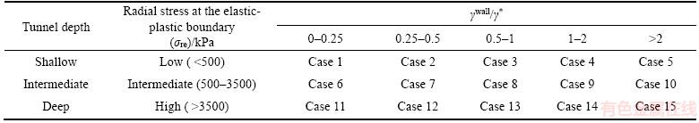
Table 2 Data set obtained from sandstone section of Ghomroud tunnel [22]
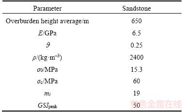

Figure 4 Radial profiles of dilation angle variations in plastic zone around Ghomroud tunnel for various ��wall/��* at high stress level (r: radial distance, a: tunnel radius)
In cases encompassing ranges of ��wall/��*��0.25, the dilation angle has decreasing trend from the tunnel wall toward the elastic-plastic boundary and depends solely on radial stress. The effect of experienced shear plastic strain on dilative behavior of the plastic zone around the tunnel is negligible across these ranges, and dilation angle in the middle region is so variable that a constant dilation angle could not represent dilative behavior of the plastic zone within these conditions.
Furthermore, in cases covering the ranges of ��wall/��*��3, dilation angle has rising trend within the middle region of the radial dilation angle profile from the tunnel wall toward the elastic-plastic region. Due to high radial stress and experienced shear plastic strain in this range, dilation angle variations are insignificant.
4.1.2 Intermediate stress level
To investigate how dilation angle behaves in a plastic zone around a tunnel at intermediate stress level, the Ghomroud tunnel was analyzed by using stepwise finite difference approximation analytical method with hypothetical overburden of 150 m under isotropic in situ stress of 3.5 MPa. The minimum principal (radial) stress at the elastic- plastic boundary of the 2.5 m radius tunnel is about 1 MPa classified as intermediate stress level according to Table 1. Figure 5 shows the radial profiles of dilation angle along the plastic zone around the tunnel with various ratios of shear plastic strain at tunnel wall to decay rate of dilation angle (��wall/��*) in accordance with cases 6�C10 in Table 1.
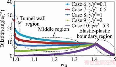
Figure 5 Radial profiles of dilation angle along plastic zone around tunnel at intermediate stress level (r: radial distance, a: tunnel radius)
In cases at intermediate stress level similar to high stress level, three separate regions including tunnel wall, middle and elastic-plastic boundary regions are distinguishable. Due to low experienced shear plastic strain and high confinement in the elastic-plastic boundary zone, dilation angle is not fully mobilized.
In ranges of ��wall/��*, dilation angle along the plastic zone has decreasing trend from the tunnel wall toward the elastic-plastic boundary; as a result, dilation angle is so variable that it could not be represented by a constant parameter. Due to low experienced shear plastic strain in these ranges, dilation behavior depends solely on radial stress level.
Due to low experienced shear plastic strain and high confinement in the elastic-plastic boundary zone, dilation angle is not fully mobilized, and volumetric strain (convergence) resulted from this region is insignificant. Therefore, this region has little influence on dilative behavior of the whole plastic zone.
In cases covering the ranges of 0.25�ܦ�wall/��*��3, variability associated with dilation angle in the middle region, substantial portion of the plastic zone, is almost insignificant. Although dilation angle is variable in the tunnel wall region, the tunnel wall region is extremely thin, and the proportion of tunnel wall region convergence to the plastic zone displacement is low. Therefore, the dilation angle can be reasonably regarded as a constant parameter in whole of the plastic zone. However, dilative behavior of the plastic zone around the tunnel could not be represented by a constant parameter within the ranges of ��wall/��*, for dilation angle profile has increasing trend in the middle region from the tunnel wall toward the elastic-plastic region across these ranges.
4.1.3 Low stress level
In order to study how dilation angle changes in plastic zone around the tunnel under low stress level (low overburden), the circular Ghomroud tunnel by hypothetical overburden of 30 m under isotropic in situ stress of 1 MPa was analyzed by using the stepwise finite difference approximation analytical method. Afterward, at low stress level a wide range of (��wall/��*) was assumed to take into account different plastic behaviors of the plastic zone around the tunnel in accordance with cases 1�C5 in Table 1. Figure 6 shows the radial profiles of dilation angle in plastic zone around the tunnel calculated with different ratios of shear plastic strain at the tunnel wall to decay rate of the dilation angle (��wall/��*).
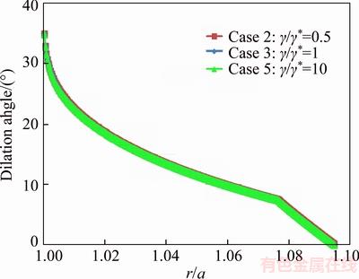
Figure 6 Radial profiles of dilation angle in plastic zone around tunnel under low stress level (r: radial distance; a: tunnel radius)
As shown in Figure 6, dilation angle has decreasing trend from the tunnel wall toward the elastic-plastic boundary, so a constant parameter could not represent variability associated with dilation angle in plastic zone at low stress level. All above findings about dilation behavior in plastic zone around a tunnel excavated in sedimentary rocks can be summarized and presented in Table 3.
Table 3 Dilation angle variations in plastic zone around tunnels excavated in sedimentary rocks
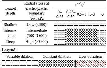
Even though Table 3 shows that dilation angle is constant only under some limited conditions, tunnels usually experience practical situations fulfilling the constant dilation angle condition mentioned in Table 3. Tunnels with high ratio of ��wall/��* represents problematic grounds with high plastic behavior that is far beyond the scope of this study, so tunnels excavated in sedimentary rocks outside the ranges of 0.25�ܦ�wall/��*��3 at intermediate and high stress levels are rare. Furthermore, the study of plastic zone behavior in tunnels under low stress level (overburden) is relatively unimportant because at shallow tunnels structurally controlled failures maybe the prime concern in excavation design [17]. Therefore, it is reasonable to assume that dilative behavior of plastic zone could be represented by constant dilation angle under practical conditions determined in Table 3.
4.2 Crystalline igneous rocks
To study dilation behavior of crystalline igneous rocks, granite rock mass of the Kobbskaret tunnel project [23] in Sweden was selected as a typical situation. Granite rock mass input parameters of the Kobbskaret tunnel project in Sweden are presented in Table 4, where is Poisson ratio, ��0 is isotropic in situ stress, and GSIpeak is the peak value of geological strength index before applying loads. A hypothetical circular tunnel by radius of 2.25 m, under different radial stress levels (high, intermediate, low) at elastic-plastic boundary in granite rock mass with the same property as the Kobbskaret project [23] was analyzed by using the stepwise finite difference approximation analytical method. Like previous section (sedimentary rocks), at each radial stress level, a wide variety of (��wall/��*) was taken into account. All analyzed cases, including all possible conditions of radial stress at the elastic-plastic boundary (��re) and ratio of (��wall/��*), for crystalline igneous rocks can be seen in Table 5.
Table 4 Input data used in analysis of crystalline igneous rock [23]
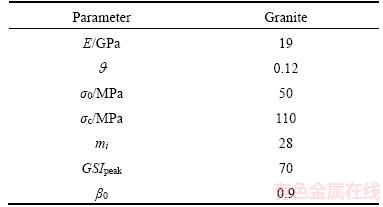
Figure 7 shows radial profiles of dilation angle variations in plastic zone around the tunnel at various ratios of (��wall/��*) at high stress level in accordance with cases 28�C33 in Table 5.
As shown in Figure 7, in case covering ranges of ��wall/��* dilation angle is so variable that it could not be represented by a constant parameter, and dilation behavior depends solely on minimum principal (radial) stress across these ranges.
However, in ranges of 0.05�ܦ�wall/��*��0.75 variability associated with dilation angle in the middle region, the substantial portion of the plastic zone, is insignificant. Although dilation angle in the tunnel wall area and the elastic-plastic boundary region is variable, the tunnel wall and the elastic- plastic boundary regions are extremely thin as illustrated in Figure 7 and have little influence on dilative behavior of the whole plastic zone; Consequently, dilation angle for igneous rocks is approximately constant within these ranges.
In cases including ranges of ��wall/��*��0.75, dilation angle has rising trend from the tunnel wall toward the elastic-plastic boundary region; Therefore, it is unreasonable to assume that dilation angle is constant across these ranges.
In order to better understand dilation angle variations in plastic zone, a graphic representation of dilation angle surface can be created in a mathematical software environment. Intersecting the rock dilation angle surface with the minimum principal stress-shear plastic strain path in a mathematical software environment leads to graphical representation of dilation angle variations in excavation damage zone around tunnel. Figure 8 graphically represents relative position of the minimum principal (radial) stress-shear plastic strain path in respect to the dilation angle surface at different ratios of (��wall/��*) for the plastic zone around the tunnel at high stress level.
In Figure 8, the minimum principal (radial) stress-shear plastic strain path for the plastic zone around the tunnel was determined by using stepwise finite difference approximation analytical method. Figure 8 shows that the experienced shear plastic strain at the tunnel wall is about 0.035 and the radial stress at the elastic-plastic boundary is 7.5 MPa. The dilation angle surfaces at two ratios of (��wall/��*) equal to 0.1 and 1 behave differently; as a result, the more the ratio of shear plastic strain at the tunnel wall to decay rate of the dilation angle (��wall/��*) increases, the more dilation angle surface falls. Since the results at intermediate and low stress levels for crystalline igneous rocks are somewhat similar to the sedimentary rocks results in previous section, it may not be necessary to repeat the results for crystalline igneous rocks at intermediate and low stress levels. All results and findings on igneous rock dilation behavior can be summarized in Table 6. Whereas Table 6 shows that dilation angle is constant only under some limited conditions, tunnels usually are under practical situations that constant dilation angle conditions mentioned in Table 6 are satisfied. Tunnels excavated in igneous rocks outside the ranges of 0.05�ܦ�wall/��*��0.75 in intermediate and high stress levels are very rare. Furthermore, the study of plastic zone behavior in tunnels under low stress level (overburden) is relatively unnecessary because at shallow tunnels structurally controlled failures may be the prime concern in excavation design [17]. Therefore, it is reasonable to assume that dilative behavior of plastic zone could be represented by constant dilation angle under practical conditions determined in Table 6.
Table 5 All possible conditions of radial stress at elastic-plastic boundary (��re) and ratio of (��wall/��*) for crystalline igneous rocks
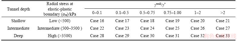
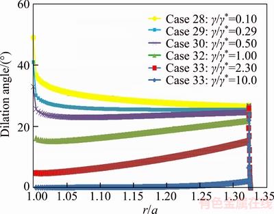
Figure 7 Radial profiles of dilation angle in plastic zone around the tunnel excavated in crystalline igneous rock at high stress level (r: radial distance, a: tunnel radius)
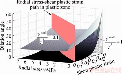
Figure 8 Graphical representation of the minimum principal (radial) stress�Cshear plastic strain path in respect to dilation angle surface at various ratios of (��wall/��*) for plastic zone around tunnel
Table 6 Dilation angle variations in plastic zone around tunnels excavated in crystalline igneous rocks
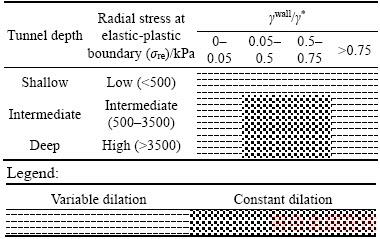
In comparison between Tables 3 and 6, the range of ��wall/��* needed for constant dilation angle in crystalline igneous rocks is more limited than sedimentary rocks. This is in agreement with the general trend that more brittle rocks tend to have lower values of dilation decay parameter (��*) than more ductile (strain-weakening) rocks.
5 Comparing mobilized to constant dilation
According to Tables 3 and 6, under practical conditions, variability associated with dilation angle in plastic zone around tunnels is insignificant, and the middle region of the plastic zone with approximately constant dilation angle plays a prominent role in dilation behavior.
For further investigation of this matter, the radial displacement profile along the plastic zone analyzed based on the mobilized dilation model of WALTON [12] was compared to the radial displacement profile calculated by using the constant dilation angle in the middle region of the plastic zone as shown in Figure 9.
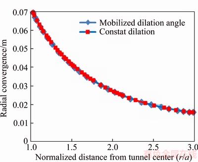
Figure 9 Comparison of mobilized and constant dilation angle for sedimentary rocks at high stress level
According to Figure 9, the radial displacement profile along the plastic zone analyzed based on the mobilized dilation model is practically the same as the radial displacement profile calculated by using constant dilation angle, so under practical conditions aforementioned in Tables 3 and 6 dilation behavior of all over the plastic zone around the tunnel can be approximated to constant dilation angle in the middle region of the plastic zone.
6 Anisotropic in situ stress condition and non-circular tunnel
In preceding section, the study was limited to dilation behavior in plastic zone around a circular tunnel under isotropic in situ stress condition. For further investigation into extending the previous section results to more general situations and the possibility of having constant dilation angle in plastic zone around a tunnel under anisotropic in situ stress condition and non-circular tunnels, the Mine-by test tunnel and the arched tunnel were numerically simulated by using the mobilized (shear plastic strain and confinement-dependent) dilation model in a commercial finite difference software environment.
The Mine-by test tunnel has been a research program conducted by the Atomic Energy of Canada Limited (AECL) from 1983 to1989. Large quantities and anisotropic in situ stress condition in URL project in Canada and registered research field and laboratory data of the project caused that it has been considered as an ideal project for study of excavation damage zone and the failure development in brittle rocks under high and complex stresses in the underground excavations.
6.1 Observed stress state and damage zone in Mine-by test tunnel
The Mine-by is a tunnel with diameter of 3.5 m, length of 46 m and overburden of 420 m. In order to study excavation damage zone around the tunnel as a result of stress redistribution, a mechanical drilling method was used to excavate the Mine-by test tunnel. The host rock of the Mine-by test tunnel consists of Lac du Bonnet granite.
The magnitudes and principal directions of in situ stresses in the Mine-by test tunnel were measured in form of ��1=(60+5) MPa (145��/11��), ��2=(45+4) MPa (54��/8��), ��3=(11+2) MPa (290��/77��) [24, 25]. According to Figure 10, in situ field stresses are applied by 15�� angle with respect to the horizontal and vertical axes.
Due to the Mine-by test tunnel excavation,compressive stresses distributed around the tunnel make V-shaped damage zones created at the roof and floor of the tunnel along the minimum principal stress direction.

Figure 10 Orientation of in situ field stresses in Mine-by test Tunnel [26]
6.2 Numerical simulation of Mine-by test tunnel
6.2.1 Geometry and boundary conditions
For simulation of the Mine-by test tunnel, a numerical model with dimensions of 60 m��60 m was made in a 2D commercial finite difference software environment. As shown in Figure 11, the outer boundaries were placed at a distance of 8 times the Mine-by test tunnel diameter from the tunnel wall, and the numerical model dimensions were selected large enough in order to avoid the boundary effects on the numerical model results.
According to Figure 11, in order to numerically simulate the Mine-by test tunnel at a depth of 420 m, zero velocity fields (fix boundaries) were applied to the bottom and right boundaries of the numerical model in the normal directions. The maximum principal in situ stress ��1=60 MPa was applied to the left boundary by 15�� angle deviation from the horizontal axis, and the minimum principal in situ stress ��3=11 MPa was applied to the top boundary by 15�� angle deviation from the vertical axis. In order to increase accuracy and speed of calculations the dimension of implemented grids decreases, but the grid density increases with distance from the model boundaries toward the tunnel wall as shown in Figure 12.
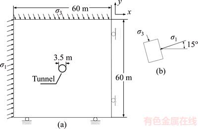
Figure 11 A view of geometry and boundary condition (a) and in situ stress of model (b)
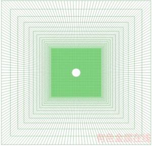
Figure 12 Grids used for numerical simulation of Mine-by test tunnel
A full 2D model of the Mine-by test tunnel (height of 60 m and width of 60 m) was created by using the finite difference code Flac2D. A view of this model is shown in Figure 12 which consists of around 100��300 squared grids.
6.2.2 User-written constitutive model
To study hard rock mass behavior in plasticity framework, the constitutive models such as cohesion weakening friction strengthening (CWFS) [27] and cohesion softening friction hardening (CSFH) [28] have been proposed and shown to be quite successful in replicating observed rock and rock mass behavior. In order to investigate how dilation angle varies in the plastic zone around the Mine-by test tunnel, the Mohr-Coulomb constitutive model was modified via the language imbedded in the commercial finite difference program to take into account CWFS with the mobilized dilation model of WALTON [12], and then the user-written constitutive model with mobilized dilation angle was implemented in numerical simulation. Necessary input parameters of this modified constitutive model for the Lac du Bonnet granite are presented in Table 7.
After creating the initial zoned model and its primary equilibrium under applied in situ field stress conditions, the analysis was done in several steps by the CWFS constitutive model with mobilized dilation angle, and then the circular Mine-by test tunnel was excavated gradually. The instantaneous excavation method makes the greater damage zone and high displacements around the tunnel [26]. In gradual excavation method, instead of immediate removal of tunnel elements, an inner stress boundary at the same level as the in situ stresses was applied to the inner tunnel boundary. According to Figure 13, the applied forces during 2500 steps were gradually reduced, and it reached zero at the final stage.
The stress release at the tunnel boundary by a constant rate leads to gradual excavation of the tunnel
6.2.3 Numerical simulation results
Figure 14 shows the simulated cumulative shear plastic strain (Epss) contours around the Mine-by test tunnel by using CWFS constitutive model with mobilized dilation angle that is able to simulate damage zone at the floor and roof of the Mine-by test tunnel in the finite difference software environment.
As can be seen in Figure 14, while there is no cumulative shear plastic strain (Epss) outside of the damage zone, the cumulative shear plastic strain (Epss) increases gradually from the elastic-plastic boundary at the top of the wedge shaped damage zone to the tunnel wall; therefore, the highest amount of the cumulative shear plastic strain occurs at the tunnel wall. In Figure 14, the damage zone depths at the tunnel roof and floor are estimated to be 52 cm and 47 cm respectively. The transverse extension angles of damage zone at the tunnel roof and floor are estimated to be 70�� and 72�� respectively. Hence, the numerically simulated plastic zone is in good agreement with the observed damage zone in the field. As opposed to the cumulative shear plastic strain, the minimum principal stress (m_str3) increases from the tunnel wall to the elastic-plastic boundary at the top of the wedge shaped damage zone as shown in Figure 15.
Table 7 Input model parameters for numerical simulation [1]
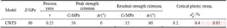

Figure 13 Variation in relaxation rate with calculation step
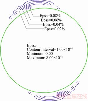
Figure 14 Simulated shear plastic strain (Epss, %) contours inside the damage zone around the Mine-by test tunnel
Figure 16 shows the variations of dilation angle (m_dil) in the plastic zone located at the roof and floor of the Mine-by test tunnel simulated with CWFS and mobilized dilation angle model in the commercial finite difference software environment.
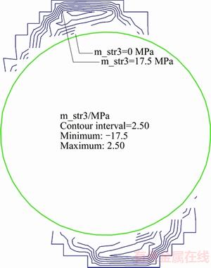
Figure 15 Increase in minimum principal stress (m_str3MPa) from tunnel wall to elastic-plastic boundary
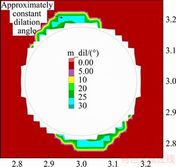
Figure 16 Approximately invariable dilation angle (m_dil) in damage zone around Mine-by test tunnel simulated with mobilized dilation angle model of WALTON [12]
As can be seen in Figure 16, the dilation angle is zero outside of the simulated V shaped damage zone. In spite of the fact that the Mine-by test tunnel was numerically simulated based on the mobilized dilation angle model of WALTON [12] and variable dilation angle would be expected around the simulated tunnel, Figure 16 shows that variability associated with dilation angle around the simulated Mine-by tunnel is insignificant, and dilation angle is approximately constant in the plastic zone. It is due to the governing minimum principal (radial) stress-shear plastic strain path in the plastic zone around the simulated Mine-by test tunnel that resulted in approximately constant dilation angle.
The experienced shear plastic strain at the tunnel wall is about 0.0008 and the minimum principal stress at the elastic-plastic boundary is about 18 MPa, which is high stress level according to Table 5, so the ratio of shear plastic strain at the tunnel wall to decay rate of the dilation angle (��wall/��*) is about 0.16 coinciding with case 29 in Table 5. Because of the fact that the governing minimum principal (radial) stress-shear plastic strain path of the Mine-by test tunnel satisfies the aforementioned practical condition in Table 6, dilation angle variations are insignificant and the dilation angle can be regarded as a constant parameter that is consistent with the simulated dilation in Figure 16.
All plastic models with a non-associated flow rule or post-yield weakening suffer from some forms of bifurcation following material yield [29]. Bifurcation is particularly an issue for brittle materials where sudden cohesion loss can lead to the unpredictable spread of yield.
It has long been understood that bifurcation in frictional materials is both a function of frictional and dilatational properties [30]. Although the relatively high dilatancy values utilized in this study should improve the material stability to some extent, there is still expected to be a notable mesh dependency of the solution obtained [29, 31]. To evaluate how significantly the modelling results vary based on the problem discretization, models were run by using the baseline material parameters and three different grid sizes. In addition to the original grid (~20 cm zone side length), a denser mesh (~15 cm zone side length) and a coarser mesh (~25 cm zone side length) were tested as shown in Figure 17.
According to Figure 17, the mesh sensitivity analysis results show that all three mesh sizes yield approximately similar results. The main result involving the constant dilation angle in the plastic zone around the simulated tunnel despite using the mobilized dilation angle can be seen in all three mesh sizes used especially in the fine grid(Figure 17(a)). Approximately constant dilation angle around the tunnels simulated with the mobilized dilation angle model of WALTON [12] could impose resistance to strain localization and shearing based on SALEHNIA et al [13]. In fact, a constant (nonzero) dilatancy angle could be interpreted as definition of a highly enough dilated material for which there is a resistance to plastic shearing [32] and to the localization [33]. Therefore, high resultant constant dilation could provide a resistance to localization in spite of the impact of the defined cohesion softening to trigger the strain localization [13].
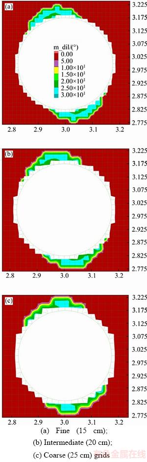
Figure 17 Zoomed views of simulated dilation angle (m_dil��) around the Mine-by:
6.3 A non-circular arched tunnel
The preceding studies were only limited to circular tunnels. For further investigation, a hypothetical arched tunnel with rock mass properties similar to the Mine-by tunnel, input parameters aforementioned in Table 7, under the same anisotropic primary stress condition as the Mine-by tunnel was taken into account. As shown in Figure 18, the size and boundary conditions of the arched tunnel model are the same as the Mine-by tunnel model. The cross section of the arched tunnel is 3.5 m in width and 3.75 m in height. The tunnel is assumed to be constructed by using the full-face excavation method, and the rock support system is ignored. The objective of this study is to investigate whether simulated dilation angle around the arched tunnel, similar to circular tunnels, is approximately constant despite using the mobilized dilation angle in numerical simulation. General and close-up views of the arched tunnel model are presented in Figure 18.
The simulated dilation angle surrounding the arched tunnel modeled by using the mobilized (shear plastic strain and confinement-dependent) dilation model can be seen in Figure 19.
As shown in Figure 19, variability associated with dilation angle around the arched tunnel simulated by using the shear plastic strain and confinement-dependent dilation model is insignificant, and dilation angle around the arched tunnel is approximately constant in spite of using the mobilized dilation model in numerical simulation of the arched tunnel.
7 Conclusions
In this paper, dilation angle variations in plastic zone surrounding circular tunnels under uniform primary stress condition excavated in sedimentary and crystalline igneous rocks were investigated by the stepwise finite difference approximation analytical solution. Under practical engineering conditions, the tunnel wall and the elastic-plastic boundary regions are extremely thin and have little influence on dilative behavior of the whole plastic zone, and dilation angle variations in the middle region, the major portion of the plastic zone, are almost constant; therefore, dilative behavior of all over the plastic zone could be represented by a constant dilation fitted with dilation angle in the middle region of radial dilation angle profile. The second part of this paper devoted to extending the results about dilation angle variation in plastic zone to more general conditions. Further investigation under more general non- uniform in situ stress condition and non-circular tunnel was performed by using the finite difference software to numerically simulate the Mine-by and arched tunnels. Although the Mine-by and arched tunnels were numerically simulated based on the mobilized dilation angle model, and variable dilation angle would be expected around the simulated tunnels, variability associated with dilation angle around the simulated tunnels is insignificant, and dilation angle is approximately constant in the plastic zone. Hence for practical engineering analysis of the tunnels the simplified dilation models with constant dilation angle may be adequate.
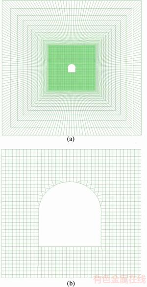
Figure 18 Full finite-difference grid used to model arched tunnel (a) and zoomed view of arched tunnel area (b)

Figure 19 Approximately constant dilation angle (m_dil��) in damage zone resulted from arched tunnel simulation with mobilized dilation angle model of WALTON [12]
Appendix:
Calculation procedure for a circular opening excavated in rock mass with strain softening behavior.
Input data
ri
Radius of tunnel
��0
Hydrostatic stress field
Pi
Internal support pressure
��c
Uniaxial compressive strength
mi
Strength parameter of Hoek & Brown for intact rock
D
Disturbance factor
Poisson ratio
E
Elastic modulus
GSIpeak
Peak value of geological strength index obtained from the field geotechnical quality
Preliminary calculations
1. 
2. 
3. 
4. 
5. 
6. 

7. 
8. 
9. 
10. 
11.  ��
��

12. 
13. 

14. 

15. 
Sequence of calculation for annulus in the plastic zone
1. If the plastic zone around opening divides into n concentric rings, and if
 the plastic zone does not form around opening.
2. If  then
then  and
and  ;
;
If  then ��(i)=��r, and K(i)= K(i�C1)
3. 
4. 
5. 
6. 
7. 

8. 
9. 
 ,
,

10. 
11. 
12. 

13. 
Repeating above calculations n times, then  and
and  The radial displacement at each ring is given by
References
[1] ZHAO X G, CAI M. Influence of plastic shear strain and confinement-dependent rock dilation on rock failure and Displacement near an excavation boundary [J]. International Journal of Rock Mechanics and Mining Sciences, 2010, 47:723�C738. DOI: 10.1016/j.ijrmms.2010.04.003.
[2] KAISER P K, MCCREATH D R, TANNANT D D. Canadian rockburst support handbook [M]. Sudbury: Geomechanics Research Centre/MIRARCO, 1996.
[3] BI J, ZHOU X P, XU X M. Numerical simulation of failure process of rock-like materials subjected to impact loads [J]. Int Geomech J, 2017, 17(3): 04016073. DOI: 10.1061/ (ASCE)GM.1943-5622.0000769.
[4] BI J, ZHOU X P, QIAN Q H. The 3D numerical simulation for the propagation process of multiple pre-existing flaws in rock-like materials subjected to biaxial compressive loads [J]. Rock Mech Rock Eng, 2016, 49(5): 1611�C1627. DOI: 10.1007/s00603-015-0867-y.
[5] ZHOU X P, BI J, QIAN Q H. Numerical simulation of crack growth and coalescence in rock-like materials containing multiple pre-existing flaws [J]. Rock Mech Rock Eng, 2015, 48(3): 1097�C1114. DOI: 10.1007/s00603-014-0627-4.
[6] ZHOU X P, ZHAO Y, QIAN Q H. A novel meshless numerical method for modeling progressive failure processes of slopes [J]. Engineering Geology, 2015, 192: 139�C153. DOI: http://dx.doi.org/10.1016/j.enggeo.2015.04.005.
[7] SILLING S A. Reformulation of elasticity theory for discontinuities and long-range forces [J]. Journal of the Mechanics and Physics of Solids, 2000, 48(1): 175�C209. DOI: https://doi.org/10.1016/S0022-5096(99)00029-0.
[8] ZHOU X P, GU X B, WANG Y T. Numerical simulations of propagation, bifurcation and coalescence of cracks in rocks [J]. International Journal of Rock Mechanics and Mining Sciences, 2015, 80: 241�C254. DOI: http://dx.doi.org/10.1016/ j.ijrmms.2015.09.006.
[9] DETOURNAY E. Elastoplastic model of a deep tunnel for a rock with variable dilatancy [J]. Rock Mech Rock Eng, 1986, 19: 99�C108. DOI: https://doi.org/10.1007/BF01042527.
[10] ALEJANO L R, ALONSO E. Considerations of the dilation angle in rocks and rock masses [J]. International Journal of Rock Mechanics & Mining Sciences, 2005, 42: 481�C507. DOI: 10.1016/j.ijrmms.2005.01.003.
[11] ZHAO X G, CAI M. A mobilized dilation angle model for rocks [J]. International Journal of Rock Mechanics & Mining Sciences, 2010, 47: 368�C384. DOI: 10.1016/j.ijrmms.2009. 12.007.
[12] WALTON G. Improving continuum models for excavations in rock masses under high stress through an enhanced understanding of post-yield dilatancy [D]. Canada: Queen��s University, 2014. https://qspace.library.queensu. ca/handle/ 1974/12655.
[13] SALEHNIA F, COLLIN F, CHARLIER R. On the variable dilatancy angle in rocks around underground galleries [J]. Rock Mech Rock Eng, 2016: 1�C15. DOI: 10.1007/ s00603-016-1126-6.
[14] WALTON G, DIEDRICHS M S. A new model for the dilation of brittle rocks based on laboratory compression test data with separate treatment of dilatancy mobilization and decay [J]. Geotechnical Geology Engineering, 2015, 33: 661�C679. DOI: 10.1007/s10706-015-9849-9.
[15] WALTON G, DIEDERICHS M S. Dilation and post-peak behaviour inputs for practical engineering analysis [J]. Geotechnical Geology Engineering, 2015, 33: 15�C34. DOI: 10.1007/s10706-014-9816-x.
[16] VERMEE P A, DE BORST R. Non-associated plasticity for soils, concrete and rock [J]. Heron, 1984, 29(3): 1�C64. https://repository.tudelft.nl/islandora/object/uuid:4ee188ab-8ce0-4df3-adf5-9010ebfaabf0?collection=research.
[17] BRADY B H G, BROWN E T. Rock Mechanics for Underground Mining [M]. London: Chapman & Hall, 1993.
[18] EDWIN T, BROWN M, JOHN W, BRANKO B, LADANYI F, HOEK E. Ground response curves for rock tunnels [J]. Journal of Geotechnical Engineering, 1983, 109: 15�C39. https://ascelibrary.org/doi/abs/10.1061/%28ASCE%290733-9410%281983%29109%3A1%2815%29.
[19] ALEJANO L R, ALONSO E, RODRIGUEZ-DONO A, FERNANDEZ-MANIN G. Application of the Convergence- confinement Method to Tunnels in Rock Masses Exhibiting Hoek�CBrown Strain-softening Behaviour [J]. International Journal of Rock Mechanics And Mining Sciences, 2010, 47: 150�C160. DOI: 10.1016/j.ijrmms.2009.07.008.
[20] LEE Y K, PIETRUSZCZAK S. A new numerical procedure for elasto-plastic analysis of acircular opening excavated in astrain-softening rock mass [J]. Tunnelling and Underground Space Technology, 2008, 23: 588�C599. DOI: 10.1016/j.tust.2007.11.002.
[21] KATEBIAN E, MOLLADAVOODI H. Practical ground response curve considering post peak rock mass behavior [J]. European Journal of Environmental and Civil Engineering. 2017, 21(1): 1�C23. DOI: http://dx.doi.org/10.1080/19648189. 2015. 1090928.
[22] FARROKH E, ROSTAMI J. Correlation of tunnel convergence with TBM operational parameters and chip size in the Ghomroud tunnel, Iran [J]. Tunnelingand Underground Space Technology, 2008, 23: 700�C710. DOI: 10.1016/j.tust.2008.01.005.
[23] EDELBRO C. Different approaches for simulating brittle failure in two hard rock mass cases: A parametric study [J]. Rock Mech Rock Eng, 2010, 43: 151�C165. DOI: 10.1007/s00603-008-0025-x.
[24] MARTIN C D. Strength of massive Lac du Bonnet granite around underground openings [D]. Winnipeg: University of Manitoba, 1993.
[25] MARTIN C D, READ R S. AECL��s Mine-by experiment: A test tunnel in brittle rock [C]// Proceedings of the 2nd North American Rock Mechanics. Montreal: A. A. Balkema, 1997.
[26] ZHAO X G, CAIM, CAI M. Considerations of rock dilation on modeling failure and deformation of hard rocks��A case study of the mine-by test tunnel in Canada [J]. Journal of Rock Mechanics and Geotechnical Engineering, 2010, 2(4): 338�C349. DOI: 10.3724/SP.J.1235.2010.00338.
[27] HAJIABDOLMAJID V, KAISER P K, MARTIN C D. Modelling brittle failure of rock [J]. International Journal of Rock Mechanics & Mining Sciences, 2002, 39: 731�C741. DOI: https://doi.org/10.1016/S1365-1609(02)00051-5.
[28] EDELBRO C. Numerical modelling of observed fallouts in hard rock masses usingan instantaneous cohesion-softening friction-hardening model [J]. Tunneling and Underground Space Technology, 2010, 24, 398�C409. DOI: 10.1016/j.tust. 2008. 11.004.
[29] DE BORST R. Bifurcations in finite element models with a non-associated flow law [J]. International Journal of Numerical and Analytical Methods in Geomechanics, 1988, 12: 99�C116. DOI: 10.1002/nag.1610120107.
[30] VARDOULAKIS I. Shear band inclination and shear modulus of sand in biaxial tests [J]. International Journal of Numerical and Analytical Methods in Geomechanics, 1980, 4: 103�C119. DOI: 10.1002/nag.1610040202.
[31] HOBBS B E, ORD A. Numerical simulation of shear band formation in a frictional-dilatational material [J]. Ingenieur- Archiv, 1989, 59: 209�C220. https://link.springer.com/article/ 10.1007/BF00532251.
[32] KIRKEBf S. A numerical study of excavations in low permeable soils [D]. Trondheim: University of Trondheim, 1994.
[33] BERNIER F, LI X, BASTIAENS W, ORTIZ L, VAN GEET M, WOUTERS L, FRIEG B, BLU ��MLING P, DESRUES J, VIAGGIANI G. Fracturesand self-healing within the excavation disturbed zone in clays (selfrac) [R]. Final report to EC (Project FIKW-CT2001-00182). 2007, EUR, 22585.
(Edited by HE Yun-bin)
���ĵ���
�ڳ�����������ݲ�������ʯ�������������ݽǵı仯
ժҪ�����ݽ���������ֵģ����һ����Ҫ�IJ�������Ȼ��������ģ�ͱ������ݲ����DZ�������Լ���й��Ҿ��ܼ���Ӧ�䣬�����ó������ݲ����������͵��¿�������ֵģ�⣬��ʵ��Ӧ���п��Եõ���������Ľ�������о�ּ�ڲ���Ϊʲô��ʵ���Һ���������У����ݽ�Ϊ����������ʵ���������͵��²��ڵ���ֵģ������п����ó�������ģ�⡣�о����������������ݽǵı仯��������ھ��о���ԭλӦ������Բ�����������ÿ���Ӧ������������Ϊ���ݶ�����ֽ��ƽ������о����ڲ�ͬ�����£��ƶ����ݽ���������Χ�������ı仯���ɡ��ڱ��о�ȷ����ʵ�������£�������Χ������ȫ����������Ϊ���Խ���Ϊ�������в��ĺ㶨���ݽǡ����⣬�Ƚ����ƶ����ݽ�ģ�ͺͶ����ݽ�ģ�͵�������λ�ơ��������������������AECL�����ô�ԭ��������˾���Ŀ�ɽ������������������������ֵģ�⣬�ԷǾ���Ӧ�������ͷ�Բ�����������˽�һ���о�����Ȼ���ƶ����ݽ�ģ�͵Ļ����϶Կ�ɽ�����������������ֵģ�⣬��ģ���ɽ�����������Χ�����ݽDZ仯�����ԣ����������ݽǽ��ƺ㶨��
�ؼ��ʣ����ݣ������Ϊ����������Ӧ������
Received date: 2017-09-18; Accepted date: 2018-01-22
Corresponding author: Hamed MOLLADAVOODI, PhD, Assistant Professor; Tel: +98�C21�C64542908; E-mail: davoodi@aut.ac.ir; ORCID: 0000-0003-1988-1568

