J. Cent. South Univ. Technol. (2010) 17: 142-149
DOI: 10.1007/s11771-010-0023-5 
Fatigue properties of special kind of reinforced concrete composite beams
HU Tie-ming(胡铁明)1, 2, HUANG Cheng-kui(黄承逵)1, CHEN Xiao-feng(陈小锋)1
1. State Key Laboratory of Coastal and Offshore Engineering, Dalian University of Technology,
Dalian 116024, China;
2. School of Architectural and Civil Engineering, Shenyang University, Shenyang 110044, China
? Central South University Press and Springer-Verlag Berlin Heidelberg 2010
Abstract: The special reinforced concrete composite beam consists of a steel fiber reinforced self-stressing concrete composite layer and a reinforced concrete T-beam, and constructional bars are set up at their bonding interface. Fatigue properties of the composite beam under the action of negative moment were experimentally studied. Through inverted loading mode the load-bearing state of a composite beam was simulated under the action of negative moment. With the ratios of constructional bars being 0, 0.082% and 0.164% respectively as parameters, the effects of constructional bars on the properties of composite beam, such as fatigue life, crack propagation, rigidity loss as well as damage behavior of bonding interface, were studied. The mechanism of the constructional bars on the fatigue properties of the composite beams and the restriction mechanism of crack widths and rigidity loss were analyzed. The test results show that the constructional bars can enhance the shear resistance of the bonding interface between composite layer and old concrete beam and restrict expanding of steel fiber reinforced self-stressing concrete, which are beneficial to synergistic action of composite layer and old concrete beam, to reducing the stress amplitude of bars and the crack width of composite layer, and to increasing the durability and fatigue life of the composite beam.
Key words: steel fiber reinforced self-stressing concrete; composite beam; constructional bar; bonding interface; fatigue
1 Introduction
In the strengthening and repairing work of a continuous girder concrete bridge, the action of tensile stress in the sections under the action of negative moment could cause more cracks in structural surface, and when the propagation of crack width reached a certain extent, the decrease of serviceability and durability of bridge structures would occur. If the steel fiber reinforced self-stressing concrete (SFRSC) with relatively high tensile strength and crack resistance was placed into the composite layer to strengthen the negative moment zone of continuous girder bridges, the development of crack width of the layer surface could be effectively decreased, and the serviceability and durability of structures could be enhanced [1-3]. Presently, SFRSC is mainly used in pressure pipes, but its use in strengthening and repairing work of concrete structure is still in preliminary research stage. The fatigue property of the composite beam with SFRSC layer and old concrete beam was studied by CHEN [4], and the test beams were invertedly loaded and simply supported under the action of negative moment. Through comparisons with ordinary concrete and steel fiber reinforced concrete, it was found that SFRSC effectively reduced the development of crack width of structural surface and enhanced fatigue resistance of structures.
However, for the bonding interface between new and old concrete, because it is in complex stress state, the principal tensile stress makes it crack, particularly when it is in tensile zone. According to current research results, two methods to effectively enhance shear resistance of the bonding interface are available: one is that the old concrete surface is made into coarse bonding interface, the other is that constructional bars are set up on the basis of coarse bonding interface. With respect to the studies of the former, different bonding means were mainly adopted to enhance the combining property between new and old concrete to achieve the purpose of shear resistance of bonding interface [5-6]. With respect to the studies of the latter, the shear resisting effect of the constructional bars on the bonding interface through static shear tests of new and old concrete combined specimens was mainly determined [7-8]. Considering the contribution of constructional bars to the shear resistance of the bonding interface, the corresponding calculation is stipulated in the code ACI318M―05, i.e., when the coarseness of bonding interface reaches 6 mm, according to different ratios of constructional bars, the shear capacity of the bonding interface with constructional bars will be higher than that without constructional bars, which can reach 6.4 times.
Generally, up to now the studies of the shear resisting property of bonding interface with constructional bars are still only confined to static experiment, theoretical analysis and numerical simulation, but the research literatures on the effect of constructional bars on the fatigue property of bonding interface of the composite beam have been not published. For this reason, in this work the experimental study of SFRSC composite beams was carried out under the action of negative moment, and the effects of constructional bars on the fatigue property of bonding interface and composite beam were investigated by taking the constructional bars ratio as a variable.
2 General situation of test
2.1 Specimen design
Test specimens were designed and prepared according to the technical characteristics of strengthening for transformation from old bridge’s simply-supported system to continuous system and in accordance with the similarity theory for section rigidity, as shown in Fig.1. At the bonding interface constructional bars named as S0 were placed. The bars acted the following roles: (1) decreasing the shear stress of the bonding interface between new and old concrete, (2) restraining normal micro-expansion of SFRSC at the bonding interface to make normal compressive stress action so as to enhance the shear resistance of the bonding interface. The composite beams were numbered respectively by C0 to C3. For beams C0, C1 and C2, constructional bars S0 were placed at the bonding interface, the bars were shaped Π and their spaces were 400, 200 and 400 mm, respectively; for beam C3, constructional bar was not placed at the bonding interface. The section depth of specimens was 360 mm, and the span was 2 880 mm, with the depth-to-span ratio of 1?8. The depth of old RC beam was 310 mm and that of composite layer was 50 mm. Bars S1 were tensile rebars in the composite layer, bars S2 were tensile rebars in old beam, bars S3 were compressive bars in the web of the old beam, and bars S4 were stirrups with a space of 100 mm. In order to make composite layer free of the restraints of vertical loading points at the two ends, a gap of 10 mm was set to separate it from the loading points at each end.
The composite beams were manufactured in two steps. Firstly an old RC beam was cast and cured in natural environment for 90 d, and then the surface of old RC beams was roughened with a roughness of 6.8-7.4 mm. Reinforcements of composite layer were tied and SFRSC was poured.
2.2 Materials of specimen
The hot-rolled steel bars of HRB335 and HPB235 produced by Tonghua Iron & Steel Group Co., Ltd. were adopted respectively for longitudinal bars and stirrups. Diameters of longitudinal bars are shown in Fig.1 and diameter of stirrup is 6 mm. The cold rolled ribbed steel bars of CRB550 with a diameter of 5 mm produced by Dalian Cold-rolled Ribbed Steel Wires Factory of China were adopted for constructional bars. The grade of other spreading and frame bars was the same as that of stirrup. The results of tensile tests of all reinforcements are shown in Table 1.
Table 1 Results of tensile tests of reinforcements
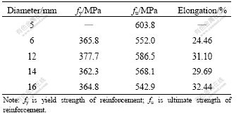
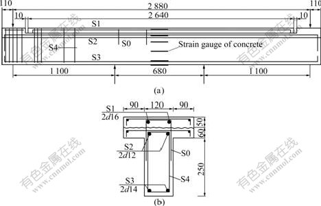
Fig.1 Measuring point arrangement (a) and reinforcement (b) of composite beams (Unit: mm)
The old concrete beams were cast by commercial concrete with strength grade of C40, and the cubic compressive strength and elastic modulus at 28 d age were 47.6 MPa and 33.6 GPa, respectively.
The new concrete layers were cast with SFRSC possessed strength grade of C45 and target self-stress of 4.0 MPa. The self-stressing cement was produced by Shijiazhuang Special Cement Plant China, the steel fiber of type HE0.75/35 cut with steel wire was produced by Arcelor Iron & Steel Group and the aggregates were the crushed limestone and medium sand exploited in Dalian’s suburban. The mass proportion of the concrete was as follows: m(cement)?m(water)?m(sand)?m(crushed stone)=550?250?609?913, with 1.0% of steel fiber by volume. The cubic compressive strength and elastic modulus at 28 d age were 55.9 MPa and 32.5 GPa, respectively.
2.3 Experimental scheme
According to the loading condition of fatigue test, the load bearing character of composite beam in negative moment zone was simulated by inverting the composite beam and applying four-point bending load plan. At sliding hinged support ends, two sheets of PTFE plates of 2 mm-thick were stuck under the supports with grease applied between them as lubricant, so that the supports were fully free for horizontal displacement and rotation.
Fatigue loads were constant amplitude loads with frequency from 1 to 4 Hz. In order to accurately determine the fatigue test load, at first static destructive test was performed on beam C0 to get cracking moment Mcr and ultimate moment Mu. The upper limit of moment Mmax of the beams under fatigue tests was equal to 0.75 times of that of static ultimate moment Mu, and the low limit Mmin was equal to 0.1Mu.
For the fatigue test, firstly, three times of static loading-unloading cycles should be done, and then the fatigue loading test with constant amplitude was conducted. In static loading cycles, the load from zero to the maximum Pmax was divided into five levels, and one level should be loaded at the minimum load Pmin; unloading levels were the same as the loading levels. When the first loading was conducted, the load levels should be finely divided prior to occurring of crack so as to accurately determine the cracking load. The test data such as crack widths, settlements of support, mid-span deflection and ultrasonic velocity at two sides of the bonding interface should be acquired. During fatigue test the fatigue loads should be suspended respectively when the numbers of cycles were equal to 1×10³, 1×10⁴, 5×10⁴, 1×10⁵ and 2×10⁵ as well as fatigue failure of the specimen approached. Then a static test under load from Mmin to Mmax should be conducted and the test data should be gathered. After a static test was finished the fatigue test would be continued. To prevent sudden fatigue failure of composite beam, the deflection limit was set to control the process of fatigue tests, so as to gather relevant test data immediately when the sign of fatigue failure (deflection control was out of limit) occurred.
An electro-hydraulic-servo fatigue test machine manufactured by America’s MTS Systems Corporation was adopted as the loading equipment. The load capacity and stroke range of the actuator were ±250 kN and ±75 mm, respectively. A dynamic data acquisition system for test data such as strains of bars and concrete, load, deflection and displacement, was adopted.
3 Results and discussion
3.1 Static test
As for static destructive test of beam C0, the first crack occurred on the flange of composite beam when the load reached 60 kN, and vertically crossed the bonding interface, with a crack height of 105 mm, and the widths of cracks at the beam side faces corresponding centers of rebars S1 and S2 were basically the same. Along with the increase of load the number of cracks increased, the crack width grew, the mid-span deflection increased, then the stress of rebar S1 increased rapidly and exceeded stress of rebar S2 until rebar S1 yielded. After rebar S1 yielded, a main crack formed at mid- span, with a sharp increase of crack width and a rapid growth of mid-span deflection until loss of bearing capacity of the composite beam. During test process from beginning to end, no indication of failure occurred for the bonding interface, and the longitudinal bars in composite layer were in a good load-bearing state, showing good bonding property of the layer and old concrete beam. The failure behavior of the composite beam was that rebar S1 in pure bending section yielded at first; then rebar S2 yielded, width of major crack and deflection grew remarkably; finally partial concrete in pressure zone collapsed, the ultimate bearing capacity Pu reached 176.1 kN and the ultimate bending moment Mu reached 96.86 kN・m.
3.2 Fatigue test
In the process of fatigue test, the shear resisting property of bonding interface of beam C3 decreased because there were no constructional bars placed at the bonding interface, and some horizontal cracks occurred in the initial stage of fatigue loading and gradually extended with the increase of loading cycles. The bonding interfaces of beams C1 and C2 showed relatively strong bonding property and shear resistance because of the effect of constructional bars, and only few horizontal cracks along the bonding interface occurred in the full process of loading cycles. All the final failures of beams C1-C3 were shown as fatigue breakage of rebar S1 in composite layer and thereupon tearing rupture of partial bonding interface. The fatigue test results are shown in Table 2.
3.2.1 Shear stress of bonding interface and rebar stress
Under fatigue load, the fatigue life of structure depends on the fatigue damage of materials of the composite beams. Along with the increase of fatigue cycles, material’s damage factor Dn (0≤Dn≤1) will continuously increase, i.e., Dn of bonding interface, rebar and SFRSC grows along with the increase of fatigue cycles. At n of cycles, the amplitude of the shear stress  at the bonding interface grows to
  from initial shear stress amplitude (?τ), and the stress amplitude of rebar
  grows to
  from initial rebar stress amplitude of ?σ. When damage of bonding interface, rebar and steel fiber reinforce self-stressing concrete reaches a certain degree, which results in one of them reaching its fatigue limit, fatigue breakage of the composite beam will then occur immediately.
Under the action of repetitive shear stress for a lot of times, the internal damage gradually accumulates at the bonding interface, and the relative deformation between new and old concrete increases unceasingly, which results in the increase of average shear stress of the bonding interface, i.e., the degradation of shear resisting property of bonding interface. If the constructional bars are placed on the bonding interface to share part of shear stress so as to reduce the shear stress of bonding interface between new and old concretes, the fatigue damage of bonding interface can be decreased effectively to some extent. The sketch map for damage development of bonding interface under the action of fatigue shear stress is shown in Fig.2.
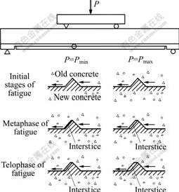
Fig.2 Damage development of bonding interface under action of fatigue shear stress
Through comparison among composite beams of C1-C3, it can be found that the fatigue life (N) is prolonged with the increase of the ratio of constructional bars (ρsv), and the variation in the amplitude of stress of rebars S1 and S2, namely  correlates with ρsv, as shown in Fig.3 and Fig.4. The bonding interface of beam C3 suffers relatively serious damage under the action of fatigue shear stress, leading to a sharp increase of
  of rebars S1 and S2. The fatigue damages of the bonding interfaces of beams C1 and C2 are relatively small, and the composite layer and old concrete beam are capable of synergistic working; of rebars S1 and S2 increases slowly, and the growing rate of of beam C1 is relatively small. The test results indicate that the constructional bars can enhance the synergistic property of the composite layer and old concrete beam, and the fatigue life of the composite beam is prolonged to some extent with the increase of ρsv.
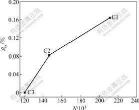
Fig.3 Relation curve for ratio of constructional bars (ρsv) and fatigue life (N)
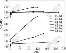
Fig.4 Relation curves for  of rebars S1 and S2 and fatigue cycle (n)
3.2.2 Crack width
Steel fiber and reinforcements in the composite layer restrain expanding of self-stressing concrete, which makes the pre-compressing stress in the concrete and pre-tensioned stress in reinforcements occur when the self-stressing concrete hardens. Therefore, the anti- tension ability and crack resistance of the composite beam are significantly increased. It is thus clear that, under the action of load, the stress state of composite layer is similar to that of tensile edge of partially pre-stressed concrete beam, both states of stress respectively undergo four stages as σ<0, σ=0, σcr≥σ>0 and σ>σcr, where σ is tensile stress of concrete, and σcr is the first crack stress of concrete.
The relation curves for crack width (wmax) and fatigue cycle (n) are shown in Fig.5. The development of the maximum crack width (wmax) of beams C1 and C2 under fatigue load cycles is divided into three stages: initial development, stable extending and failure. The wmax of beam C3 develops at a higher speed during fatigue loading and is always in the stage of rapid development. Under fatigue loading from 1×10³ to 1×10⁵ cycles, wmax of beam C3 is increased by 300%, while wmax of beams C1 and C2 is only increased by 25% and 70%, respectively. The test results indicate that the reinforcing effect of the constructional bars on the bonding interface is effective and the crack development of the composite beams is effectively controlled. When wmax reaches 0.3 mm, beam C3 without constructional bars undergoes about 5×10⁴ fatigue cycles, while beams C2 and C1 undergo about 1.3×10⁵ and 2×10⁵ fatigue cycles, respectively. According to Ref. [9], the formula for calculation of the maximum crack width considering long-term action effect is as follows:
 (1)
(1)
where C1, C2 and C3 are the influencing coefficients for working state of the element, the long-term action effect and face shape of rebar, respectively, for the test C1=1.0, C2=1.5 and C3=1.0; σss is the tensile stress of longitudinal rebar; Es is the elastic modulus of steel, for the test σss=300 MPa (at Mmax) and Es=200 GPa; d is the diameter of longitudinal tensile reinforcements; ρ is the ratio of longitudinal tensile reinforcements. Thus by Eq.(1) the calculated value of wmax is equal to 0.17 mm, which is slightly higher than the observed value of the maximum crack width (0.16 mm) of beam C1 in the last stage of fatigue test. Thus it can be seen that the calculated value of wmax quite agrees with the experimental value.
3.2.3 Rigidity loss
The change of mid-span curvature and the increment of mid-span deflection of the composite beam are adopted to analyze the extent of rigidity loss of composite beam [10-13]. Because the mid-span deflection is directly proportional to mid-span curvature, the mid-span deflection will grow when the mid-span curvature increases. The mid-span curvature 1/ρ can be determined by sum of strains of rebar and concrete at the mid-span section of the composite beam divided by effective depth h0 of the section:
 (2)
(2)
where  is the average strain of compressive concrete extreme edge, which can be approximately set to be equal to εc of the maximum strain of concrete in pure bending zone;
  is the average tensile strain of reinforcements, which can be calculated by
  here
here  is the tensile strain of reinforcements, ψ is the coefficient of uneven strain for tensile bars between cracks,
  here ρte is the ratio of rebar to the tensile effective sectional area of concrete, ft is the tensile strength of concrete and σs is the tensile stress of longitudinal reinforcements. Substituting values respectively for εc, ψ and εs in Eq.(2), the following equation can be obtained:
 (3)
(3)
Table 2 Results of fatigue test
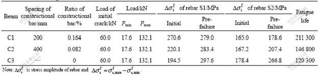
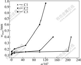
Fig.5 Relation curves for crack width (wmax) and fatigue cycle (n)
It can be seen from Eq.(3) that the accumulation of fatigue damage of rebar and concrete strains can cause the increase of the curvature of section and the growth the mid-span deflection successively. When the constructional bars are adopted to enhance the shear resisting property of bonding interface, the bonding property of the composite layer and old concrete beam will be enhanced, which enables SFRSC to bring its bend resistance role into full play, and thereby to reduce the accumulation of fatigue damage strains of rebar and concrete in the composite beam.
It can be seen from Fig.4 and Table 3 that with increasing fatigue cycles the strains of rebar S2 in beams C1, C2 and C3 increase successively, so does the compression strain of extreme edge concrete at mid-span section 
Table 3 Fatigue strain ( , 10-6) of extreme edge concrete at mid- span section
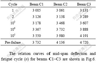
The relation curves of mid-span deflection and fatigue cycle (n) for beams C1-C3 are shown in Fig.6. All the variations in mid-span deflection of the beams exhibit three-stage of fatigue property, and the growing rate of deflection increases with the decrease of ρsv. Within 1×10³ cycles, the mid-span deflection increases quickly and the rigidity of the composite beam remarkably decreases; from 1×10³ cycles to the foreboding of fatigue failure, the deflections of beams C1 and C2 increase slowly, and the rigidity of composite beams is in the stage of stable decrease, but the deflection of beam C3 still grows quickly and the corresponding rigidity loss is aggravated. After the foreboding of fatigue failure, all mid-span deflections of the three beams undergo a sharp increase, along with a quick increase of rigidity loss, until the fatigue failure of composite beam. In the developmental stage of rigidity loss for 1×10³-1×10⁵ cycles, the deflection of beam C3 increases from 7.43 to 9.37 mm, with a growing rate of about 26.1% and a rigidity loss increase by about 20.7%; while the rigidity loss of beams C1 and C2 increases by 5.5% and 7.1%, respectively. The test results indicate that the rigidity loss of composite beams increases with the decrease of ρsv, and in the above- mentioned fatigue cycles the rigidity loss of beam C3 increases by 15.2% compared with that of beam C1.
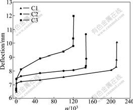
Fig.6 Relation curves for mid-span deflection and fatigue cycle (n)
3.2.4 Bonding interface damage
The extent of bonding interface damage directly affects the bearing capacity and serviceability of composite beam. In the fatigue test the ultrasonic detection was adopted to analyze the damage behavior of the bonding interface because of the action of fatigue load [14-17].
When data acquisition was carried out, two ultrasonic detectors were respectively placed at two sides of the bonding interface; one was placed on flange at original mid-span point, the other was placed at the position under the opposite flange being 500 mm away from the original point of mid-span. Detections were conducted under the states of Mmax and Mmin at 1,1×10³, 1×10⁴ and 1×10⁵ cycles and foreboding of fatigue failure of the composite beams. Fig.7 shows the relationship between the ultrasonic velocity (v) and the fatigue cycle (n). It can be seen that the initial ultrasonic velocities are slightly different from each other, which are caused by original defects existing to different extents during the process of making composite beams, which does not hinder the evaluation of fatigue damage on the bonding interface. Along with the increase of the fatigue cycles, the ultrasonic velocities for the bonding interfaces of beams C2 and C3 under states of Mmax and Mmin show normal three-stage character, i.e., the damage development in initial stage of fatigue, stable damage in intermediate stage of fatigue and sharply increased damage in later stage of fatigue; while for beam C1 there are only initial development stage of damage and later stable stage of damage. The test results indicate that the extent of fatigue damage of the bonding interface decreases with the increase of ρsv, and when ρsv=0.164% (for beam C1), the bonding interface shows two-stage damage property, with the stable bonding performance of the composite layer and the old concrete beam.
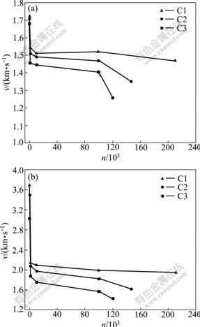
Fig.7 Relation curves for ultrasonic velocity (v) through bonding interface and fatigue cycle (n): (a) M=Mmax; (b) M=Mmin
4 Conclusions
(1) The constructional bars enable steel fiber reinforce self-stressing concrete and the old concrete beam to work in a synergistic way, and the fatigue life of composite beam is prolonged with the increase of the ratio of the constructional bars.
(2) The reinforcing effect of the constructional bars on the bonding interface enables steel fiber reinforce self-stressing concrete to bring the anti-crack properties into full play, so as to reduce the development of structural surface cracks and effectively enhance the serviceability and durability of negative moment zone of the structure.
(3) The rigidity loss of composite beam increases with the increase of fatigue cycles, and decreases with the increase of the constructional bars at the bonding interface. Under the action of fatigue load of Mmax= 0.75Mu and Mmin=0.1Mu, from 1×10³-1×10⁵ of fatigue cycles, the rigidity loss of beam C3 without constructional bars reaches 20.7%, while that of beam C1with constructional bars only reaches 5.5%.
(4) The extent of fatigue damage of the composite beam and bonding interface has the tendency to decrease with the increase of constructional bars ratio ρsv. But, under the condition of the same rebar ratio ρsv, the change in diameter and spacing of constructional bars will cause the change in fatigue property of composite beam to some extent. Optimizing the ratio, diameter as well as spacing of constructional bars at the bonding interface and adapting them to engineering application still need further researches.
References
[1] HE Hua-nan, HUANG Cheng-kui. Calculation of tensile strength of self-stressing concrete reinforced with steel bar and fiber [J]. Journal of Building Materials, 2002, 5(1): 32-36. (in Chinese)
[2] DAI Jian-guo. Calculation theory of deformation and self-stressing of self-stressing concrete reinforced with steel bar and fiber [D]. Dalian: Dalian University of Technology, 2000. (in Chinese)
[3] HE Hua-nan, HUANG Cheng-kui. Experimental research on stress- strain full curve of steel fiber reinforced self-stressing concrete in tension [J]. Journal of Dalian University of Technology, 2004, 44(5): 710-713. (in Chinese)
[4] CHEN Xiao-feng. Experimental study on fatigue behavior of the beams strengthened by steel fiber reinforced self-stressing concrete layer [D]. Dalian: Dalian University of Technology, 2008. (in Chinese)
[5] MOMAYEZ A, EHSANI M R, RAMEZANIANPOUR A A, RAJAIE H. Comparison of methods for evaluating bond strength between concrete substrate and repair materials [J]. Cement and Concrete Research, 2005, 35(4): 748-757.
[6] YU Jian-cheng, ZUO Wen-sheng, CHENG Zhu-hui, TONG Je, HUANG Wei. Research on combined interface of laminated concrete plate-girder bridge [J]. Journal of Southeast University: Natural Science Edition, 2007, 37(2): 222-228. (in Chinese)
[7] WANG Zhen-ling, LIN Yong-jun, QIAN Yong-jiu. Experimental research on shear properties of new-to-old concrete interface [J]. Journal of Southwest Jiaotong University, 2005, 40(5): 600-604. (in Chinese)
[8] CHEN Feng, ZHENG Jian-lan. Experimental research on direct shear behavior of adhesion of self-compacting concrete on existing concrete [J]. Journal of Building Structures, 2007, 28(1): 59-63. (in Chinese)
[9] China Communication Construction Company. Highway Consultants CO., Ltd. JTG D62-2004. Code for design of highway reinforced concrete and prestressed concrete bridges and culverts [S]. Beijing: China Communications Press, 2004. (in Chinese)
[10] QIU Wen-liang, JIANG Meng. Nonlinear finite element analysis of steel-concrete composite beams [J]. Journal of Harbin Institute of Technology: New Series, 2005, 12(5): 581-586.
[11] KELLER T, GüRTLE H. Composite action and adhesive bond between fiber-reinforced polymer bridge decks and main girders [J]. Journal of Composites for Construction, 2005, 9(4): 360-368.
[12] SUTHIWARAPIRAK P, MATSUMOTO T. Fatigue analysis of RC slabs and repaired RC slabs based on crack bridging degradation concept [J]. Journal of Structural Engineering, 2006, 132(6): 939- 948.
[13] LIU Xiao-jie, YU Zhi-wu, JIANG Li-zhong. Long term behavior of self-compacting reinforced concrete beams [J]. Journal of Central South University of Technology, 2008, 15(3): 423-428.
[14] MIRMIRAN A, WEI Y M. Damage assessment of FRP-encased concrete using ultrasonic pulse velocity [J]. Journal of Engineering Mechanics, 2001, 127(2): 126-135.
[15] DILEK U. Ultrasonic pulse velocity in nondestructive evaluation of low quality and damaged concrete and masonry construction [J]. Journal of Performance of Constructed Facilities, 2007, 21(5): 337-344.
[16] ZHAO Shun-bo, YANG Xiao-ming, LI Xiao-ke, GAO Run-dong. Experimental study on deterioration of concrete strength under different sub-high temperature cycles [J]. Journal of Wuhan University of Technology: Materials Science Edition, 2006, 21(S1): 53-57.
[17] CHEN Yue-shun, WEI Jun, ZHAO Xiao-long. Description of concrete durability damage process [J]. Wuhan University Journal of Natural Sciences, 2006, 11(3): 653-656.
Foundation item: Project(50578027) supported by the National Natural Science Foundation of China
Received date: 2009-03-30; Accepted date: 2009-06-28
Corresponding author: HU Tie-ming, Doctoral candidate, Associate Professor; Tel: +86-24-85891366; E-mail: hu_tm@163.com
(Edited by CHEN Wei-ping)

