网络首发时间: 2017-06-30 11:22
稀有金属 2018,42(10),1077-1083 DOI:10.13373/j.cnki.cjrm.xy17040007
FEC作为高压电解液溶剂对富锂材料性能的影响
赵金玲 王建涛 常增花 卢世刚
北京有色金属研究总院国联汽车动力电池研究院有限责任公司
摘 要:
在传统碳酸酯电解液中添加氟代碳酸乙烯酯 (FEC) 可提高电解液的氧化分解电位, 从而在高于4. 5 V (vs. Li/Li+) 电压下减少电解液溶剂的分解。用FEC部分或全部取代传统电解液中的碳酸乙烯酯 (EC) 溶剂, 研究4. 7 V (vs. Li/Li+) 高电压下FEC对Li (1. 18) Mn (0. 52) Co (0. 15) Ni (0. 15) O2电化学性能的影响。结果表明, FEC的加入提高了Li (1. 18) Mn (0. 52) Co (0. 15) Ni (0. 15) O2电极的首次放电比容量及循环性能, 且循环稳定性随FEC量的增加而变高, EC被FEC (33. 33%, 质量分数) 全部取代EC时电化学性能最佳;循环100周时, FEC为33. 33%的电解液中Li (1. 18) Mn (0. 52) Co (0. 15) Ni (0. 15) O2电极的比容量为200. 5 mAh・g-1, 容量保持率为85. 72%, 而传统电解液中Li (1. 18) Mn (0. 52) Co (0. 15) Ni (0. 15) O2电极的比容量在60周时衰减至115. 0 mAh・g-1, 容量保持率仅为49. 89%。d Q/d V曲线表明, 随FEC取代量的增加, 循环过程中产生的电化学极化越小。X射线衍射 (XRD) 结果表明, 在循环过程中, 由于FEC的加入缓减了Li (1. 18) Mn (0. 52) Co (0. 15) Ni (0. 15) O2结构的变化, 且FEC全部取代EC时效果最佳。
关键词:
锂离子电池;高压电解液;富锂锰基材料;氟代碳酸乙烯酯;
中图分类号: TM912
作者简介:赵金玲 (1990-) , 女, 山西朔州人, 硕士研究生, 研究方向:锂离子电池电解液;E-mail:1565563534@qq.com;;*卢世刚, 教授;电话:010-82241193;E-mail:lusg8867@163.com;
收稿日期:2017-04-06
基金:国家自然科学基金项目 (51404030);北京市科技新星计划项目 (Z161100004916096) 资助;
Performance of Li-Rich Material with Fluoroethylene Carbonate as High-Voltage Electrolyte Solvent
Zhao Jinling Wang Jiantao Chang Zenghua Lu Shigang
China Automotive Battery Research Institute Co., Ltd., General Research Institute for Nonferrous Metals
Abstract:
Adding fluoroethylene carbonate ( FEC) into carbonate-based electrolyte could lift the oxidative decomposition potential of electrolyte, resulting in reduction of the decomposition of electrolyte solvent at voltage above 4. 5 V ( vs. Li/Li+) . In this paper, ethylene carbonate ( EC) was partially or totally substituted by FEC and then the electrochemical performance of Li (1. 18) Mn (0. 52) Co (0. 15) Ni (0. 15) O2 at a high voltage of 4. 7 V ( vs. Li/Li+) was investigated. Experimental results showed that the initial discharge specific capacity and cycling performance of Li (1. 18) Mn (0. 52) Co (0. 15) Ni (0. 15) O2 electrode were improved with the addition of FEC, and its cycling stability also presented positive correlation with FEC. Furthermore, while EC was totally replaced by FEC ( 33. 33 %, mass fraction) , the electrochemical performance reached the best. In 33. 33% FEC electrolyte, the specific capacity and capacity retention of Li (1. 18) Mn (0. 52) Co (0. 15) Ni (0. 15) O2 electrode were 200. 5 m Ah・g-1 and 85. 72 % after 100 cycles respectively, while the electrode delivered only 115. 0 m Ah・g-1 and49. 89 % after 60 cycles in conventional electrolyte. The d Q/d V curve showed that as the amount of FEC substitution increased, the electrochemical polarization got smaller during cycling. The result of X-ray diffraction ( XRD) indicated the structure evolution of Li (1. 18) Mn (0. 52) Co (0. 15) Ni (0. 15) O2 was relieved due to addition of FEC and the effect was best when EC was totally substituted by FEC.
Keyword:
lithium ion batteries; high-voltage electrolyte; Li-rich manganese-based materials; fluoroethylene carbonate;
Received: 2017-04-06
锂离子电池能量密度提高的关键在于提高正极材料的比容量, 除开发比容量更高的三元和富锂固溶体材料的方法来提高正极材料比容量之外, 通过提高工作电压也是提高正极材料比容量的有效方法[1,2,3]。目前研究较热的高容量富锂锰基固溶体材料在较高的充电电压下 (4.7 V vs.Li/Li+) 能发挥出280~300 m Ah・g-1的比容量[4,5]。但是, 对于传统的电解液体系, 碳酸酯类溶剂在4.5 V (vs.Li/Li+) 左右在活性材料表面会发生剧烈的氧化分解反应, 电极/电解液界面稳定性变差, 导致电池性能恶化[6,7]。提高电解液中溶剂的氧化分解电压是解决电解液高电压稳定性的关键。研究发现, 氟代溶剂因其具有较高的氧化分解电压、高闪点等特性, 近年来被大量地研究, 其中氟代碳酸乙烯酯 (FEC) 得到广泛的关注, 表明电解液中添加FEC可提高电解液的氧化分解电压[8,9,10,11,12]。但是, FEC作为高电压电解液溶剂还没有被系统地研究。本论文旨在探索FEC作为溶剂对电解液高电压性能的影响, 通过配制不同FEC含量的电解液, 探究FEC对富锂锰基固溶体正极材料电化学性能的影响。
1 实验
1.1 电解液制备
以1 mol・L-1Li PF6/EC (碳酸乙烯酯) -DEC (碳酸二乙酯) -DMC (碳酸二甲酯) (1∶1∶1, 质量比) 为基础电解液, 用FEC取代不同比例的EC, 并配制电解液。FEC不同配比的电解液如表1。
1.2 电解液氧化分解电位测试
不锈钢片为工作电极, 锂片为参比电极及对电极, 组装扣式电池, 利用线性扫描伏安法 (LSV) 测试不同电解液的氧化分解电位。测试条件:电压范围为3~6 V, 扫描速率为1 m V・s-1。
1.3 电解液对富锂锰基固溶体 (GRT) 性能影响测试
将Li1.18Mn0.52Co0.15Ni0.15O2材料 (GRT国联汽车动力电池研究院) 、导电剂 (Super-P特米高) 、粘结剂 (PVDF阿科玛) 按90∶4∶6 (质量比) 的比例混合, 加入适当的溶剂调节浆料的固含量置于弗鲁克高剪切分散乳化机下分散30 min。充分混合的均匀后, 将浆料涂覆在铝箔上, 置于80℃的鼓风干燥箱中4 h烘干。烘干后将极片冲压成直径为14 mm的圆片, 并在130℃下真空干燥8 h后置于手套箱中备用。
表1 FEC取代不同比例的EC电解液列表Table 1List of electrolyte with different proportions of EC replaced by FEC 下载原图
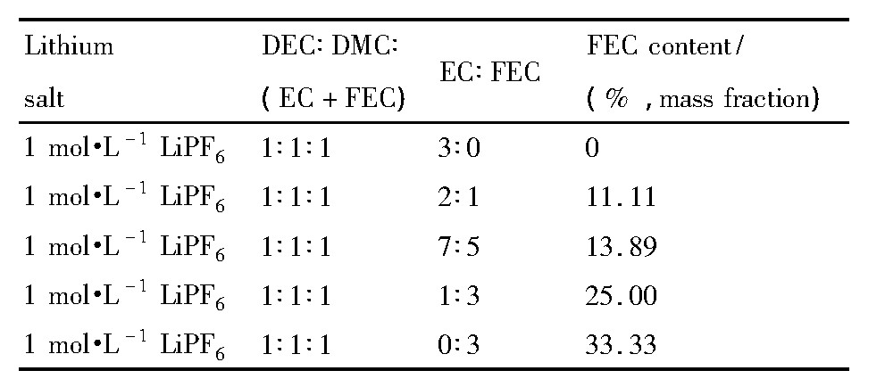
表1 FEC取代不同比例的EC电解液列表Table 1List of electrolyte with different proportions of EC replaced by FEC
组装的半电池在蓝电测试系统上进行充放电测试。循环性能测试:前两周为0.1C, 电压范围为2.5~4.7 V;之后0.3C循环, 电压范围为2.5~4.6 V (1C=200 m A・g-1) 。半电池循环40周后, 在手套箱中拆电池, 极片用DMC清洗掉表面的电解质后, 置于真空烘箱中烘干。利用X射线衍射 (XRD, PANalytical B.V.) 分析循环前后活性材料结构的变化, 扫描步长为0.02°, 扫描范围2θ为10°~90°。
2 结果与讨论
2.1 电化学性能分析
为考察FEC对电解液在高电压下氧化稳定性的影响, 比较了FEC不同取代量电解液的LSV曲线, 如图1所示。从图1中看出, FEC为0%时, 电解液在约4.3 V处开始发生氧化分解;FEC为11.11%及13.89%时, 电解液约在4.5 V处开始氧化分解;FEC为25%及33.33%时, 电解液约在4.6 V处开始有很小氧化电流。随着电压的升高, FEC为0%的电解液氧化分解反应剧烈增加, 在4.7 V时具有较高的氧化电流;而含有FEC的电解液随电压的升高氧化分解反应加剧相对较缓慢, 其中FEC为33.33%时在4.7 V仍具有很低的氧化电流。表明FEC可提高电解液的耐氧化稳定性, 且随着FEC取代量的增加, 电解液的耐氧化稳定性增强。从实验结果看到, FEC为33.33% (即EC被全部取代) 时, 电解液的电化学稳定窗口上限可达到4.7 V。
图2为不同电解液中GRT电极的首次充放电曲线, 电压范围为2.5~4.7 V, 电流密度为0.1C。从图2中看出, 首次充电曲线均有两个平台, <4.5 V的平台对应着Li+的脱出, 并伴随着Ni2+被氧化成Ni4+及Co3+被氧化成Co4+的过程[13,14];4.5~4.6 V的平台对应着Li2MnO3中的Li脱出, 形成Li2O和MnO2, 并伴随氧空位的产生[15,16,17]。另外, 可以发现FEC取代与否, 对GRT电极材料的脱嵌锂机制无明显影响。表2为各电解液中GRT电极的首次充放电比容量及首次库伦效率。从表2中看到, FEC为0%时, GRT电极的首次放电比容量为271.9 m Ah・g-1, 首次库伦效率为75.96%;而FEC为11.11%, 13.89%, 25.00%, 33.33%时, GRT的首次放电比容量分别提升了3.4, 7.6, 3.0, 5.6 m Ah・g-1及首次库伦效率分别提升了0.67%, 1.20%, 1.12%, 1.15%。表明FEC取代EC可提高GRT电极的首次放电比容量及首次库伦效率, 由于FEC的加入电解液中在4.7V电压下电解液溶剂分解减少, 电化学阻抗减小, 锂离子的传输效率提高, 从而GRT电极首次库伦效率提高, 首次放电比容量也相应提高[18,19]。
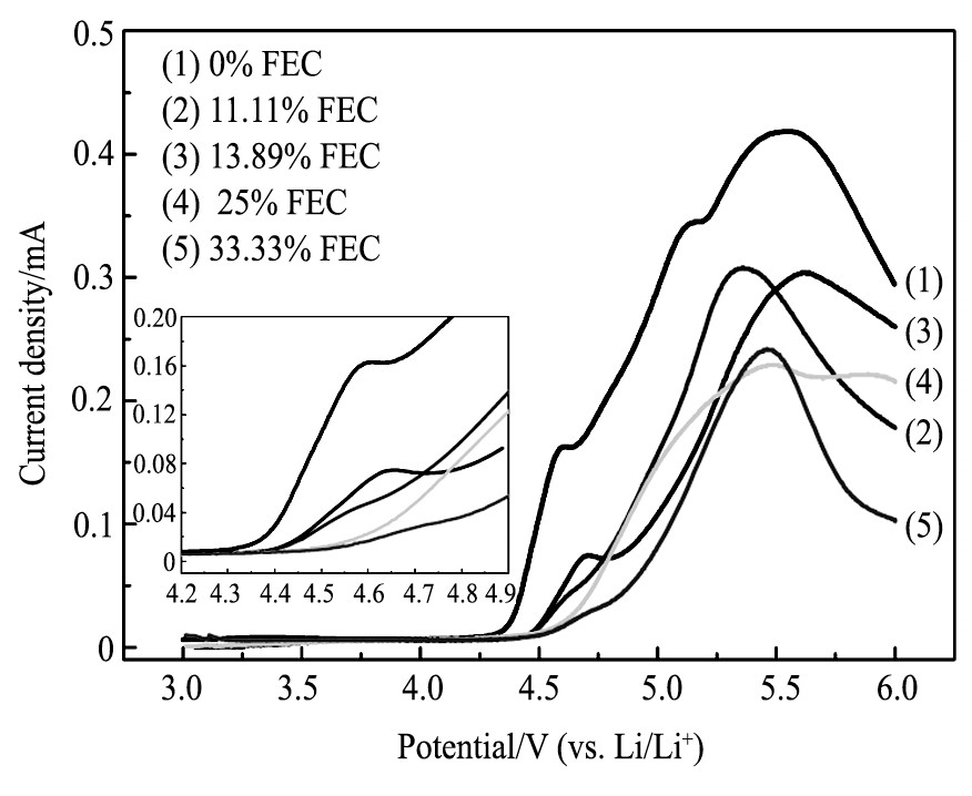
图1 不同电解液在室温下线性扫描伏安曲线Fig.1 LSVs of different electrolytes at room temperature
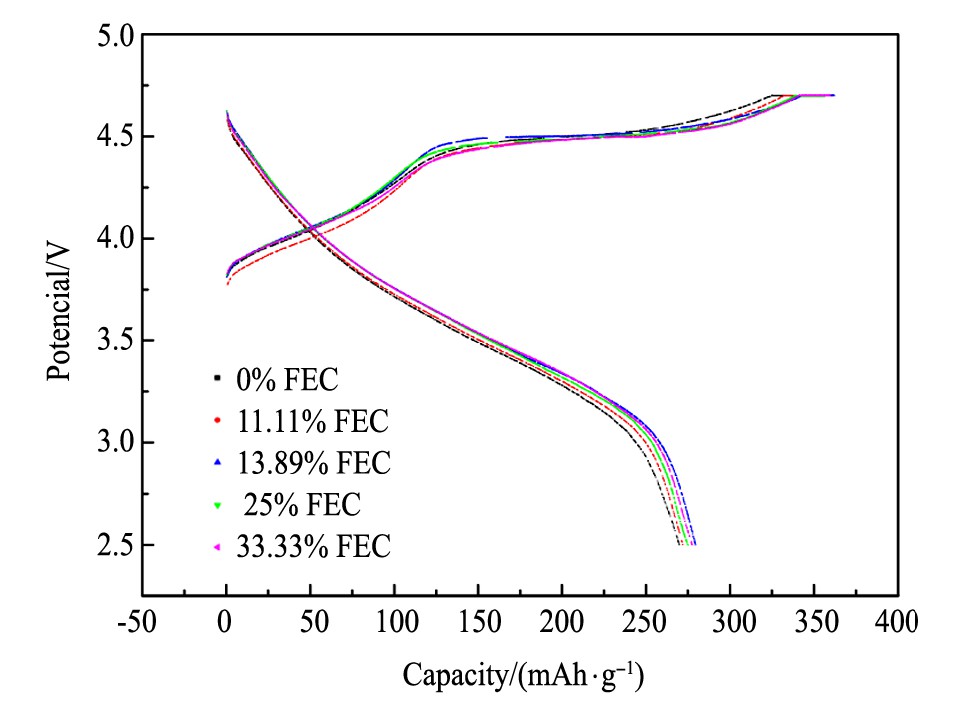
图2 不同电解液中GRT电极的首次充放电曲线Fig.2 First charge-discharge profiles of GRT electrode in dif-ferent electrolytes
图3为GRT电极在不同电解液中前100周的循环曲线 (a) 及放电中压的变化规律 (b) , 表3为GRT电极在0.3C电流密度下不同周次放电比容量及容量保持率。从图3 (a) 及表3可看出, FEC为0%时, GRT电极的放电比容量在前20周衰减相对较缓慢, 而在之后的循环衰减严重, 在60周的容量仅为115.0 m Ah・g-1, 容量保持率为49.89%;用FEC取代EC后, GRT电极的循环稳定性明显提高, 整个循环过程中衰减较缓慢, 且随着FEC比例的增大GRT电极的循环稳定性越高, 即FEC为33.33%时GRT的循环性能最佳, 在100周时容量为200.5 m Ah・g-1, 容量保持率为85.72%。由于FEC为0%时, EC等碳酸酯溶剂在4.7 V高电压下发生剧烈的氧化分解, 使得电解液组分和电极/电解液界面遭到破坏, 从而导致GRT电极容量急剧下降;而FEC部分或全部取代EC时, 电解液的氧化分解电位提高, 在循环过程中可一定程度抑制溶剂的分解, 从而提高了GRT电极的循环稳定性。从图3 (b) 可看出, 各电解液中GRT电极的放电中压均随循环逐渐下降, 而随着FEC取代量的增加, 基本呈现放电中压更高且衰减也越缓慢的趋势。因此, FEC的加入在一定程度上能缓减GRT材料中值电压的衰减。富锂锰基固溶体材料在循环过程中产生尖晶石结构, 会导致电极的放电中压下降[20,21]。这表明用FEC取代EC后的电解液在一定程度上能够提高GRT电极材料的结构稳定性。
表2 不同电解液中GRT的首次充放电比容量及库伦效率Table 2 First charge-discharge capacities and coulomb ef-ficiency of GRT electrode in different electrolytes 下载原图
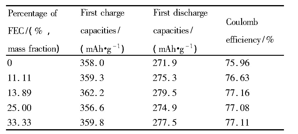
表2 不同电解液中GRT的首次充放电比容量及库伦效率Table 2 First charge-discharge capacities and coulomb ef-ficiency of GRT electrode in different electrolytes
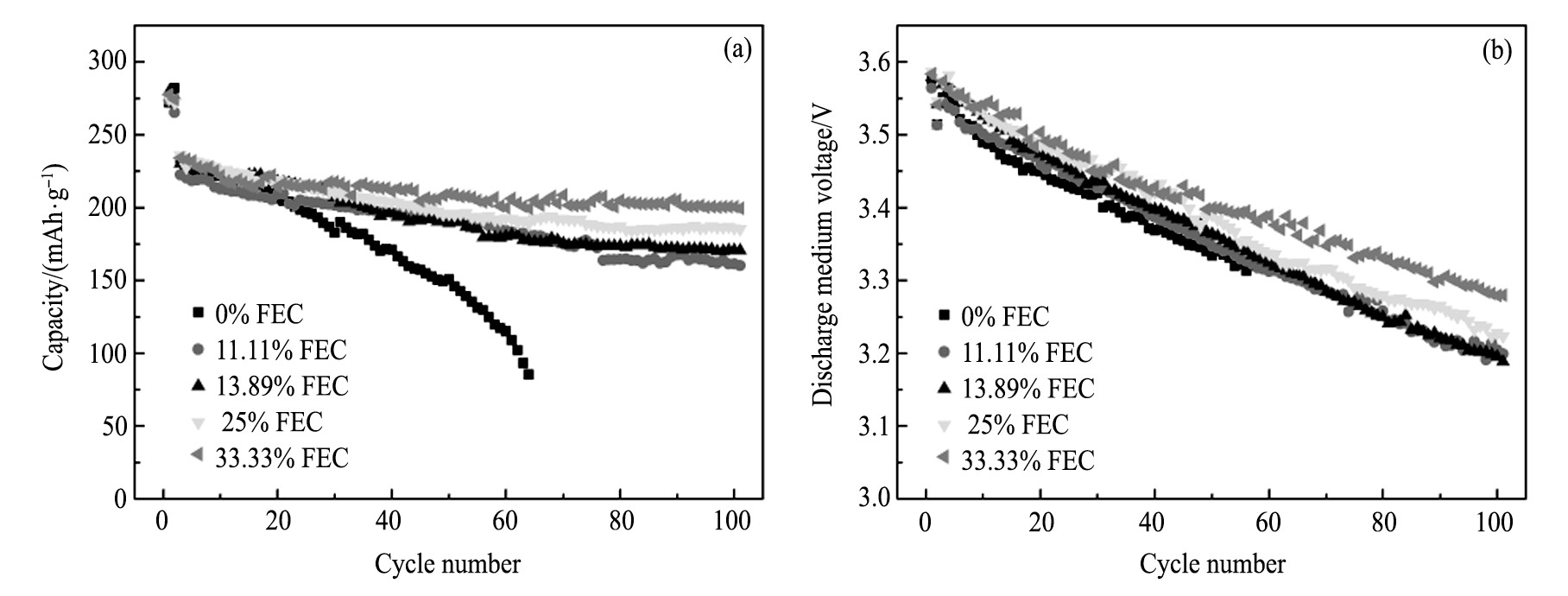
图3 不同电解液中GRT电极前100周的循环曲线及放电中压的变化规律Fig.3 Cycling performance (a) and charge of discharge medium voltage (b) of GRT electrode in different electrolytes
表3 不同电解液中GRT电极的循环性能Table 3 Cycling performance of GRT in different electro-lytes 下载原图
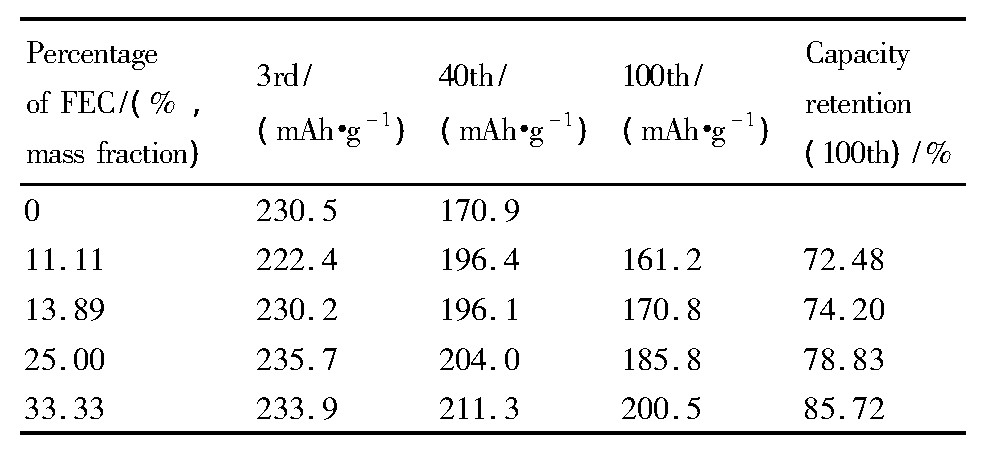
表3 不同电解液中GRT电极的循环性能Table 3 Cycling performance of GRT in different electro-lytes
为了进一步分析在循环过程中FEC对GRT电极极化的影响, 选择其中FEC为0%, 13.89%及33.33%3个比例的电解液, GRT电极在3 (0.3C循环的第1周) 、40, 100周的容量-电压微分曲线, 如图4 (a~c) 所示。从图4中看出, 随着循环周次的增加, 不同电解液中GRT电极的充电电压平台逐渐上升, 放电电压平台逐渐下降, 表明充放电过程中GRT电极的电化学极化不断增加;峰强度均随循环逐渐减小, 表明GRT电极的容量逐渐降低。从图4 (a) 看到, FEC为0%时, GRT电极在~3.6V处的还原峰逐渐减弱, 循环至40周时, ~3.0 V附近出现较强的还原峰, 表明GRT电极放电过程中出现新的还原反应, 电极结构发生了变化[22];循环至100周时, 无明显的还原峰, 近乎为一条直线, 表明GRT电极的放电比容量衰减严重。从图4 (b) 和 (c) 看到, FEC部分或全部取代EC时, GRT电极在~3.6 V处的还原峰衰减缓慢, 在40~100周的循环过程中还原峰位置移动很小, 峰强衰减同样很小, 表明FEC的添加大大降低了GRT电极在循环过程中的极化, 表现出较好的循环稳定性, 与图3 (a) 相对应。
2.2 电极结构XRD分析
当充电截止电压较高时 (>4.5 V) , 由于材料中O的脱出, 导致GRT电极结构不稳定, 循环性能随之变差, 为了了解在循环过程中FEC对GRT电极材料结构的影响, 对各电极的XRD图谱进行对比, 如图5所示。图5 (a) 为未循环GRT电极材料的XRD图谱, 2θ为20°~25°处微弱的衍射峰对应着Li2Mn O3组分, 其余衍射峰对应着层状结构的Li MO2, 而循环后的各电极中, Li2MnO3对应的峰消失, 这归因于Li2MnO3层活化, 表明过渡金属 (TM) 层中的Li-Mn有序排列被破坏[23]。图5 (b~d) 分别为电流密度为0.3C, 2.5~4.7 V电压范围内, 不同FEC比例的电解液中GRT电极材料循环40周后的XRD图谱。GRT材料中I[003]/I[104]表示层状结构的混排度, 原始材料的I[003]/I[104]>1.2, 层状结构良好[24], 而循环40周后各GRT电极材料的I[003]/I[104]<1.2, 表明层状结构遭到破坏, 尖晶石结构增加。从 (101) , (018) 及 (110) 衍射峰的局部放大图看到, 循环后, 衍射峰均向低角度移动, 由于材料的晶胞膨胀所致;峰均变宽、峰强变弱, 表明形成了纳米级别类尖晶石相, 材料结构的长程有序性变差[25,26]。循环后的GRT电极材料中, 在2θ约为38°处, 峰 (006) 与 (012) 合并形成了新峰;在2θ约为64°处, 同样出现了新峰, 且随FEC取代量的增加峰越不明显, 这些位置衍射峰均对应于立方相尖晶石结构[27]。此外, 循环后, (018) / (110) 两衍射峰间距均增大 (如表4所示) , 随FEC取代量的增加间距增加量越小。图5及表4表明, 循环40周后GRT电极材料结构发生了变化, 出现了尖晶石相, 随着FEC取代量的增加这种变化越小, 即FEC为33.33%时GRT电极材料与未循环GRT材料的结构最接近, 与其好的循环稳定性相对应。
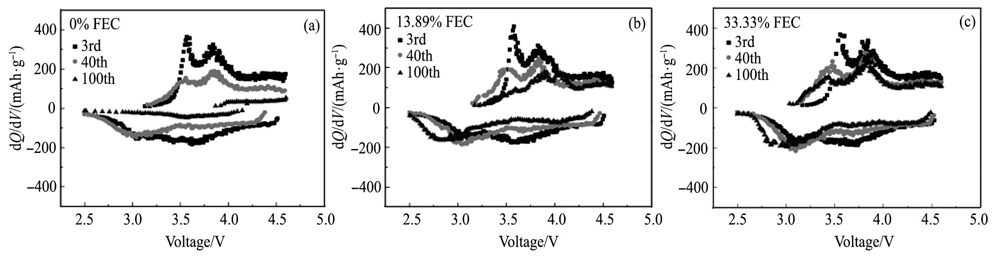
图4 FEC为0%, 13.89%, 33.33%时GRT电极在3, 40, 100周的容量微分曲线Fig.4 d Q/d V curves of GRT electrode in electrolyte with FEC of 0% (a) , 13.89% (b) and 33.33% (c) after 3, 40 and 100 cycles
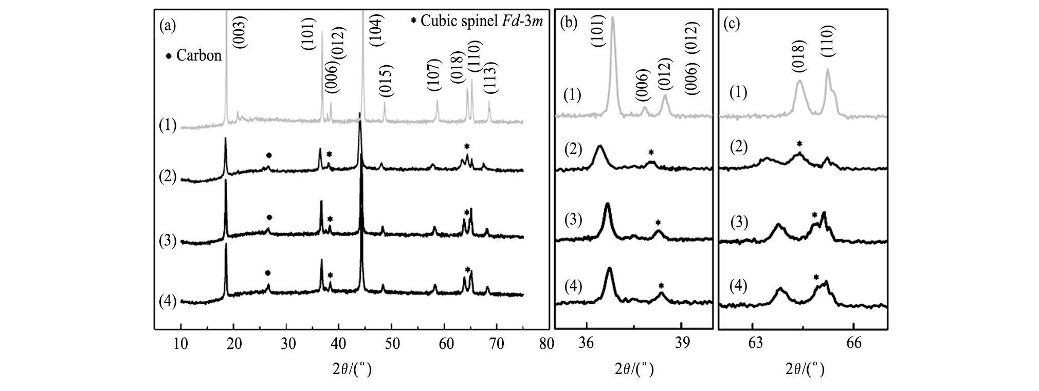
图5 不同的GRT电极的XRD图谱Fig.5 X-ray diffraction patterns of different GRT electrodes (a) and partial enlarged details of (006) / (012) (b) and (018) / (110) (c) diffraction peaks
(1) Fresh GRT electrode; (2) GRT electrode after cycled in 0%FEC electrolyte; (3) GRT electrode after cycled in 13.89%FECelectrolyte; (4) GRT electrode after cycled in 33.33%FEC electrolyte
表4 未循环GRT电极及不同电解液中循环后 (018) 与 (110) 的峰位差Table 4 Peak spacing between peaks (018) and (110) of fresh GRT and GRT after cycling in different e-lectrolyte 下载原图
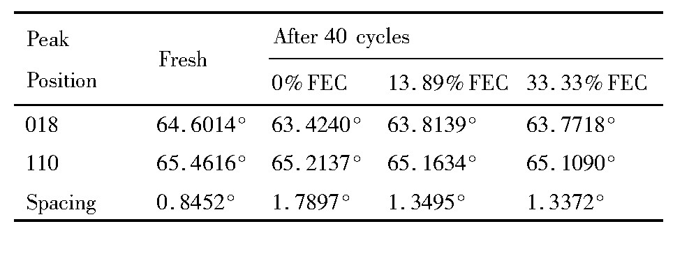
表4 未循环GRT电极及不同电解液中循环后 (018) 与 (110) 的峰位差Table 4 Peak spacing between peaks (018) and (110) of fresh GRT and GRT after cycling in different e-lectrolyte
3 结论
FEC作为溶剂部分或全部取代碳酸酯电解液中的EC, 提高了电解液的氧化分解电压, 且随着FEC取代量的增加, 电解液的抗氧化稳定性越好。FEC全部取代EC (33.33%FEC) 时, 电解液的电化学稳定窗口上限可达到4.7 V。在充电截止电压为4.7 V时, 电解液中FEC的取代量对GRT电极的电化学性能影响是线性相关的, 即随着FEC的取代量增加, GRT电极的循环稳定性增大, 放电中压衰减变缓;电解液中FEC的加入也在一定程度上缓减了GRT材料结构的变化, 且FEC的取代量越大, 循环后GRT结构变化越少, 越接近原始结构。因此, FEC为33.33% (即EC被FEC全部取代) 时, GRT电极的综合电化学性能最佳。
参考文献
[1] Mao G L. Development status and application prospect of lithium ion battery[J]. CEM:Industry Watch, 2009, 8:14. (毛国龙.锂离子动力电池发展现状及应用前景[J].中国电子商情:基础电子, 2009, 8:14.)
[2] Scrosati B, Hassoun J, Sun Y K. Lithium-ion batteries. A look into the future[J]. Energy&Environmental Science, 2011, 4 (9) :3287.
[3] Zhang Z C, Hu L B, Wu H M, Weng W, Koh M, Redfern P C, Curtiss L A, Amine K. Fluorinated electrolytes for 5 V lithium-ion battery chemistry[J]. Energy&Environmental Science, 2013, 6 (6) :1806.
[4] Liu X H, Zhuang W D, Peng M, Wang Z Y, Lu S G.Research progress in Li-rich manganese-based cathode material for Li-ion battery[J]. Chinese Journal of Rare Metals, 2017, 41 (5) :534. (刘祥欢, 庄卫东, 彭敏, 王振尧, 卢世刚.锂离子电池富锂锰基正极材料的研究进展[J].稀有金属, 2017, 41 (5) :534.)
[5] Wang Q Y, Liu J, Murugan A V, Manthiram A. High capacity double-layer surface modified Li[Li0. 2Mn0. 54Ni0. 13Co0. 13]O2cathode with improved rate capability[J]. Journal of Materials Chemistry, 2009, 19 (28) :4965.
[6] Wang L, Ma Y, Qu Y T, Cheng X Q, Zuo P J, Du C Y, Gao Y Z, Yin G P. Influence of fluoroethylene carbonate as co-solvent on the high-voltage performance of Li Ni1/3Co1/3Mn1/3O2, cathode for lithium-ion batteries[J]. Electrochimica Acta, 2016, 191:8.
[7] Hu L, Zhang Z, Amine K. Fluorinated electrolytes for Li-ion battery:an FEC-based electrolyte for high voltage Li Ni0. 5Mn1. 5O4/graphite couple[J]. Electrochemistry Communications, 2013, 35 (10) :76.
[8] Chen J, Zhang H, Li C. Enhanced electrochemical performance of high voltage spinel cathode by using fluoroethylene carbonate as an electrolyte ad-ditive[J]. International Conference on Advances in Energy and Environmental Science, 2015. 429.
[9] Markevich E, Salitra G, Fridman K, Sharabi R, Gershinsky G, Garsuch A, Semrau G, Schmidt M A, Aurbach D. Fluoroethylene carbonate as an important component in electrolyte solutions for high-voltage lithium batteries:role of surface chemistry on the cathode[J].Langmuir, 2014, 30 (25) :7414.
[10] Li Y, Lian F, Ma L L, Liu C L, Yang L, Sun X M, Chou K C. Fluoroethylene carbonate as electrolyte additive for improving the electrochemical performances of high-capacity Li1. 16[Mn0. 75Ni0. 25]0. 84O2material[J].Electrochimica Acta, 2015, 168:261.
[11] Hu M, Pang X, Zhou Z. Recent progress in high-voltage lithium ion batteries[J]. Journal of Power Sources, 2013, 237 (3) :229.
[12] Delp S A, Borodin O, Olguin M, Eisnerb C G, Allena J L, Jowa T R. Importance of reduction and oxidation stability of high voltage electrolytes and additives[J].Electrochimica Acta, 2016, 209:498.
[13] Chen C, Chen S, Shui M, Xu X, Zheng W, Feng L, Shu J, Ren Y L. Comparative studies on potential dependent electrochemical impedance spectroscopy of cathode material 0. 5Li2MnO3-0. 5LiNi0. 5Mn0. 5O2for the initial two charging cycles[J]. Current Applied Physics, 2015, 15 (2) :149.
[14] Buchholz D, Li J, Passerini S, Aquilanti G, Wang D, Giorgetti M. X-ray absorption spectroscopy investigation of lithium-rich, cobalt-poor layered-oxide cathode material with high capacity[J]. Chem. Electro. Chem., 2015, 2 (1) :85.
[15] Jarvis K A, Wang C C, Manthiram A, Ferreira P J.The role of composition in the atomic structure, oxygen loss, and capacity of layered Li-Mn-Ni oxide cathodes[J]. J. Mater. Chem. A, 2014, 2 (5) :1353.
[16] DupréN, Cuisinier M, Legall E, War D, Guyomard D.Contribution of the oxygen extracted from overlithiated layered oxides at high potential to the formation of the interphase[J]. Journal of Power Sources, 2015, 299:231.
[17] Mohanty D, Sefat A S, Payzant E A, Li J, Wood D L, Daniel C. Unconventional irreversible structural changes in a high-voltage Li-Mn-rich oxide for lithium-ion battery cathodes[J]. Journal of Power Sources, 2015, 283:423.
[18] Kasnatscheew J, Evertz M, Streipert B, Wagner R, Nowak S, Laskovic I C, Winter M. Changing established belief on capacity fade mechanisms:thorough investigation of Li Ni1/3Co1/3Mn1/3O2 (NCM111) under high voltage conditions[J]. Journal of Physical Chemistry C, 2017, 121:1521.
[19] Jorn R, Kumar R, Abraham D P, Voth G A. Atomistic modeling of the electrode-electrolyte interface in Liion energy storage systems:electrolyte structuring[J].Journal of Physical Chemistry C, 2016, 117 (8) :3747.
[20] Gu M, Belharouak I, Zheng J M, Wu H M, Xiao J, Genc A, Amine K, Thevuthasan S, Baer D R, Zhang JG, Browning N D, Liu J, Wang C M. Formation of the spinel phase in the layered composite cathode used in Liion batteries[J]. Acs Nano, 2013, 7 (1) :760.
[21] Nayak P K, Grinblat J G, Levi M, Markovsky B, Aurbach D. Structural and electrochemical evidence of layered to spinel phase transformation of Li and Mn rich layered cathode materials of the formulae x Li[Li1/3Mn2/3]O2 (1-x) Li Mn1/3Ni1/3Co1/3O2 (x=0. 2, 0. 4, 0. 6) upon cycling[J]. Journal of the Electrochemical Society, 2014, 161 (10) :A1534.
[22] Zhang H Y. Temperature-Sensitive Electrodes with Thermal Protection Mechanism for Lithium-Ion Batteries[D]. Beijing:General Research Institute for Nonferrous Metals, 2016. 124. (张海燕.温度敏感电极在锂离子电池中的应用研究[D].北京:北京有色金属研究总院, 2016. 124.)
[23] Ito A, Li D, Sato Y. Cyclic deterioration and its improvement for Li-rich layered cathode material Li[Ni0. 17Li0. 2Co0. 07Mn0. 56]O2[J]. Journal of Power Sources, 2010, 195:567.
[24] Ohzuku T, Ueda A, Nagayama M, Iwakoshi Y, Komori H. Comparative study of Li Co O2, Li Ni Co O2and Li Ni O2for 4 volt secondary lithium cells[J]. Electrochimica Acta, 1993, 38 (9) :1159.
[25] Mohanty D, Sefat A S, Li J L, Meisner R A, Rondinone A J, Payzant E A, Abraham D P, Wood D L, Daniel C.Correlating cation ordering and voltage fade in a lithiummanganese-rich lithium-ion battery cathode oxide:a joint magnetic susceptibility and TEM study.[J]. Physical Chemistry Chemical Physics, 2013, 15 (44) :19496.
[26] Riekehr L, Liu J L, Schwarz B, Sigel F, Kerkamm I, Xia Y Y, Ehrenberg H. Fatigue in 0. 5Li2MnO3:0. 5Li (Ni1/3Co1/3Mn1/3) O2positive electrodes for lithium ion batteries[J]. Journal of Power Sources, 2016, 325:391.
[27] Wu F, Li N, Su Y F, Shou H F, Bao L Y, Yang W, Zhang L J, An R, Chen S. Spinel/layered heterostructured cathode material for high-capacity and high-rate Liion batteries[J]. Advanced Materials, 2013, 25 (27) :3722.

