文章编号:1004-0609(2015)02-0523-11
铜钢复合冷却壁传热及热应力分析
刘 奇1,程树森1,牛建平2,刘东东2
(1. 北京科技大学 冶金与生态工程学院,北京 100083;
2. 河北省万全县丰华有色金属加工厂,张家口076250)
摘 要:通过建立铜钢复合冷却壁传热及热应力分布数学模型,研究了铜钢复合冷却壁与铜冷却壁、铸钢冷却壁的传热性能差异及其铜钢界面热应力分布。结果表明:煤气温度为1200 ℃时,高炉内无渣皮覆盖铜钢复合冷却壁肋热面最高温度为180 ℃,较相同煤气温度下铜冷却壁的最高温度高约30 ℃,较铸钢冷却壁的最高温度低约520 ℃。铜钢复合冷却壁具备铜冷却壁的传热性能。铜钢界面边缘正应力σz大于0,表现为受拉状态;冷面增加加强筋后,铜钢界面边缘正应力σz小于0,表现为受压状态,且最大等效应力降低至114.45 MPa,低于铜钢复合板的高温强度。高炉内铜钢复合冷却壁不会发生铜钢界面分离破损。热态试验中铜钢复合冷却壁温度计算值与测量值吻合较好,验证了数学模型的准确性。
关键词:高炉;铜钢复合冷却壁;传热;热态试验;热应力
中图分类号:TF573.1 文献标志码:A
Heat transfer and thermal stress analysis of copper steel composite stave
LIU Qi1, CHENG Shu-sen1, NIU Jian-ping2, LIU Dong-dong2
(1. School of Metallurgy and Ecology Engineering, University of Science and Technology Beijing,
Beijing 100083, China;
2. Hebei Wanquan Fenghua Nonferrous Manufactory, Zhangjiakou 076250, China)
Abstract: The heat transfer difference of copper steel composite stave with copper stave and cast steel stave and thermal stress distribution of copper steel interface were investigated through establishing a mathematical model of heat transfer and thermal stress distribution of copper steel composite stave. The results show that the maximum temperature at the rib of copper steel composite stave without the accretion is 180 ℃ when the furnace temperature is 1200 ℃, which is about 30 ℃ higher than that of copper stave and 520 ℃ lower than that of cast steel stave. Copper steel composite stave has the same heat transfer performance as copper stave. The normal stress σz at the free edge of copper steel interface is larger than 0 and it is submitted to tension. When welding the copper steel composite stave onto the reinforced rib, the normal stress σz at the free edge of copper steel interface is lower than 0 and it is submitted to compression, and the maximum equivalent stress of copper steel interface decreases to 114.45 MPa and it is less than the elevated temperature strength of copper steel composite plate. Copper steel composite stave will not be damaged by separation of copper and steel layer in blast furnace. The calculated and measured temperature of copper steel composite stave in the thermal test agree well, which verifies the validity of the mathematical model.
Key words: blast furnace; copper steel composite stave; heat transfer; thermal test; thermal stress
高炉长寿技术对高炉大型化发展和提高企业经济效益意义重大,而高炉寿命取决于炉体冷却设备的寿命,提高炉体冷却设备的寿命成为高炉长寿技术发展的主要问题。随着高炉高煤比和高风温等操作技术的发展,高炉炉腹、炉腰和炉身下部等热负荷较高区域工作环境恶化,炉体冷却设备受热流冲击严重,冷却设备容易发生损坏。提高热负荷较高区域冷却设备的寿命成为高炉长寿的研究重点[1-6]。
国内外高炉热负荷较高区域普遍采用铜冷却壁提高高炉寿命[7-8]。铜冷却壁具有导热系数高(约为铸钢的8倍)、抗热流冲击和抗热震性能优良等特点,满足高炉热负荷较高区域冷却设备的传热性能要求。但铜冷却壁导热系数大也增加了其进出水管根部的焊接加工难度。在进出水管与壁体焊接过程中,需将其预热至500 ℃左右,而纯铜导热性好,热量迅速从加热区传导出去,体积(2500 mm×788 mm×120 mm)大,对局部区域预热至500 ℃难度高,若对铜冷却壁整体预热,容易导致晶粒粗大,相互之间结合能力降低。另一方面,铜在500~600 ℃呈现“中温脆性”,焊缝熔池内的铜液在凝固过程中,铋、铅和硫等杂质与铜形成低熔点共晶体分布在晶界上,焊接过程中容易产生热裂纹。在高炉热负荷较高区域,铜冷却壁经受高热流冲击作用,在渣皮脱落条件下,工作温度迅速升高,基体纯铜材料强度随温度升高明显降低,壁体分布的热应力容易超过其屈服强度而发生塑性变形。国内部分高炉使用的铜冷却壁已出现塑性变形及进出水管沿根部断裂问题[9-10]。铜冷却壁塑性变形和进出水管断裂照片如图1所示。
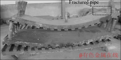
图1 铜冷却壁塑性变形和进出水管断裂照片
Fig. 1 Photo of plastic deformation and water pipes fracture of copper stave
针对高炉热负荷较高区域铜冷却壁因强度不足引起的屈服失效及进出水管沿焊接位置断裂问题,在保证良好传热性能的基础上,开发了铜钢复合冷却壁。铜钢复合冷却壁以纯铜板为热面传热层,保留铜冷却壁良好的传热性能,以20 g钢板作为冷面被覆层,提高了壁体的强度,避免铜冷却壁发生屈服失效问题,以Q235无缝钢管为进出水管,进出水管与壁体为低碳钢焊接结合,克服铜冷却壁进出水管断裂问题。
QIAN等[11]通过建立高炉铜冷却壁炉墙传热数学模型,研究了铜冷却壁设计参数对其传热性能的影响;YEH等[12]采用共轭传热分析法研究了高炉铜冷却壁热面挂渣厚度及燕尾槽内耐火砖厚度对其传热性能的影响;吴桐等[13]应用铜冷却壁一维传热数学模型研究了炉内边缘煤气温度、冷却水速及水温对其挂渣厚度的影响。由于以上数学模型仅限于铜冷却壁,不能应用于铜钢复合冷却壁的传热分析。刘增勋等[14]建立了铜钢复合冷却壁稳态传热数学模型,研究了炉内边缘煤气温度及冷却水速对其温度分布的影响;邢书明等[15]模拟了高炉内铜钢复合冷却壁的温度分布;竺超今等[16]建立高炉内铜钢复合冷却壁的传热及热应力分布数学模型,研究了炉内操作参数对其温度及热应力分布的影响。然而,以上这些有关铜钢复合冷却壁的研究主要集中于传热分析,而热应力分析涉及较少,且仅采用数值模拟方法,计算结果缺乏试验验证。另一方面,以上研究中仅以等效应力表征铜钢复合冷却壁的热应力分布,但铜钢复合冷却壁铜钢界面的受力状态,即受拉或受压,对分析其在高炉内的安全性具有重要意义。本文作者建立铜钢复合冷却壁温度及热应力分布数学模型,并以热态试验工况下铜钢复合冷却壁温度分布计算值和测量值对比分析验证了数学模型的准确性,并应用数学模型计算了高炉内铜钢复合冷却壁热面无渣皮覆盖条件下的温度及热应力分布,分析了铜钢复合冷却壁的传热性能,并对铜钢界面进行热应力分析。
1 铜钢复合冷却壁几何模型的建立
图2所示为铜钢复合冷却壁几何模型。铜钢复合冷却壁几何模型主要包括铜钢复合冷却壁、填料层和炉壳等。铜钢复合冷却壁(见图2(a)),以T2纯铜板为热面传热层(也称铜层),20 g钢板为冷面被覆层(也称钢层),铜板与钢板以爆炸焊接方式结合,确保铜板与钢板界面具有较高的结合强度,其高温拉伸力学性能实验结果如表1所列,超过相同温度下T2纯铜的高温抗拉强度[17];铜钢复合冷却壁铜层厚度为60 mm,钢层厚度为20 mm,热面铜层开设燕尾槽(见图2(b)),燕尾槽深度为30 mm,上宽为60 mm,下宽为66 mm。本体冷面加工4个冷却水道,冷却水道截面形状为半圆与矩形结合的复合型水道(见图2(c)),且其位于铜钢复合冷却壁铜钢界面附近(见图2(d)),其当量直径(4倍冷却水道截面面积与其周长的比值)为54 mm、填料层厚度为80 mm、炉壳厚度为30 mm。
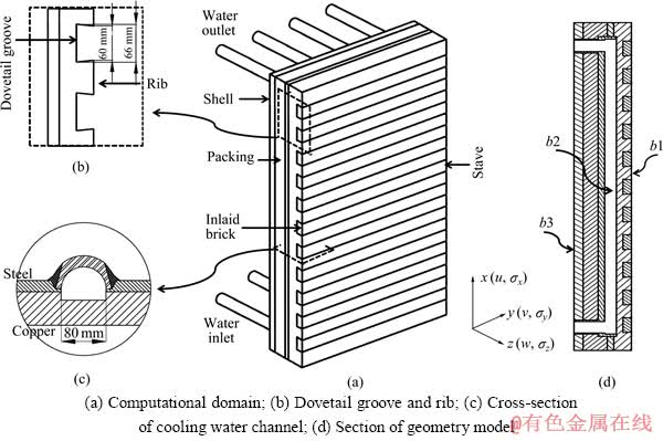
图2 铜钢复合冷却壁几何模型
Fig. 2 Geometry model of copper steel composite stave
表1 铜钢复合板的高温强度
Table 1 Elevated temperature strength of copper/steel composite plate

2 传热及热应力分布数学模型
2.1 控制微分方程
根据热弹性力学理论可知,铜钢复合冷却壁温度及热应力分布计算的控制方程如下。
1) 传热控制微分方程
铜钢复合冷却壁内部传热为无内热源的三维稳态导热,控制方程为
 (1)
(1)
2) 物理方程
 (2)
(2)
3) 平衡微分方程
 (3)
(3)
4) 几何方程
 (4)
(4)
式中:λ(t)为导热系数,W/(m・℃);t为壁体温度,℃;σi(i=x,y,z)为x、y、z方向上的热应力,MPa;εi(i=x,y,z)为x、y、z方向上的热应变;τxy、τyz、τzx为xy、yz、zx面的切应力,MPa;γxy、γyz、γzx为xy、yz、zx面的切应变;u、v、w分别为x、y、z向位移,m;G为剪切模量,MPa;E为材料的弹性模量,MPa;μ为泊松比; 为材料的热膨胀系数,℃-1。
2.2 边界条件
1) 高温煤气与铜钢复合冷却壁热面边界b1(见图2(d))为对流和辐射的综合换热过程[18],即
 (5)
(5)
 (6)
(6)
式中:tf为热面煤气温度,℃; 为边界面法向温度梯度,℃/m;thot-face为铜钢复合冷却壁热面温度,℃;αtotal为高温煤气与铜钢复合冷却壁热面的综合换热系数,W/(m2・℃);
 为对流换热系数,W/(m2・℃);
 为辐射换热系数,W/(m2・℃)。
2) 冷却水与管内壁边界b2为对流换热,即
 (7)
(7)
式中: 为冷却水平均温度,℃;
 为冷却水与管内壁的对流换热系数,W/(m2・℃);对流换热系数与冷却水速v、冷却水热物性参数、管道截面形状等有关,由于管内温度分布不均匀,进水温度tin低于出水温度tout,取进出水温度的算术平均值作为定性温度,确定冷却水热物性参数;冷却水道截面为半圆与矩形组成的复合型水道,属于非圆形截面管道,取管道的当量直径de作为定型尺寸。由管内强制对流给热方程计算,即
 (8)
(8)
 (9)
(9)
 (10)
(10)
式中:Ref为冷却水强制对流时对应的雷诺数; 为冷却水的运动粘性系数,m2/s;Nuf为冷却水强制对流时对应的努塞尔特准数;Prf为冷却水平均温度下对应的普朗特数;λw为冷却水的导热系数,W/(m・℃)。
3) 周围环境与炉壳外表面边界b3为自然对流和辐射的综合换热过程,即
 (11)
(11)
 (12)
(12)
式中:ta为环境温度,℃;tshell为炉壳表面温度,℃; 为炉壳与周围环境之间的综合换热系数,W/(m2・℃);
 为炉壳与周围环境之间的自然对流换热系数,W/(m2・℃);
 为炉壳与周围环境之间的辐射换热系数,W/(m2・℃)。
自然对流换热系数由式(13)、(14)和(15)计算:
 (13)
(13)
 (14)
(14)
 (15)
(15)
式中:Gr、Pra、Nua分别为空气自然对流时对应的格拉晓夫准数、普朗特数和努塞尔特准数;β为空气的温度膨胀系数,℃-1; 为空气的运动粘性系数,m2/s;λa为空气的导热系数,W/(m・℃);g为重力加速度,m/s2;h为炉壳高度,m;△t为炉壳外表面温度与空气温度的差值,△t=tshell-ta,℃;Gr为格拉晓夫准数;C、n为常数。
辐射换热系数由式(16)计算
 (16)
(16)
式中:εshell为炉壳的黑度;C0为黑体的辐射系数,为5.67 W/(m2・℃4)。
4) 其他面b4为绝热边界,即
 (17)
(17)
5) 约束边界条件
根据高炉内冷却壁的安装方式,即以定位销及螺栓固定于高炉炉壳,设定铜钢复合冷却壁冷面定位销及固定螺栓与炉壳接触界面沿x、y向位移为0,z向位移与炉壳相同。由于铜钢复合冷却壁温度升高后,发生膨胀变形,相邻铜钢复合冷却壁之间相互挤压,因而,设定铜钢复合冷却壁侧面受到10 MPa的压力。其他面设定为自由边界。
2.3 物性参数
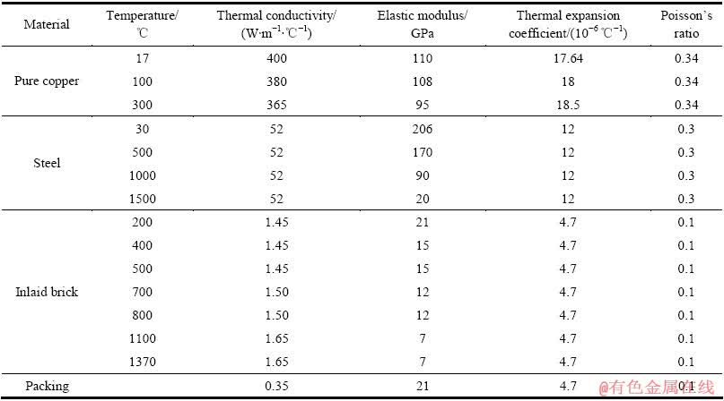
铜钢复合冷却壁热应力分布计算涉及到材料的导热系数、弹性模量、泊松比、热膨胀系数等物性参数。相应材料的物性参数[19-20]如表2所列。
表2 材料的导热系数及力学性能
Table 2 Thermal conductivity and mechanical properties of materials
3 热态试验与数学模型验证
为了验证本数学模型的准确性,对1:1比例铜钢复合冷却壁进行了热态试验,测试热态试验条件下铜钢复合冷却壁的温度分布,并根据热态试验检测数据获得铜钢复合冷却壁传热的边界条件,应用数学模型计算热态试验工况下铜钢复合冷却壁的温度分布,将计算结果与测量结果进行对比分析。图3所示为铜钢复合冷却壁热态试验系统。热态试验系统由热态试验炉、铜钢复合冷却壁、温度检测系统、冷却水循环系统和数据采集系统等构成。热态试验炉内装入焦炭燃料至烟道下沿,以铜钢复合冷却壁热面作为热态试验炉内表面,将其吊装于热态试验炉炉顶,以热态试验炉两侧风机向炉内鼓入焦炭燃烧所需助燃空气,焦炭未完全燃烧产生的高温煤气与铜钢复合冷却壁热面发生强制对流换热和辐射换热后由两侧烟道排出炉外。水箱内冷却水由水泵送入冷却水道,与管壁发生对流换热后排回冷却水箱,构成冷却水循环系统。
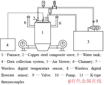
图3 铜钢复合冷却壁热态试验系统
Fig. 3 Thermal test stand of copper steel composite stave
热态试验过程中,铜钢复合冷却壁肋及镶砖内部不同深度位置埋设K型热电偶(即镍铬镍硅热电偶),测量精度为±2.5 ℃,热电偶分布位置如图4所示,其中12~15距肋热面10 mm,21~25距肋热面15 mm,47、49、51距镶砖热面10 mm,48、50、52距镶砖热面15 mm,以相同位置或对称位置上不同深度热电偶测量值计算此位置对应热面温度。热态试验炉内部插入铂铑铂热电偶,检测炉温。铜钢复合冷却壁进水管与出水管安装无线数字温度传感器(图3中数字7),型号为ADE-WT3,测量精度为±0.05 ℃,检测进水温度与出水温度。进水管上安装无线数字流量传感器(图3中数字8),型号为ADE-WF,测量精度为0.5%,测量冷却水流量。
根据热态试验中测试数据计算得到热态试验工况下铜钢复合冷却壁传热的边界条件:1) 铜钢复合冷却壁热面与高温煤气的综合换热系数39 W/(m2・℃),煤气温度为1100 ℃;2) 冷却水与管道内壁的对流换热系数为1659.4 W/(m2・℃);3) 铜钢复合冷却壁冷面及侧面与周围环境之间的综合换热系数为11.17 W/(m2・℃)。根据以上边界条件计算得到炉温为1100 ℃下铜钢复合冷却壁的温度分布,并与热电偶测量值进行对比,其结果如图5所示。由图5可知,计算值与测量值之间的差值约为0~6.6 ℃,相对误差约为0~9.09%。计算值与测量值基本吻合,可以应用此数学模型计算高炉工况下铜钢复合冷却壁的温度及热应力分布。

图4 铜钢复合冷却壁热电偶布置图
Fig. 4 Schematic diagram of thermocouples position of copper steel composite stave

图5 1100 ℃炉温下铜钢复合冷却壁温度测量值与计算值对比
Fig. 5 Comparison of measured and calculated temperature of copper steel composite stave at furnace temperature of 1100 ℃
4 结果与分析
4.1 铜钢复合冷却壁传热分析
高炉内铜钢复合冷却壁热面与高温煤气的综合换热系数为232 W/(m2・℃),煤气温度为1200 ℃[21];冷却水流速为2.0 m/s,冷却水平均温度约为40 ℃,根据式(8)~(10),计算得到冷却水与管内壁的对流换热系数为7418.32 W/(m2・℃);假设炉壳温度为70 ℃,周围空气温度为20℃,根据式(13)~(16),炉壳与周围环境之间的综合换热系数为11.17 W/(m2・℃)。根据以上边界条件,利用ANSYS有限元软件计算得到高炉工况下铜钢复合冷却壁温度分布,如图6所示。图中未显示填料层及炉壳的温度分布,为了便于分析,图6中给出铜钢复合冷却壁侧面底端局部放大图(见图6中左图)。从图6可知,当铜钢复合冷却壁热面无渣皮覆盖,煤气温度为1200 ℃,温度分布达到稳态时,顶底端肋热面最高温度约为180 ℃,中间肋热面最高温度约130 ℃,顶底端肋热面温度普遍高于中间肋。由于顶底端肋与冷却水道的距离较大,传热热阻大,导致其温度相对中间肋较高;镶砖热面最高温度达到967 ℃左右,通常情况下,高炉内耐火砖工作面温度高于850 ℃时,容易发生化学侵蚀破损[21]。这可能是燕尾槽内镶砖容易发生脱落的原因。由图6中y=0 mm截面局部温度分布放大图可知,镶砖及肋温度由热面至冷面逐渐降低,铜层和钢层内部温度普遍低于镶砖内部温度,主要由于镶砖传热热阻增大所致。铜钢复合冷却壁肋热面的最高温度低于铜的极限工作温度230 ℃[22],高炉内铜钢复合冷却壁处于安全工作温度范围之内。与相同条件下铜冷却壁[23]和铸钢冷却壁[24]温度分布相比,铜钢复合冷却壁肋热面最高温度较铜冷却壁高约30 ℃,较铸钢冷却壁肋热面最高温度低约520 ℃。可见,铜钢复合冷却壁继承了铜冷却壁良好的传热性能,并克服了铸钢冷却壁传热性能差的不足。

图6 铜钢复合冷却壁温度分布
Fig. 6 Temperature distribution of copper steel composite stave
图7所示为铜钢复合冷却壁厚度方向温度分布。图7中给出壁体中心对称线上温度分布,中心对称线位置如图7中右下角分图所示。从图7可以看出,铜钢复合冷却壁冷面温度约为99 ℃,铜钢界面温度约为104 ℃,热面温度约为133 ℃,厚度方向温度由冷面至热面逐渐增加,钢层温度普遍低于铜层温度,且温度梯度小于铜层内温度梯度。钢层位于冷面与冷却水道之间,铜层位于冷却水道与热面之间,如图2(c)所示,热面传入热量几乎全部由冷却水带走,由铜层传入钢层的热量少,导致冷面钢层处于较低的工作温度。冷却水道位于铜钢界面附近的设计,使得铜钢界面在冷却水道较强的冷却强度下,处于较低的工作温度,此种冷却水道布置有利于降低铜层与钢层之间因热膨胀量不同所致的热应力。
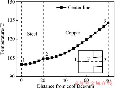
图7 铜钢复合冷却壁厚度方向温度分布
Fig. 7 Temperature distribution along copper steel composite stave thickness
4.2 铜钢复合冷却壁热应力分析
图8所示为铜钢复合冷却壁等效应力分布。由于铜钢复合冷却壁关于中心纵截面对称,图中仅给出对称部分的等效应力分布。图8中左图为铜钢复合冷却壁中心纵截面顶端局部放大图。由图8可知,铜钢复合冷却壁最大等效应力达到257.89 MPa,位于冷面钢层与螺栓接触面上。顶底端肋等效应力普遍高于中间肋,由于顶底端肋温度高所致。由图8中铜钢复合冷却壁截面上等效应力分布可知,铜层与钢层焊合面(即铜钢界面)上等效应力相对其他位置的更大,且铜钢界面上等效应力由自由边缘至中心逐渐减小,铜钢界面自由边缘位置达到最大等效应力142.91 MPa。从图6中铜钢复合冷却壁的温度分布可知,铜钢复合冷却壁顶底端温度相对其他位置的更高,传热性能更差,而在相同的约束条件下,温度越高位置处产生的热应力越大;另一方面,铜钢界面因铜层与钢层热膨胀系数不同所致的热应力相对其他位置的更大。因而,铜钢界面边缘位置达到最大等效应力。由以上分析可知,铜钢界面边缘位置相对其他位置存在较严重的应力集中问题。

图8 铜钢复合冷却壁等效应力分布
Fig. 8 Equivalent stress distribution of copper steel composite stave
4.3 铜钢界面热应力分析
图9所示为铜钢复合冷却壁厚度方向(ab线)上等效应力(Von Mises stress)和正应力(σx、σy、σz)分布。ab线位于铜钢复合冷却壁中心纵截面中部,如图9中右侧铜钢复合冷却壁纵向剖视图所示。从图9中可以看出,铜钢复合冷却壁厚度方向等效应力(Von Mises stress)最大值位于铜钢界面上(与冷面距离为20 mm),约为87.35 MPa,等效应力由铜钢界面至冷面逐渐降低,由铜钢界面至热面也逐渐降低,热面等效应力最小,约为23.72 MPa,铜钢界面等效应力大的主要原因是铜层与钢层之间温度不同,热膨胀系数不同,在界面位置存在因热膨胀量不同导致的热应力;从正应力σx分布可知,冷面至热面正应力σx小于0,说明铜层和钢层沿x向受压;从正应力σy分布可知,由冷面至铜钢界面的正应力σy大于0,说明钢层沿y向受拉,由铜钢界面至热面的正应力σy小于0,说明铜层沿y向受压。铜层沿x、y向表现为受压主要由于铜层与钢层的热膨胀量不同所致,铜层与钢层相比,温度高、热膨胀系数大,铜层沿x、y向伸长量大于钢层,铜层受到钢层的限制作用,表现为受压;而钢层沿x向受压,沿y向受拉主要是由于钢层温度低于铜层温度,热膨胀系数小,钢层沿x、y向伸长量小于铜层的,在不考虑铜钢复合冷却壁弯曲变形所致的压应力条件下,钢层沿x、y向应受到拉应力。但实际上铜钢复合冷却壁沿高度方向(x向)以弯曲变形为主,说明冷面钢层弯曲变形所致的压应力大于其他应力,而y向在定位销及固定螺栓的约束下几乎未发生弯曲变形,即冷面钢层沿y向弯曲变形所致的压应力几乎为0。因此,钢层沿x向受压,沿y向受拉。由正应力σz分布可知,由冷面至热面的正应力σz小于0,表现为受压状态。假设冷面中心无定位销,因热面温度高于冷面,壁体将发生弯曲变形,壁体中心向热面凸出,此时线ab上各点沿z向不受约束,近似为自由膨胀,沿z向正应力σz应等于0,而实际上,冷面中心有定位销,定位销在炉壳的固定约束作用下,限制壁体中心向热面凸出,相当于壁体中心被定位销拉向冷面,在此过程中,热面肋将受到两侧镶砖的挤压作用,导致线ab上各点沿z向正应力σz小于0。
图10所示为铜钢界面纵向线FO上的等效应力(Von Mises stress)及正应力(σx、σy、σz)分布。纵向线FO位置如图10中右侧铜钢复合冷却壁纵向剖视图所示。因铜钢复合冷却壁关于yz面对称,图中仅给出铜钢界面纵向线EF一半FO上的等效应力及正应力分布。铜钢界面等效应力分布显示,铜钢界面等效应力由边缘至中心逐渐降低,边缘位置达到最大等效应力,约为142.91 MPa,中心达到最小等效应力,约为63.27 MPa,根据铜钢复合板的高温拉伸试验结果可知,试验温度为175 ℃时,其抗拉强度为304 MPa,即铜钢界面的结合强度达到304 MPa,其上最大等效应力小于结合强度。从铜钢界面x、y向正应力分布可知,铜钢界面FO线上各点沿x、y向正应力小于0,表现为受压状态。铜钢复合冷却壁热面温度高于冷面温度,热面沿x、y向的伸长量高于冷面的,壁体发生弯曲变形,壁体中心向热面凸出,顶底面及侧面沿z负向产生位移,壁体内部将受到弯曲变形导致的热应力,根据弯曲变形的性质可知,二维平板发生弯曲变形时,其过形心的平面(与xy坐标面平行)两侧受力状态不同,贴近热面受拉应力,贴近冷面受压应力。由于铜钢界面远离热面,贴近冷面,即铜钢界面沿x、y向受压。因此,铜钢界面沿x、y向正应力小于0。从铜钢界面沿z向正应力分布可知,铜钢界面沿z向正应力在边缘位置达到最大z向正应力43.53 MPa,表现为受拉状态,远离边缘位置z向正应力小于0,表现为受压状态。

图9 铜钢复合冷却壁厚度方向(线ab)等效应力及正应力分布
Fig. 9 Equivalent stress and normal stress distribution through copper steel composite stave thickness

图10 铜钢界面纵向线FO上等效应力及正应力分布
Fig. 10 Equivalent stress and normal stress distribution at vertical line FO of copper steel interface
铜钢界面最大等效应力小于铜层与钢层的结合强度,从静态强度方面考虑,铜层与钢层之间不会发生界面分离问题。但铜钢界面边缘位置沿z向正应力大于0,表现为受拉状态,铜钢复合冷却壁工作过程中,铜钢界面长期受到z向拉伸作用,可能出现蠕变所致的界面分离问题。若将铜钢界面的受拉状态更改为受压状态,并减小铜钢界面边缘位置上的热应力,使得其上最大等效应力远小于铜钢界面的结合强度,铜层与钢层在相互挤压作用下,将不易发生界面分离问题。
4.4 结构优化后铜钢界面热应力分析
从远离边缘位置铜钢界面上z向正应力分布可知,其值小于0,表现为受压状态,主要由于远离边缘位置受到定位销及螺栓的约束作用大,弯曲变形小所致,可见,若将铜钢复合冷却壁边缘施加类似定位销及螺栓的约束作用,则铜钢界面边缘位置受拉状态可能更改为受压状态。根据铜钢复合冷却壁结构特点,在保证铜钢复合冷却壁良好传热性能基础上,在其冷面钢层上增加网格状加强筋,如图11所示。图11中右图为加强筋型铜钢复合冷却壁的正视图,左图为其纵向剖视图。加强筋与冷面钢层为焊接结合,加强筋厚度为270 mm,由横、纵向各5块厚度为40 mm的Q235钢板组成,Q235钢板沿铜钢复合冷却壁高度和宽度均匀分配。

图11 加强筋型铜钢复合冷却壁
Fig. 11 Copper steel composite stave with reinforced rib
应用本数学模型计算了加强筋型铜钢复合冷却壁的热应力分布,图12所示为加强筋型铜钢复合冷却壁铜钢界面纵向线FO上的等效应力(Von Mises stress)及正应力(σx、σy、σz)分布。由铜钢界面x、y向正应力分布可知,铜钢界面FO线上各点沿x、y向正应力小于0,表现为受压状态;铜钢界面由边缘至中心z向正应力小于0,即铜钢界面沿z向表现为受压状态,可见,铜钢复合冷却壁铜层与钢层在界面位置相互挤压。从铜钢界面等效应力分布可知,铜钢界面等效应力由边缘至中心逐渐降低,边缘达到最大等效应力,约为114.45 MPa,中心达到最小等效应力,约为56.88 MPa,铜钢复合冷却壁增加加强筋后,铜钢界面上等效应力减少28.46 MPa,且铜钢界面最大等效应力远低于铜钢界面的结合强度,铜层与钢层之间受压应力作用,在界面位置相互挤压。因此,铜钢复合冷却壁在高炉热负荷较高区域不会发生铜钢界面分离破损问题。

图12 加强筋型铜钢复合冷却壁铜钢界面纵向线FO上等效应力及正应力分布
Fig. 12 Equivalent stress and normal stress distribution at vertical line FO of copper steel interface of copper steel composite stave with reinforced rib
5 结论
1) 建立了铜钢复合冷却壁温度及热应力分布数学模型,并对1:1比例铜钢复合冷却壁进行了热态试验,热态试验条件下铜钢复合冷却壁温度计算值与测量值相对误差介于0~9.09%,验证数学模型的准确性,可以应用此数学模型计算高炉工况下铜钢复合冷却壁的温度及热应力分布。
2) 铜钢复合冷却壁热面无渣皮覆盖,煤气温度为1200 ℃时,肋热面最高温度达到180 ℃,低于铜的极限工作温度230 ℃,处于安全工作温度范围之内,与相同条件下铜冷却壁传热性能接近,远优于铸钢冷却壁的传热性能,铜钢复合冷却壁具备铜冷却壁的传热性能。
3) 铜钢复合冷却壁厚度方向最大热应力位于铜钢界面附近,热应力由铜钢界面至热面和冷面逐渐减少,铜钢界面边缘正应力σz大于0,表现为受拉状态;远离边缘位置正应力σz小于0,表现为受压状态。
4) 铜钢复合冷却壁冷面增加网格状加强筋后,铜钢界面上正应力σz小于0,表现为受压状态,最大等效应力降低至114.45 MPa,低于铜钢界面的高温强度。高炉工况下铜钢复合冷却壁不会发生界面分离破损问题,可以在高炉热负荷较高区域安全工作。
REFERENCES
[1] XIE Ning-qiang, CHENG Shu-sen. Analysis of effect of gas temperature on cooling stave of blast furnace[J]. Journal of Iron and Steel Research, 2010, 17(1): 1-6.
[2] 郑建春, 宗燕兵, 苍大强. 高炉铜冷却壁热态实验及温度场数值模拟[J]. 北京科技大学学报, 2008, 30(8): 938-941.
ZHENG Jian-chun, ZONG Yan-bing, CANG Da-qiang. Thermal test and numerical simulation of the temperature field of a blast furnace copper stave[J]. Journal of University of Science and Technology Beijing, 2008, 30(8): 938-941.
[3] CHENG Shu-sen; YANG Tian-jun; XUE Qing-guo, ZUO Hai-bin, GAO Xiao-wu, YANG Wei-guo. Numerical simulation for the lower shaft and the hearth bottom of blast furnace[J]. Journal of University of Science and Technology Beijing, 2002, 10(3): 16-20.
[4] NING Xiao-jun, CHENG Shu-sen, XIE Ning-qiang. Analysis of temperature, stress, and displacement distributions of staves for a blast furnace[J]. International Journal of Minerals, Metallurgy and Materials, 2009, 16(5): 512-516.
[5] ANIL K, SHIV N B, RITURAJ C. Computational modeling of blast furnace cooling stave based on heat transfer analysis[J]. Materials Physics and Mechanics, 2012, 15: 46-65.
[6] MANMOHAN S, SANKALP V. Thermal analysis of blast furnace cooling stave using CFD[J]. International Journal of Inventive Engineering and Sciences, 2014, 2(5): 10-16.
[7] WU Tong, CHENG Shu-sen. Model of forming-accretion on blast furnace copper stave and industrial application[J]. Journal of Iron and Steel Research. 2012, 19(7): 1-5.
[8] HATHAWAY R, NANAVATI K S, WAKELIN D H. Copper stave installation in H-4 blast furnace stack-first results[J]. Ironmaking Conference Proceedings. 1999, 58: 35-46.
[9] 石 琳, 程树森, 张利君. 高炉铜冷却壁的热变形[J]. 中国有色金属学报, 2005, 15(12): 2040-2046.
SHI Lin, CHENG Shu-sen, ZHANG Li-jun. Thermal distortion of blast furnace copper staves[J]. The Chinese Journal of Nonferrous Metals, 2005, 15(12): 2040-2046.
[10] 郇宜伟, 雷丽萍, 方 刚, 曾 攀, 许 俊, 邹忠平. 高炉铜冷却壁热力耦合的有限元分析[J]. 冶金设备, 2009, 3: 45-60.
HUAN Yi-wei, LEI Li-ping, FANG Gang, ZENG Pan, XU Jun, ZOU Zhong-ping. Thermo-mechanical coupling finite element analysis of blast furnace copper staves[J]. Metallurgical Equipment, 2009, 3: 45-60.
[11] QIAN Liang, CHENG Shu-sen, ZHAO Hong-bo. Quantificational indexes for design and evaluation of copper staves for blast furnaces[J]. Journal of University of Science and Technology Beijing, 2008, 15(1): 10-16.
[12] YEH Cheng-peng, HO Chung-ken, YANG Ruey-jen. Conjugate heat transfer analysis of copper staves and sensor bars in a blast furnace for various refractory lining thickness[J]. International Communications in Heat and Mass Transfer, 2011, 39(1): 1-8.
[13] 吴 桐, 程树森. 高炉铜冷却壁合理操作建议[J]. 钢铁, 2010, 46(10): 11-15.
WU Tong, CHENG Shu-sen. Recommendations on reasonable operation of BF copper stave[J]. Iron and steel, 2010, 46(10): 11-15.
[14] 刘增勋, 吕 庆, 闫丽峰, 牛建平. 铜钢复合冷却壁稳态传热分析[J]. 钢铁, 2009, 44(12): 8-11.
LIU Zeng-xun, L Qing, YAN Li-feng, NIU Jian-ping. Heat transfer analysis of copper-steel stave in steady state[J]. Iron and Steel, 2009, 44(12): 8-11.
[15] 邢书明, 竺超今, 韩永清, 闫丽峰, 皮忠敏, 牛建平, 霍守铭, 霍丽芳. 铜钢复合冷却壁的研制与应用[J]. 炼铁, 2008, 27(5): 44-46.
XING Shu-ming, ZHU Chao-jin, HAN Yong-qing, YAN Li-feng, PI Zhong-min, NIU Jian-ping, HUO Shou-ming, HUO Li-fang. Development and application of copper steel composite stave[J]. Ironmaking, 2008, 27(5): 44-46.
[16] 竺超今, 邢书明. 铜/钢复合冷却壁的服役行为仿真研究[D]. 北京: 北京交通大学, 2009.
ZHU Chao-jin, XING Shu-ming. The working situation simulation of copper-steel composite stave[D]. Beijing: Beijing Jiaotong University, 2009.
[17] 王碧文, 王 涛, 王祝堂. 铜合金及其加工技术[M]. 北京: 化学工业出版社, 2006.
WANG Bi-wen, WANG Tao, WANG Zhu-tang. Copper alloy and its processing technology[M]. Beijing: Chemical Industry Press, 2006.
[18] 张先棹. 冶金传输原理[M]. 北京: 冶金工业出版社, 1988.
ZHANG Xian-zuo. Principles of transfer in metallurgy[M]. Beijing: Metallurgical Industry Press, 1988.
[19] WU Li-jun, XU Xun, ZHOU Wei-guo, SU Yun-ling, LI Xiao-jing. Heat transfer analysis of blast furnace stave[J]. International Journal of Heat and Mass Transfer, 2008, 51(11/12): 2824-2833.
[20] 石 琳, 程树森. 长寿高炉铸铜和铸铁冷却壁研究[D]. 北京: 北京科技大学, 2006.
SHI Lin, CHENG Shu-sen. Study on cast copper stave and cast iron stave of long campaign blast furnace[D]. Beijing: University of Science and Technology Beijing, 2006.
[21] WANG G X, YU A B, ZULLI P. Three-dimensional modelling of the wall heat transfer in the lower stack region of a blast furnace[J]. ISIJ International, 1997, 37(5): 441-448.
[22] 杨天钧, 程树森, 吴启常, 佘克事. 高炉铜冷却壁的研制[J]. 炼铁, 2000, 19(5): 19-21.
YANG Tian-jun, CHENG Shu-sen, WU Qi-chang, SHE Ke-shi. Development of copper cooling stave for blast furnace[J]. Ironmaking, 2000, 19(5): 19-21.
[23] CHENG Shu-sen; YANG Tian-jun; XUE Qing-guo, ZUO Hai-bin, GAO Xiao-wu, YANG Wei-guo. Optimum design and layout of the cooling apparatus for long campaign ship blast furnace[J]. Journal of University of Science and Technology Beijing, 2003, 10(4): 24-28.
[24] 潘宏伟, 程树森, 吴狄峰, 宁晓钧, 朱童斌, 李小静. 高炉铸钢冷却壁温度和应变分布热态实验研究[J]. 北京科技大学学报, 2008, 30(4): 419-423.
PAN Hong-wei, CHENG Shu-sen, WU Di-feng, NING Xiao-jun, ZHU Tong-bin, LI Xiao-jing. Temperature field and strain distribution of BF cast-steel cooling staves by hot test[J]. Journal of University of Science and Technology Beijing, 2008, 30(4): 419-423.
(编辑 李艳红)
基金项目:国家自然科学基金资助项目(61271303)
收稿日期:2014-06-20;修订日期:2014-11-15
通信作者:程树森,教授,博士;电话:010-62332880;E-mail: chengsusen@metall.ustb.edu.cn

