
Fabrication and testing of phase change heat sink for high power LED
XIANG Jian-hua1, ZHANG Chun-liang1, JIANG Fan1, LIU Xiao-chu1, TANG Yong2
1. School of Mechanical and Electric Engineering, Guangzhou University, Guangzhou 510006, China;
2. School of Mechanical and Automotive Engineering, South China University of Technology,Guangzhou 510640, China
Received 15 September 2010; accepted 10 January 2011
Abstract: A novel phase change heat sink was fabricated for packaging cooling of high power light emitting diode (LED). 3D structures as enhanced boiling structure in the evaporation surface were composed of a spiral micro-groove along circumferential direction and radial micro-grooves which were processed by ploughing-extrusion (P-E) and stamping, respectively. Meanwhile, the cycle power of refrigerant was supplied by wick of sintered copper powder on internal surface of phase change heat sink. Operational characteristics were tested under different heat loads and refrigerants. The experimental results show that phase change heat sink is provided with a good heat transfer capability and the temperature of phase change heat sink reaches 86.8 °C under input power of 10 W LED at ambient temperature of 20 °C.
Key words: high power light emitting diode; phase change heat sink; enhanced boiling; wick; heat transfer performance
1 Introduction
High power light emitting diode (LED) as a new type of solid-state light source possessed a number of advantages compared with traditional light sources such as the life time, environmental friendly and energy saving [1-2]. However, thermal management had become one of the main factors for application of high power LED due to greater spreading resistance of solid heat sink at present [3-5]. Strengthening of phase change heat transfer was achieved by means of endothermic-exothermic cycle process of evaporation- condensation of refrigerant, and efficiency of heat transfer can increase 10-100 times compared with the traditional solid heat sink at the same operating conditions [6]. So phase change heat transfer technology can be widely applied in the heat dissipation of optoelectronic and micro-electronics fields.
LIU et al [7] optimized a kind of closed micro-jet array cooling system of high power LED. The result showed that temperature of chip surface reached 44.2 °C when input power was 16.4 W. TANG et al [8] investigated a new type of loop heat pipe (LHP) for cooling high-power LED and cooling power was up to 150 W. LU et al [9] made a kind of LHP as cooling system of high-power LED, and junction temperature of LED can be controlled below 100 °C under 100 W of input power. LAN et al [10] set up a cooling system for high power LED array and the temperature of cooling system was decreased to 24.3 °C after heat pipes were used. But these cooling systems with large size and complex structure for application system of high power LED were difficult to be used as heat dissipation in packaging of LED.
In this study, the principle and structure of phase change heat sink as heat transfer components for high power LED package were analyzed. Enhanced boiling structure on evaporation surface which was composed of spiral and radial micro-grooves was processed by ploughing-extrusion (P-E) and stamping, respectively. And the relationships between forming parameters were analyzed. Furthermore, copper powder was sintered as wick on internal surface of phase change heat sink. In addition, the performances were investigated under different power inputs and refrigerants.
2 Fabrication of phase change heat sink
2.1 Structure and principle of phase change heat sink
Lower thermal resistance of LED package can obtain a good ability of heat dissipation. It is important to reduce thermal resistance of packaging heat sink, which is as the connection component of chip and external cooling system. Figure 1 shows the equivalent thermal resistance of high power LED package. Package thermal resistance can be decided by Rth, PKG, which is given by the temperature difference between junction and air divided by input power [11-12]:
 (1)
(1)
where Tj and T0 are junction temperature in the high power LED and exterior temperature of heat sink, respectively, and Qin is the input power.
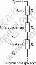
Fig. 1 Equivalent thermal resistance of HP LED package (Rj, Ra, Rh are thermal resistances of LED chip, chip attachment, heat sink, respectively, Ta is temperature of chip attachment)
Phase change heat sink of high power LED makes up of vapor chamber, wick and boiling structure, as shown in Fig. 2. When the heat is applied, the refrigerant at the location immediately vaporizes, and the vapor rushes to fill the vacuum. When vapor comes into contact with condenser surface, vapor releases its latent heat of vaporization and turns into liquid. Then the condensed liquid returns to the heat source via capillary action or natural circulation. Higher effective thermal conductivity is obtained due to the high latent heat of a liquid during phase change.
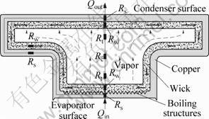
Fig. 2 Schematic diagram of phase change heat sink structure and working principle (Rs, Rw, Rt, Rc are thermal resistance of solid wall, wick, liquid vapor interface, vapor core, respectively)
2.2 Fabrication of 3D boiling structure
2.2.1 Forming of spiral circumferential groove
NITESH et al [13] found that micro-grooves, cracks and fins could speed up the vaporization of refrigerant, so the boiling performance could be improved significantly. TANG et al [14-16] investigated the processing methods of micro-grooves, cracks and fins to improve the heat transfer performance. In this study, spiral micro-groove along circumferential direction was fabricated by ploughing-extrusion (P-E).
The experiment was carried out on the lathe C6132A1, and the red copper column with diameter of 10 mm, thickness of 1 mm was used as the work-piece. P-E tool was made of W18Cr4V, and was composed of a ploughing edge, a primary extrusion face Aγ, a minor extrusion face Aγ′, a primary forming face Aβ and a minor forming face Aβ′ (Fig. 3(a)). The P0-P0 cross-section of the tool is a wedge structure, whose front end is the ploughing blade which ploughs the metal and makes the metal flow along the major extrusion face and the minor one.
The work piece was fixed on the chuck firstly, and P-E tool was installed by way of parallel with copper columnar axis (Fig. 3(b)). After the radial feed parameter of P-E processing was adjusted, the lathe was started to work, so the rotating basic shaft took the work piece to make the rotary motion. SEM image of micro-grooves and fins when P-E depth ap was 0.3 mm and P-E interval dp was 1.24 mm is shown in Fig. 3(c).
P-E speed was continuously changed during forming process of boiling structure. The value of P-E speed was the maximum when process was beginning. When P-E tool was closed to the center of the work piece gradually, the P-E speed reduced synchronously. The relations of the d, f and n must be calculated as
 (2)
(2)
where vP-E is processing speed; t is time; n is rotational speed; f is amount of feed.
2.2.2 Forming of radial grooves
Radial grooves were processed by punch method based on the circumferential grooves. Firstly, workpiece was fixed on the plate, and installation direction of stamping tool was parallel with axial direction of workpiece. Secondly, stamping tool moved downward to punch the workpiece to achieve a radial micro-groove after stamping depth ac was confirmed. Thirdly, stamping tool moved upward while the plate was rotated a certain angle θc, and another radial micro-groove was achieved when stamping tool punched the workpiece again. So, included angle between two micro-grooves was equal to rotated angle of plate, and one end of the two grooves was coincidence on the center of workpiece (Fig. 4(a)).
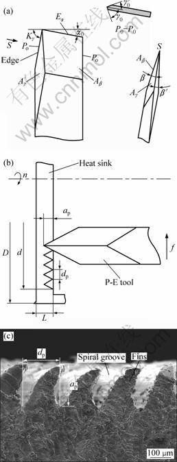
Fig. 3 P-E tool (a), forming schematic diagram by P-E processing (b), SEM image of micro-grooves and fins (c) (α0―Tool clearance of P-E tool; Kγ―Edge inclination angle; γ0―Primary extruding angle; γ0′―Minor extruding angle; β―Primary forming angle; β′―Minor forming angle; Aγ―Primary extrusion face; Aγ′―Minor extrusion face; Aβ―Primary forming face; Aβ′―Minor forming face; D―Small end diameter of phase change heat sink; d―Maximal diameter of processing; ap―P-E depth; dp―P-E interval
When stamping depth ac was 0.3 mm and angle θc was 2°, 3D boiling structure with micro-grooves and fins on the surface which could improve the boiling performance of refrigerant significantly was obtained after workpiece was processed (Fig. 4(b)). The structure interconnected the radial and circumferential grooves and was conducive to flow of liquid from radius to center on evaporating surface.
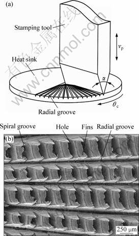
Fig. 4 Forming schematic diagram by punch processing (a), SEM image of 3D boiling structure (b) (α―Blade angle; θc―Angle of rotation; vp―Stamping velocity)
Interference occurred between two adjacent grooves near the center of workpiece in stamping process because there was a certain width of grooves, and the length of interference was relation to the angle θc. Defining Li is the length of interference, so the relations of the Li and θc must be met
 (3)
(3)
where ac is stamping depth, α is blade angle.
2.3 Fabrication of wick
Wick which provided cycle power of refrigerant was a sintering layer on internal face of heat sink by metal powder or fiber [17-18], and there was a promising application due to the porous structure, high porosity and large specific surface area. Experiment was carried out under the protective atmosphere of hydrogen. Wick was fabricated in the temperature range of 900-950 °C and sintered time was 45 min (Fig. 5(a)). Phase change heat sink was obtained eventually (Fig. 5(b)). The porosity (E) of wick can be calculated by the following equation:
 (4)
(4)
where m is the mass of wick; ρ is the density of copper powder; V is the volume of wick.
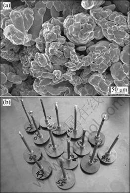
Fig. 5 SEM image of wick (a) and photo of phase change heat sink (b)
3 Testing system of high power LED
The testing system included heater, cooler and temperature data collector. The solid copper embedded one resistor of 100 Ω was used as heat source. The heat generated from resistor could be regulated by a voltage regulator. To improve the accuracy of experimental data, the solid copper and heat sink were wrapped with asbestos tightly. Meanwhile, an aluminum radiator was installed on condenser for cooling by natural convection. Two contact surfaces were polished and coated with thermal silica and then radiator was fastened on the condenser mechanically to reduce contact resistance between radiator and condenser.
Eight thermocouples were distributed on the evaporator (T1, T2, T3, T4) and the condenser (T5, T6, T7, T8). Temperature signal was transmitted to ADAM-4520 from ADAM-4018 which was connected with the eight K type thermocouples, and then to computer whose signal sampling frequency was 1 Hz. The testing system and location of thermocouples are shown in Fig. 6.
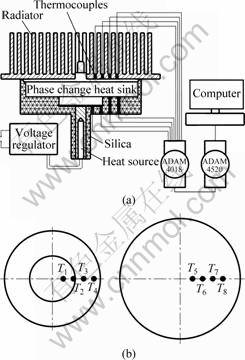
Fig. 6 Performance test system of phase change heat sink (a) and location of thermocouples (b)
4 Results and discussion
4.1 Effect of power on performance
The heat transfer performance of phase change heat sink was tested under the conditions of 3, 5 and 10 W as input powers respectively and water as refrigerant (Fig. 7). It is indicated that the balance time was short, the rise speed of temperature was quick and balance temperature was increased with input power added. The balanced time and the lowest temperature on condenser were 60, 48, 30 min and 38.6, 53.8, 84 °C, respectively. Because less heat was generated under a small input power and some of heat was absorbed by testing system, the rate of heat exchange was small between radiator and air when heat was transferred to radiator by phase change heat sink. After input power was increased, more heat was generated to accelerate the heat exchange between radiator and air, so the balance time was short.
4.2 Effect of refrigerant on performance
Heat transfer characteristics of heat sink could be reflected by thermal resistance. Thermal resistance can be calculated according to the average temperature of evaporator and condenser:
 (5)
(5)
where Tevp-ave and Tcond-ave are average temperatures of evaporator and condenser, respectively.
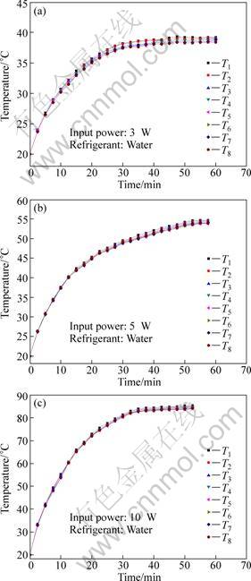
Fig. 7 Temperature distribution of phase change heat sink under different thermal loads: (a) 3 W; (b) 5 W; (c) 10 W
Thermal resistance of heat sink is shown in Fig. 8 under different refrigerants and thermal loads. When the input power increased, temperature of evaporator rose, but thermal resistance decreased. Thermal resistance with water as refrigerant was greater than that with alcohol as refrigerant when input power was 3 or 5 W, and was equal when input power rise to 7.5 W for those with different refrigerants. The reverse was the case of 10 W input power. Water requires more heat to boiling than alcohol due to the higher specific heat capacity and boiling point of water in vacuum than alcohol. Little heat was generated when input power (less than 7.5 W) was small, so lower temperature difference between evaporator and condenser with water as refrigerant led to larger thermal resistance. But in the high input power (greater than 7.5 W), water and alcohol could evaporate quickly. More latent heat was carried off and released by water, so higher temperature difference was obtained, leading to lower thermal resistance. The highest temperatures were 85.4 and 86.8 °C with water and alcohol as refrigerants respectively under the condition of input power for 10W at ambient temperature of 20 °C, and the minimum thermal resistance was 0.09 °C/W. So the low thermal resistance could be achieved in the case of alcohol as refrigerant under the low input power, but water as refrigerant was more suitable for large heat density of heat transfer.
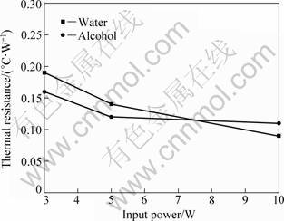
Fig. 8 Thermal resistance of phase change heat sink under different refrigerants
5 Conclusions
1) A novel phase change heat sink was designed and fabricated for packaging cooling of high power LED. The technology of phase change heat transfer was used in packaging cooling and it provides a new way to resolve the thermal problem of packaging level for high power LED.
2) Spiral micro-groove was fabricated by P-E to achieve the circumferential passage of refrigerant. 3D boiling structure with micro-grooves, cracks and fins on the evaporator surface was obtained after radial micro-grooves were formed by stamping based on the spiral micro-groove to achieve the radial passage of refrigerant. Wick was fabricated by sintering of copper powder to provide the capillary force of refrigerant cycle.
3) Phase change heat sink has a good performance of heat transfer with alcohol as refrigerant under the low input power, or water as refrigerant under the high input power. The minimum thermal resistance and the highest temperature are 0.09 °C/W and 86.8 °C under input power of 10 W at ambient temperature of 20 °C.
References
[1] STEIGERWALD D A, BHAT J C, COLLINS D, FLETCHER R M, HOLCOMB M O, LUDOWISE M J, MARIN P S, RUDAZ S L. Illumination with solid state lighting technology [J]. IEEE Journal on Selected Topics in Quantum Electronics, 2002, 8(2): 310-320.
[2] KIM A Y, GOTZ W, STEIGERWALD D A, WIERER J J, GARDNER N F, SUN J, STOCKMAN S A, MARTIN P S, KRAMES M R, KERN R S, STERANKA F M. Performance of high-power AlInGaN light emitting diodes [J]. Physica Status Solidi, 2001, 188(1): 15-21.
[3] NARENDRAN N, GU Y, FREYSSINIER J P, YU H, DENG L. Solid-state lighting: Failure analysis of white LEDs [J]. Journal of Crystal Growth, 2004, 268(3-4): 449-456.
[4] ADAM C, SAMUEL G. Thermal effects in packaging high power light emitting diode arrays [J]. Applied Thermal Engineering, 2009, 29(2-3): 364-371.
[5] NARENDRAN N, GU Y. Life of LED-based white light sources [J]. IEEE Journal of Display Technology, 2005, 1(1): 167-171.
[6] VASILIEV L L. Micro and miniature heat pipes-electronic component coolers [J]. Applied Thermal Engineering, 2008, 28(4): 266-273.
[7] LIU Sheng, YANG Jiang-hui, GAN Zhi-yin, LUO Xiao-bing. Structural optimization of a microjet based cooling system for high power LEDs [J]. International Journal of Thermal Sciences, 2008, 47(8): 1086-1095.
[8] TANG Yong, XIANG Jian-hua, ZHOU Wei, WU Lei. A novel miniaturized loop heat pipe [J]. Applied Thermal Engineering, 2010, 30(10): 1152-1158.
[9] LU Xiang-you, HUA Tse-chao, LIU Mei-jing, CHENG Yuan-xia. Thermal analysis of loop heat pipe used for high-power LED [J]. Thermochimica Acta, 2009, 493(1-2): 25-29.
[10] LAN K, JONG H C, SUN H J, MOO W S. Thermal analysis of LED array system with heat pipe [J]. Thermochimica Acta, 2007, 455(1-2): 21-25.
[11] WENG Chun-jen. Advanced thermal enhancement and management of LED packages [J]. International Communications in Heat and Mass Transfer, 2009, 36(3): 245-248.
[12] XIANG Jian-hua, YE Bang-yan, TANG Yong, ZHOU Wei, HU Zhi-hua. Forming technology of boiling structure on evaporation surface of phase-change heat sink for high-power light emitting diode [J]. Journal of Central South University of Technology, 2010, 17(3): 544-548.
[13] NITESH D N, SUSHIL H B, RICHARD C J. Effect of nucleation site spacing on the pool boiling characteristics of a structured surface [J]. International Journal of Heat and Mass Transfer, 2006, 49(17-18): 2829-2839.
[14] TANG Yong, CHI Yong, WAN Zhen-ping, LIU Xiao-kang, CHEN Jin-chang, DENG Xue-xiong, LIU Li. A novel finned micro-groove array structure and forming process [J]. Journal of Materials Processing Technology, 2008, 203(1-3): 548-553.
[15] XIANG Jian-hua, TANG Yong, YE Bang-yan, ZHOU Wei, YAN Hui, HU Zhi-hua. Compound forming technology of outside 3D integral fin of copper tubes [J]. Transactions of Nonferrous Metals Society of China, 2009, 19(2): 335-340.
[16] TANG Yong, XIA Wei, LIU Shu-dao, ZENG Zhi-xin, YE Bang-yan. Fin formation model during pre-roll ploughing of copper 3D outside fin tube [J]. Transactions of Nonferrous Metals Society of China, 2001, 11(5): 712-716.
[17] ZHOU Wei, TANG Yong, PAN Min-qiang, WEI Xiao-ling, CHEN Hong-qing, XIANG Jian-hua. A performance study of methanol steam reforming microreactor with porous copper fiber sintered felt as catalyst support for fuel cells [J]. International Journal of Hydrogen Energy, 2009, 34(24): 9745-9753.
[18] AHMED Y M Z, RIAD M I, AHLAM M K, SHALABI M E H. Correlation between factors controlling preparation of porous copper via sintering technique using experimental design [J]. Powder Technology, 2007, 175(10): 48-54.
大功率发光二极管相变热沉的制造及测试
向建化1,张春良1,江 帆1,刘晓初1,汤 勇2
1. 广州大学 机械与电气工程学院,广州 510006;
2. 华南理工大学 机械与汽车工程学院,广州 510640
摘 要:制造一种新型大功率发光二极管(LED)相变热沉作为封装级散热元件,采用犁切-挤压成形的周向螺旋状微沟槽和采用冲压成形的放射状径向沟槽组成的三维结构作为蒸发面强化沸腾结构,内壁采用铜粉颗粒烧结而成的毛细芯结构为工质提供循环动力。测试了相变热沉在不同输入功率和工质条件下的运行特性。结果表明,相变热沉具有良好的传热能力,在环境温度为20 °C,输入功率为10 W的条件下,相变热沉最高温度为86.8 °C,可满足功率为10 W的LED封装散热需求。
关键词:大功率发光二极管;相变热沉;强化沸腾;毛细芯;传热性能
(Edited by LI Xiang-qun)
Foundation item: Projects (50436010, 50930005) supported by the National Natural Science Foundation of China; Project (U0834002) supported by the Joint Fund of NSFC-Guangdong of China
Corresponding author: TANG Yong; Tel/Fax: +86-20-87114634; E-mail: ytang@scut.edu.cn
DOI: 10.1016/S1003-6326(11)60974-6

