J. Cent. South Univ. Technol. (2011) 18: 1413-1417
DOI: 10.1007/s11771-011-0855-7
Features of pipe transportation of paste-like backfilling in deep mine
WANG Xin-min(王新民)1, ZHAO Jian-wen(赵建文)1, XUE Jun-hua(薛俊华)2, YU Guo-feng(余国锋)2
1. School of Resources and Safety Engineering, Central South University, Changsha 410083, China;
2. Huainan Mining (Group) Co., Ltd., Huainan 232001, China
? Central South University Press and Springer-Verlag Berlin Heidelberg 2011
Abstract: Based on the pipe transportation of paste-like backfilling system of a certain deep coal mine, its dynamics process was simulated and analyzed. A two-dimensional dynamic model of extraordinary deep and lone pipe was built by GAMBIT, on the basis of which the simulation was done by implicit solver of FLUENT 2ddp. The results show that hydraulic loss of pipe transportation is less than the pressure produced by gravity, which means the backfilling material can flow by itself. When the inlet velocity is 3.2 m/s, the maximum velocity of 4.10 m/s is at the elbow and the maximum velocity in the horizontal pipe is 3.91 m/s, which can both meet the stability requirement. The results of the simulation are proved to be reliable by the residual monitor plotting of related parameter, so it can be concluded that the system of pipe transportation is safe.
Key words: backfilling; deep mine; paste-like slurry; pipe transportation; flow
1 Introduction
With the depletion of shallow resources, mines are being explored deeper and deeper. For example, the depths of several huge coal mines of Huainan Mining Group have exceeded 700 m and the depths are close to or even larger than 1000 m [1] in Xinkuang Mining Group, the second mining area of Jinchuan Non-ferrous Mine, Dongguashan Copper-sulphide Mine and Gaofeng Mining Limited Corporation. Backfilling method is a most widely used method in deep mines. Nevertheless, in deep mines, pipe abrasion, blocking or even explosion is always presented to bring about the system failure because of the fast velocity or high pressure caused by the large elevation difference and ratio of total length to vertical height of pipeline (L/H ratio). So, it is necessary and important to analyze the condition of underground pipe transportation.
In shallow mines, the parameters related with two-phase flow transportation almost lie on a number of empirical formulas [2-3]. However, the researches on the features of pipe transportation in deep mines are rare. Flow velocity and rheological behavior of pipeline transportation filling slurry were forecast by mathematic methods [4-5]; long distance gravity pipeline transportation was studied by rheological tests with Capillary Rheometer [6]; rheological characteristics of high pressure pipeline transportation were tested by self-developed tube type pressure rheological test facility [7]. Besides, industrial tests were much more used to determine the mechanical parameters of pipeline transportation backfill slurry and the security of the system [8]. External factors should be considered in these research approaches, which are not thorough for relatively complicated non-linear flow phenomena. And the research results can be limited, which only fit for some special systems. Features of pipe transportation filling slurry cannot be reflected systematically and intuitionistically and these approaches must not be extended to extraordinarily long transportation pipelines.
The development of computer technology provides the numerical simulation method for pipeline transportation. At present, the most widely used soft-wares are FLOW-3D, FLUENT, and ANSYS. For example, FLOW-3D was used to analyze the properties of hydraulic transportation [9]. ANSYS was applied to simulate and analyze paste-like backfilling pipe transportation [10]. FLUENT was usually adopted in aerospace, automotive design, oil and gas, turbine design and so on for its abundant physical models and advanced numerical algorithms. There are utilizations in pipe transportation as well: simulation of siphon tow-phase flow [11], study on factors of turbulence intensity [12]; numerical simulation of T-junction pipe transportation [13]; computation of hydraulic performance of viscous oil on the centrifugal pump [14]. Unfortunately, the research on extraordinary long pipeline is rather rare.
In this work, the dynamics performance of two-phase flow transportation in deep mine was presented by FLUENT, the major behavior and parameter of the transported slurry were analyzed qualitatively and quantitatively, and the theoretical basis and practical implement schemes were also brought up for filling system design in deep mines.
2 Two-dimensional dynamic model of paste- like pipeline transportation
The research is mainly based on the engineering case of the backfilling pipeline transportation in a certain deep coal mine, which is an extraordinary long past-like gravity backfilling system. The ground surface is 637 m (H) higher than the underground shaft and 2 470 m higher than the stope. The backfilling technique of the mine is a coal gangue paste-like gravity backfilling; the filling aggregate is coal gangue; the binder is concrete and coal ash; the mass proportioning of the slurry is 1:4:15 of concreter:coal ash:coal gangue; the mass fraction of backfilling slurry is 70%; the volume fraction and the density of backfilling slurry are 47.3% and 1.76 t/m3, respectively.
2.1 Rheological model
The inner structure of paste-like filling slurry is strong and the initial shear stress is large. As a result, the Bingham model is used as the rheological model. The indoor verification results are recorded in Table 1.
Table 1 Indoor verification results
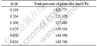
The regression analysis of the data in Table 1 proves that the shear stress τ and shear rate dγ/dt are linearly dependent. Accordingly, the rheological model is Bingham model, and it meets the following equation:
τ=117.730 6+4.616 8 dγ/dt (1)
2.2 Basic hypotheses
The complicacy of pipeline transportation techniques and mechanics makes it impossible to get the exact solution currently. For the convenience of simulation and analysis, hypotheses are assumed as follows:
1) Viscous slurry is with constant viscosity, which would not change with temperature and time;
2) Slurry works as Bingham body and is assumed to be incompressible;
3) Heat exchange is not considered;
4) The influence of libration, geopressure and so on is ignored;
5) The transportation pipe is full of slurry at the initial stage of the simulation.
2.3 Determinations of model parameters
1) Initial velocity of slurry (ν)
The flow of slurry (Q) at the filling station is 200 m3/h. The pipe is seamless steel, internal diameter (D) of which is 0.152 m. The inlet velocity of the slurry can be calculated. To make the computation easier, here the inlet velocity of the slurry is approximated to be 3.2 m/s.
 3.06 m/s (2)
2) Viscosity
The viscosity of slurry can be measured by NDJ-1B rotational viscometer. The instrument is driven by the motor which makes the rotor rotate at constant speed, and the viscous torque can be detected by the sensor on the rotor. So, the viscosity can be calculated by computer processing. Here, the viscosity is 0.3 Pa・s.
3) Equivalent roughness height and wall roughness coefficient [15]
The roughness of pipe affects the resistance of pipes, so it is necessary to take the roughness of pipeline into account. The paste-like backfilling pipe is seamless, and the equivalent wall roughness height is 0.032 5 mm, which denotes the actual roughness. Pipe roughness height, rough shape and distribution are irregular, and wall roughness coefficient is assumed to be 0.12.
4) Reynolds number
Reynolds number can be used to characterize different flow regimes, such as laminar or turbulent flow. Laminar flow occurs when Reynolds number (Re) is smaller than 2 300, while turbulent flow occurs at high Reynolds number which is higher than 4 000 and between the two states is the transitional flow where turbulence flow can change into laminar flow with the external conditions and vice versa. Different definitions of Reynolds number for non- Newtonian fluid in circular pipes are proposed with varied purposes according to different objects [16]. In this work, the definition of Reynolds number is based on effective viscosity formula:
 (3)
(3)
where ρ is the density of slurry, v is the initial velocity, here v=3.2 m/s, and μ denotes the viscosity, here μ= 0.3 Pa・s.
Reynolds number is larger than 2 300, so the flow regime is turbulent flow.
2.4 Two-dimensional dynamic model
1) Two-dimensional model building
The geometry model was built by BAMBIT and 2D model was built for the limitation of FLUENT and complicated conditions of pipeline transportation, as shown in Fig.1.

Fig.1 Geometry model of backfilling pipe
The vertical section of transportation system is 673 m long, the level section is 2 470 m long, L/H ratio is 4.67, the inner pipe diameter is 0.152 m, and there is a right angle connection with a radius of 0.38 m.
2) Generation of mesh
The quality of grids affects the accuracy of follow- up results. As the length of the pipeline is 3 143 m and the diameter is 0.152 m, the simulated pipe falls into the category of long pipeline. Too dense or too sparse grids could produce too large deviation of computed results: too sparse grid could increase the discretization deviation; too dense grids could multiply discrete points and lead to the enlargement of rounding [17].
After numerous experiments and comparison, the model was divided into five parts: inlet, vertical section, elbow section, horizontal section, and outlet. The inlet and outlet parts were meshed into 100 equal intervals; the parts 10 m from the inlet and outlet were both divided into 100 parts equally; pipes 5 m from the elbow vertically and horizontally were separated to unvarying 100 parts; vertical and horizontal sections left included 658 and 2 455 equal intervals separately and the total grids were 341 300.
2.5 Boundary conditions
When model was set and ideal mesh was generated, boundary conditions were still needed to be defined:
1) Inlet was defined to be VELOCITY_INLET, here it was 3.2 m/s;
2) Outlet was defined to be OUTFLOW;
3) Wall was defined to be WALL, wall roughness height was defined to be 0.000 032 5 m, and wall roughness coefficient was defined to be 0.12.
As the model had a typical slender geometry and the filling slurry was at a constant speed, the simulation was done by double-precision quantity implicit solver Fluent 2ddp. The acceleration of gravity was also added.
3 Results and analysis
3.1 Monitoring of results
In order to judge the convergence of computing, it is essential to monitor the residuals. However, wrong conclusion might be gained when only judging by the residuals method. Therefore, the entire data of all relevant variables are monitored and the inflow and outflow material and energy are checked by conservation law.
It can be seen from Fig.2 that, although testing values of each variable exhibit oscillating at the initial stage of simulation, they all tend to be convergent after 926 times iterative computations and the convergence monitoring curves are leveling off. All these prove that the simulation results are more reliable.
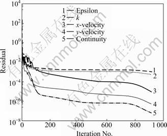
Fig.2 Residuals of variables
3.2 Analysis of flow velocity
The velocity gradient exists along the pipeline cross-section. The maximum velocity is at the axis of pipe and the distribution is approximately parabola. On the cross-section of elbow, velocity gradient becomes more visible and the pipe flow velocity is gradually increased from the outside to the inside of pipe (Fig.3). The velocity turns to be lower when the flow reaches the outlet (Fig.4). For the reason of gravity, the velocity gradient of horizontal pipe offsets to the lower side of the wall (Fig.5).
The maximum velocity along the pipeline is 4.10 m/s, which is located at the elbow of the pipe. The maximum value along the horizontal pipe flow is 3.91 m/s. According to the experience of South Africa mine filling, the working velocity of horizontal pipe should not exceed 4 m/s, because the wear rate on the horizontal pipe grows more considerably as the working velocity gets larger. The horizontal pipe working velocity is no more than 4 m/s, implying that the system is reliable in its economy.
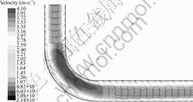
Fig.3 Velocity distribution at elbow
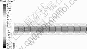
Fig.4 Velocity distribution at outlet
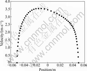
Fig.5 Distribution of velocity on outlet surface
3.3 Analysis of pressure
As the pressure is assumed to be zero in the elbow, the difference between import and export pipeline pressure is the resistance of the whole pipeline. That is to say, the resistance is the difference between the maximum and the minimum of pressure. According to Fig.6, the maximum pressure is 1 820 249 Pa and the minimum pressure is -6 682 104 Pa with a difference of 8 502 353 Pa, namely about 8.50 MPa.
The pressure generated by gravity (p) can be calculated as
p=ρgH=1 760×9.81×673=116 197 488 Pa≈11.6 MPa (4)
where ρ is the density of slurry, here ρ=1 760 kg/m3; g denotes the acceleration of gravity, here g=9.81 m/s.
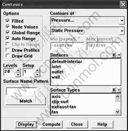
Fig.6 Display of static pressure
The pressure generated by gravity is larger than the pressure loss of 8.50 MPa, indicating that the system is reliable in flowability.
The simulation results show that, the dramatic velocity change and the maximum velocity turn up at the elbow. So, it is the elbow that is prone to be worn, blocked and at last burst, and it is a key part to take effective measures to reduce the pipe wear:
1) The two-step pipeline can be transformed into a multi-step pipeline with the horizontal pipe using reinforced plastic;
2) Pipe diameter may be increased modestly and the telescoped pipeline is suggested [18];
3) Inlet velocity can be reduced appropriately;
4) Quality of steel pipe lining should be improved to protect the pipeline; at the elbow, cross pipe or buffer box with elbow, and other technical measures can be adopted to reduce the pipe abrasion [19].
4 Conclusions
1) An application of FLUENT in deep, long paste-like gravity pipeline transportation was carried on which is provided to be a new design and research idea compared with the previous methods for deep backfilling pipeline transportation systems.
2) Rules of flow in pipeline transportation systems were demonstrated. The slurry velocity shifts dramatically at the elbow, where the maximum velocity occurs, so the elbow is prone to be worn, blocked and burst. Therefore, the vertical and horizontal pipe joints should be highly wear-resistant pipe to enhance the system safety and reliability.
3) When the working velocity of slurry is 3.2 m/s, the maximum horizontal speed is 3.91 m/s, less than 4 m/s on the gravity transport condition; pipeline pressure loss is 8.50 MPa, less than the pressure caused by gravity (11.62 MPa), illustrating that the pipeline transportation system is safe and reliable.
References
[1] SHI Yun-yu. Concern of splendor―The investigation report from China mine [J]. The Ministry of Land and Resources, 2005, 2: 6-17. (in Chinese)
[2] LILei, USUIH, SUZUKIH. Study of pipeline transportation of dense fly ash-water slurry [J]. Coal Preparation, 2002, 22(2): 65-80.
[3] WANG Pei-Xun. Computation of filling waterpower grade in mines [J]. Nonferrous Metals, 2003, 32(1): 8-11.
[4] NI F, ZHAO L, MATOUSEK V. Two-phase flow of highly concentrated slurry in a pipeline [J]. Journal of Hydraulics: Series B, 2004, 16(3): 325-331.
[5] HU Hua, SUN Heng-hu, HUANG Yu-cheng, YANG Bao-gui. Rheological model and equation of viscoelastic-plasticity of paste-like backfill pulp[J]. Journal of China University of Mining & Technology, 2003, 32(2): 119-122.
[6] ZHENG De-xue. Study on the application of long distance gravity transportation of copper concentrate[J]. Metal Mine, 2002(1): 43-45. (in Chinese)
[7] WANG Xin, ZHAO Xue-yi. Experimental research on particle characteristics and rheological properties of high concentration red mud[J]. Metal Mine, 2008(1): 107-134. (in Chinese)
[8] WANG Xin-min, ZHANG Qin-li. Half technical test scheme of preparation and transportation of paste-like slurry backfilling of coal refuse [R]. Changsha: Central South University, 2005. (in Chinese)
[9] WANG Xin-min, DING De-qiang, WU Ya-bin, ZHANG Qin-li, LU Yang-zhe. Numerical simulation and analysis of paste backfilling with piping transport [J]. China Mining Magazine, 2006, 15(7): 57-66. (in Chinese)
[10] GONG Zheng-guo. Numerical analysis and research of pipeline hydraulic filling features [D]. Changsha: Central South University, 2005: 82-108.
[11] SUPA-AMORNKUL S, STEWARD F R, LISTER D H. Modeling two-phase flow in pipe bends [J]. Journal of Pressure Vessel Technology, 2005, 127(2): 204-209.
[12] JENSEN B B B. Numerical study of influence of inlet turbulence parameters on turbulence intensity in the flow domain: Incompressible flow in pipe system [J]. Professional Engineering Publishing, 2007, 11(4): 23-31.
[13] YANG Kang, LIU Ji-pu, MA Wen-bo. Simulation of turbulence data for T pipe basic on FLUENT software [J]. Chemical Equipment Technology, 2008, 29(4): 33-36.
[14] LI Wen-guang. Performance computations of centrifugal pump handling viscous oils [J]. Drainage and Irrigation Machinery,2008, 29(4): 33-364.
[15] WANG Rui-jin, ZHANG Kai. FLUENT technical base and application examples [M]. Beijing: Tsinghua University Press, 2007: 21-44. (in Chinese)
[16] ZHAO Guo-hua. Simulating and experiment research of resistance characteristics of coal-water-slurry [D]. Nanjing: Southeast University, 2007: 37-38.
[17] PATERSON A J C, COOKE R. Design of hydraulic backfill distribution system-lesson from case Studies Proceeding of the Sixth International Symposium on Mining with Backfill Brisbane [C]// Mine Fill’ I998. Australia, 1998: 225-264.
[18] WANG Xin-min, LU Yang-ze, ZHANG Qing-li. Simulating and optimizing the configuration parameter of stope in plaster-like filling [J]. Chinese Journal of Underground Space and Engineering, 2008, 4(2): 346-350. (in Chinese)
[19] WANG Xin-min. Research on backfilling material and pipe transportation system of deep mines [D]. Changsha: Central South University, 2005, 172-193. (in Chinese)
(Edited by YANG Bing)
Foundation item: Project(2008BAB32B03) supported by the National Science and Technology Pillar Program during the 11th Five-year Plan Period of China
Received date: 2010-07-23; Accepted date: 2010-10-11
Corresponding author: WANG Xin-min, Professor, PhD; Tel: +86-13739056780; E-mail: zhaojianwen0607@qq.com

