
Interfacial structure and joint strengthening in arc brazed galvanized steels with copper based filler
LI Rui-feng(李瑞峰)1, YU Zhi-shui(于治水)2, QI Kai(祁 凯)1
1.Provincial Key Laboratory of Advanced Welding Technology, Jiangsu University of Science and Technology,
Zhenjiang 212003, China;
2.College of Materials Engineering, Shanghai University of Engineering Science, Shanghai 200336, China
Received 8 May 2005; accepted 11 July 2005
Abstract: Galvanized steel sheets were joined by tungsten inert gas(TIG) and metal inert gas(MIG) brazing process using copper based filler. The results show that the joint zone hardness is higher than that of the base material or copper filler from the microhardness tests of TIG brazing specimens, and the fracture spot is at the base materials zone from the tensile tests of MIG brazing specimens. Examination using energy dispersive X-ray analysis reveals the presence of intermetallic compound Fe5Si3(Cu) in the joint. The dispersal of fine Fe5Si3(Cu) particles is the main strengthening factor for the joint. The Fe5Si3(Cu) particles are determined to arise from three sources, namely, spot micro-melt, whisker-like fragmentation and dissolve-separation actions.
Key words: galvanized steels; CuSi3; TIG; MIG; arc brazing; strengthening mechanism; interfacial structure
1 Introduction
Arc brazing is a brazing method that the specimens are heated by arc[1]. It is the generic terms of GMA brazing and GTA brazing[2], and has both the characteristics of brazing and welding. Compared with traditional arc fusion welding, the superiorities are higher mechanical strengths, narrower HAZ area, aesthetic in appearance, surface contamination and metallic surface coating tolerant, practically spatter free, energy conservation and easy to be automated, etc. It has unique merits in joining thin sheets, thermal sensitive and anti-magnetic metal materials. So the arc brazing method has extensive practical applications. Now the research of such technology gets extensive recognitions by researchers at home and abroad[3-6].
Arc brazing of galvanized steel sheets were studied using copper based filler and it is found that the joint strength is higher than that of the base materials[5-8]. Such studies only investigated brazing equipments and processes, but few researchers have given reasons why such high joint strengths can be obtained with arc brazed joints. In this paper, the arc brazing of galvanized steels with CuSi3 as filler material was reported, with particular emphasis on the microstructure and strengthening behavior and mechanisms of the joint.
2 Experimental
2.1 Materials
The experimental base materials were galvanized steel, dimensions 40 mm×40 mm×2 mm for tungsten inert gas(TIG) brazing, and 80 mm×40 mm×2 mm for metal inert gas(MIG) brazing. The filler metal was CuSi3 (Cu 97%, Si 3%, molar fraction) for 200 mg, which was bent into ring form. Both galvanized steel and CuSi3 specimens were cleaned with alcohol and acetone sequentially prior to brazing.
2.2 Methods and procedure
To obtain an interfacial reaction between base material and filler metal, filler metal spreading experiments were conducted on the base metal surface using arc heating, i.e. TIG brazing. To obtain the tensile strength of the joint, MIG brazing was used. In the TIG brazing process, arc currents were 20-80 A with arcing times ranging from 0 s to 5 s and a voltage of 11.1-11.2V.
Each time, 200 mg of brazing filler metal was used, and spread on the surface of the base material. In the MIG brazing process, the arc current was 75 A at a voltage of 19.4 V and a speed of 90 cm/min. Arc brazing was accomplished using a FK-2600 welding machine connected in direct current straight polarity(DCSP) in flowing argon.
Arc brazing specimens for TIG brazing were cut through, mounted, and polished for cross-section area examination. The other groups were metallographically studied via MM-6. The interfacial structure and composition were investigated using a scanning electron microscope JXA 840A and energy dispersive X-ray(EDS) analysis. Components in the region between the brazing filler metal and base material were analyzed by energy spectrometer. Microhardness of the joint sample cross-sections was determined using an M400-H1 microhardness tester(LECO). Microhardness testing procedures followed the ASTM standard test method. All microhardness tests were carried out in areas where the joint zone was about 20 mm with the spacing between indents being at least 60 mm to eliminate possible interference. On each joint cross-section, hardness measurements were made in the filler metal zone and in the base materials away from the filler zone. An average of ten readings was taken at each location. A dwell time of 15 s and a load of 0.098 N were used for the measurement.
Arc brazing specimens for MIG brazing were used for tensile testing to evaluate joint strength. Specimens were mechanized according to ISO standard 5187:1985 for brazing and soldering.
3 Results and analysis
3.1 Tensile test
To measure the standard joint strength, MIG brazing and tensile testing was conducted first. The experiments show that most of the tensile test specimens fractured at the base materials (see the photographs of fractured joints, Fig.1). Fig.1 shows that the strength of the joint zone is higher than that of the base material zone and the CuSi3 filler zone. It is obvious that the joint zone is strengthened.
3.2 Microhardness test
Fig.2 shows the measured microhardness of the joints for different arc times at an arc current of 70 A, and the zero spot is the interface adjacent to the copper filler side. It can be seen that the micohardness is highest at the interface, and the interface zone hardness is higher than that of the copper filler and base material. This observation agrees with the results of the joint tensile test, in that joint zone properties are better than those of the CuSi3 filler zone. On the other hand, it can be seen that the maximum strength of these joint is also different. It is the highest for an arc time of 6 s (210 MPa). It can be concluded that the strengthening effect increases with time. On the base material side, Cu atoms react with Fe, the base material is solution strengthened, so the hardness of the base material near the joint is also higher than that of the base material remainder, as shown in Fig.2.
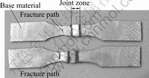
Fig.1 Photo of tensile samples
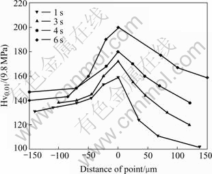
Fig.2 Microhardness distribution in brazing zone at different arcing time(Iarcing=70 A)
3.3 Interfacial structure examination
The cross-sections of all samples processed under different arcing currents for 4 s arcing time were examined by scanning electron microscope(SEM) firstly. Fig.3 shows the cross-section SEM micrographs of specimens prepared at 20, 40, 70 and 80 A, indicating that interface layers are formed at the joint. It can be seen that when the arcing current is relatively small (I=20 A), there are no fine particles in the filler zone. With increasing arcing current, the number of fine particles in the filler metal zone increases. For the same arcing time (4 s), when the arcing current is higher, the particles change from ball-like form to star-like form to flower-like form in turn, and the dimensions of such particles become larger and larger. On the other hand, Fig.3 also shows that many whisker-like intermetallic compounds grow from the interface into the copper zone.
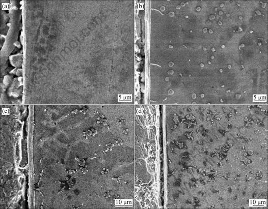
Fig.3 Effect of arcing current on microstructure of brazing joint (tarcing=4 s): (a) 20 A; (b) 40 A; (c) 70 A; (d) 80 A
Fig.4 shows the cross-section SEM micrographs of specimens prepared for 1, 3, 4 and 5 s arcing time at an arcing current of 70 A. There are some similarities between Fig.4 and Fig.3. Fig.4 also shows Fe5Si3(Cu) growing mechanism with increasing time. It can be seen in Fig.4 that Fe-Si compounds nucleate at the interface and first grow in wave-like form into the copper filler zone. Then some of the compounds ‘sprout’, and grow bigger and longer into the copper filler zone. Then these compounds are fragmented by the arc stirring force into block-like form and are distributed there. If they reach their melting temperature in the filler zone, such particles are unlikely to survive long enough to become sources of equiaxed grains until the liquid becomes supercooled unless they are swept into cooler regions by the imposed stirring. In arc brazing, heating and cooling processes occur very quickly. The stirring force of the arc is also strong, so that many particles can be swept into the filler zone and survives there.
In the present study, because the welding machine was connected in DCSP and the melting point of galvanized layer was relatively low(419.5 ℃). When some spot was melted and vaporized, due to the relatively low energy of the arc column, there would be anode spot[9]. During the arc brazing process, it can be seen that there are many ‘high brightness’ spots on the surface of the base material, and these are all anode spots. Iron will also vaporize from the anode spot and migrate, to be distributed throughout the filler metal zone. Fig.4(a) shows that at the start there are already many particles in the filler zone, and it can be concluded that these particles come from the anode spot action of the arc.
3.4 EDS analysis
To confirm the atomic composition of the flower (star)-like compounds in the filler zone, an energy dispersive X-ray analysis was conducted (Fig.5). Fig.5(a) shows a magnified micrograph of Fig.4(c), and Fig.5(b) shows the results of spot EDS analysis of the flower-like compound. It can be seen that the molar ratio of Fe to Si is 5:3, so the flowerlike particles in the copper zone are Fe5Si3(Cu) intermetallic compound. In addition, the EDS results of whisker-like, ball-like and star-like compounds show that all the molar ratios of Fe to Si are 5:3; and they are must be Fe5Si3(Cu) intermetallic compounds.
4 Discussion
It can be concluded from joint microstructures, joint tensile tests and hardness measurements, as well as EDS analysis that a large number of Fe5Si3(Cu) particles have migrated to the copper filler zone and dispersed in it. The high strength of the joint mainly results from these fine particles dispersed in the copper filler metal zone. There are three sources of such particles as follows.
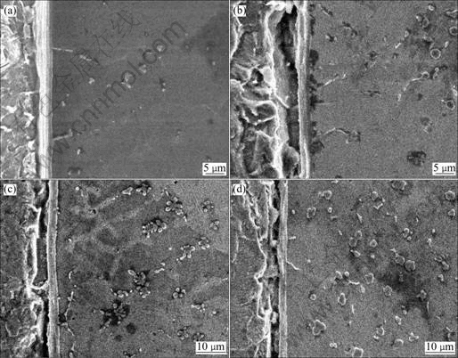
Fig.4 Effect of arcing time on microstructure of brazing joint(Iarcing=70 A): (a) tarcing=1 s; (b) tarcing=3 s; (c) tarcing=4 s; (d) tarcing=5 s
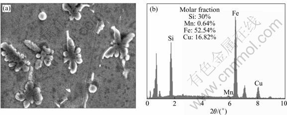
Fig.5 Fe5Si3(Cu) microstructure and EDS analysis (Iarcing=70 A, tracing=4 s): (a) Microstructure; (b) EDS result
1) Due to the anode spot action of the arc, craters will form on the galvanized steel surface. Thus some iron particles are vaporized from the galvanized steel surface due to the transient arc heating. Then the strong stirring and flow forces of the arc sweep the iron particles into the copper filler zone[10]. When the Fe content is more than the solubility of Fe in Cu, they will in situ-solidify and react with the silicon. This is the first source of intermetallic compound Fe5Si3(Cu), and is termed ‘spot micro-melt’ action.
2) Due to the rapid arc heating, CuSi3 filler melts very quickly after turning the power on. In contact with liquid copper, the steel surfaces in the heating area dissolve little. The longer the joining time is, the greater the dissolution of steel is in the liquid copper, until saturation is reached[11]. So there must be some fine Fe particles dissolve in the copper filler zone, in accordance with fusion welding[12, 13]. When the Fe content is more than the solubility of Fe in Cu, then they will react with silicon. This is the second source of intermetallic compound Fe5Si3(Cu), named dissolve-separation action.
3) At the beginning, the reaction is as described in part 2). As time passes, it can be seen that at the interface whisker-like compounds grow from the top of the wave-like interface into the copper filler zone due to the rapid heating and cooling effects of arc brazing. The EDS analysis of such particles shows they are also Fe5Si3(Cu). Due to the stirring force of the arc and the sweeping force of liquid flow at the solid/liquid interface, these whisker compounds become fragmented into block form at the top. They then migrate to the liquid filler zone due to the liquid flow force. The block form compounds change to ball form (less surface energy) and grow when they reach the centre of the liquid filler zone. The survival or melting of compounds depends on the temperature of the liquid. Due to the rapid heating and cooling by the arc, there is no congregation of the melt, and there is great supercooling in the liquid filler zone. Thus most of the particles in the filler zone will survive. If they stay at the zone with the temperatures higher than the liquidus curve for a while, they will melt. If the compounds survive in the filler zone, then they will grow into star-like intermetallic compounds, as shown in Figs.3 and 4. The compounds then will concentrate, grow into flower-like form, disperse and solidify in the filler zone: the growth mechanism of the compound is Ostwald ripening[14, 15]. Finally, when the quantities and dimensions of ball-like and star-like intermetallic compounds reach a satisfactory level of dispersal in the copper filler zone, the joints is strengthened. This is the third source of intermetallic compound Fe5Si3(Cu), named ‘whisker fragmentation’ action.
5 Conclusions
Interfacial structure, tensile tests, microhardness measurements and EDS analysis of arc brazed galvanized steel using CuSi3 filler has been described. The primary conclusions are:
1) Tensile tests and microhardness tests across joint zone polished cross-sections indicate that the strength and microhardness in the interface are greater than those of the base materials and CuSi3 filler metal zone. Elemental analysis by energy dispersive X-ray analysis reveals the presence of intermetallic compounds Fe5Si3(Cu) in the joint.
2) The high joint strength obtained in this study is due to the formation and dispersal of intermetallic compound Fe5Si3(Cu) in the joint zone.
3) The intermetallic compound Fe5Si3(Cu) has three different sources, namely, spot micro-melt, dissolve separation and whisker-like fragmentation actions.
References
[1] The Chinese Mechanical Engineering Society. Welding Association. Welding Dictionary [M]. Beijing: Mechanical Engineering Press, 1998. 265.
[2] Draugelates U, Bouaifi B, Helmich A, OUALSSA B, BARTZSCH J. Plasma-arc brazing: A low-energy joining technique for sheet metal[J]. Welding Journal, 2002, 3: 38-42.
[3] Fujii H, Shiraki A. Development of arc-brazing welding method and application of pulsed MIG welding to various thin plates[J]. National Technical Report, 1997, 23(2): 23-31.
[4] Kazuyoshi S, Kazutoshi N. Recent trends and future development of interfacial joining processes[J]. Journal of Japan Weld Society, 2003, 72(1): 31-39.
[5] YU Z S, QIAN Y Y, LI R F, ZHOU F M. Surface wetting and interfacial behavior in arc brazing for titanium alloy[J]. Materials Science and Technology, 2003, 10: 1399-1402.
[6] Bouaifi B. Low-heat process enhance jointing of coated sheet metals[J]. Welding Journal, 2003(1): 26-31.
[7] Ebbinghaus M, Prinz H D. Arc brazing of steel components with copper based filler metal[J]. DVS Report, 1998, 192:146-149.
[8] Bouaifi B, Ousaissa B, Helmich A. Plasma arc brazing in sheet metal construction[J]. Science and Technology of Welding and Joining, 2002, 7: 326-330.
[9] Lancaster J F. The Physics of Welding[M]. London: Pergamon Press, 1986. 8.
[10] Zhong Y B, Ren Z M, Sun Q X, JIANG Z S, DENG K, XU K D. Behavior of particles in front of metallic solid/liquid interface in electromagnetic field[J]. Trans Nonferrous Met Soc China, 2003,13(4): 755-763.
[11] Lindner r, Karnik f. Diffusion of Molten Copper and Solid Iron[J]. Acta Met, 1995, 43(3): 297-303.
[12] Li J H, Lin R Y. Joint zone evolution in infrared bonded steels with copper filler[J]. Metall Mater Trans B, 2001, 32B: 1177-1183.
[13] Munitz A, Elderandall S P, Abbaschian R. Metal liquid phase separation in tungsten Inert gas and electron beam copper/stainless-steel welds[J]. Journal of Materials Science, 1995, 51(30): 2901-2910.
[14] Elder k r, Grant m, Guo h. Theory and simulation of Ostwald ripening[J]. Phys Rev B, 1993, 50: 14110-14124.
[15] Stefanescu d m. Science and Engineering of Casting Solidification[M]. New York: Kluwer Academic Publishing House, 2002. 213-221.
Foundation item: Project (50475051) supported by the National Natural Science Foundation of China
Corresponding author: LI Rui-feng; Tel:+86-511-4401187; E-mail: lrfzj7912@163.com
(Edited by LI Xiang-qun)

