有限元模拟预测AA6111合金半连续铸件的热裂敏感性
来源期刊:中国有色金属学报(英文版)2020年第12期
论文作者:陈东旭 豆瑞峰 韩加强 王俊升
文章页码:3161 - 3172
关键词:汽车轻量化;AA6111合金;半连续铸造;热裂判据;孔隙分数;有限元模拟
Key words:vehicle light-weighting; AA6111 alloy; direct chill casting; hot tearing criterion; pore fraction; finite element simulation
摘 要:为了预测凝固过程中的热裂敏感性(HTS)并提高铝合金铸件的质量,采用直接有限元(FE)方法建立AA6111的本构方程。通过有限元模型和热撕裂准则的耦合,建立用于工业AA6111合金半连续铸造的热撕裂模型。将此模型应用于实际制造过程,表征铸造速度、底部冷却、二次冷却以及几何形状变化对HTS的影响。结果表明,铸坯的HTS随着速度和铸坯半径的增大而增加,而随着底部界面传热系数或二次水冷却速率的增大而降低。该模型展示出在模拟热裂引发时结合最大孔隙率的能力,这将对优化铸造条件和化学成分以达到HTS最小化从而控制铸造质量产生重大影响。
Abstract: To predict hot tearing susceptibility (HTS) during solidification and improve the quality of Al alloy castings, constitutive equations for AA6111 alloys were developed using a direct finite element (FE) method. A hot tearing model was established for direct chill (DC) casting of industrial AA6111 alloys via coupling FE model and hot tearing criterion. By applying this model to real manufacture processes, the effects of casting speed, bottom cooling, secondary cooling, and geometric variations on the HTS were revealed. The results show that the HTS of the billet increases as the speed and billet radius increase, while it reduces as the interfacial heat transfer coefficient at the bottom or secondary water-cooling rate increases. This model shows the capabilities of incorporating maximum pore fraction in simulating hot tearing initiation, which will have a significant impact on optimizing casting conditions and chemistry for minimizing HTS and thus controlling the casting quality.
Trans. Nonferrous Met. Soc. China 30(2020) 3161-3172
Dong-xu CHEN1, Rui-feng DOU2, Jia-qiang HAN2, Jun-sheng WANG1,3
1. School of Materials, Beijing Institute of Technology, Beijing 100081, China;
2. School of Materials Science and Engineering, University of Science and Technology Beijing, Beijing 100083, China;
3. Advanced Research Institute of Multidisciplinary Science, Beijing Institute of Technology, Beijing 100081, China
Received 5 April 2020; accepted 15 November 2020
Abstract: To predict hot tearing susceptibility (HTS) during solidification and improve the quality of Al alloy castings, constitutive equations for AA6111 alloys were developed using a direct finite element (FE) method. A hot tearing model was established for direct chill (DC) casting of industrial AA6111 alloys via coupling FE model and hot tearing criterion. By applying this model to real manufacture processes, the effects of casting speed, bottom cooling, secondary cooling, and geometric variations on the HTS were revealed. The results show that the HTS of the billet increases as the speed and billet radius increase, while it reduces as the interfacial heat transfer coefficient at the bottom or secondary water-cooling rate increases. This model shows the capabilities of incorporating maximum pore fraction in simulating hot tearing initiation, which will have a significant impact on optimizing casting conditions and chemistry for minimizing HTS and thus controlling the casting quality.
Key words: vehicle light-weighting; AA6111 alloy; direct chill casting; hot tearing criterion; pore fraction; finite element simulation
1 Introduction
Direct chill (DC) casting has been widely used for fabricating large ingots or billets of Al alloys since the 1930s [1]. With the demands for light- weight and energy-saving of vehicles, 6xxx Al alloy is increasingly used in cars [2,3]. Due to the thickness requirements (<3 mm) for the down- stream processing, the initial casting of Al alloy ingots must have no cracks on the millimeter scale. However, the manufacture of large ingots for very wide (>2 m) and ultra-thin (<3 mm) automotive panels is a challenging task because the DC casting of large 6xxx Al alloy ingots is prone to hot tearing/cracking [4]. In order to develop DC casting of 6xxx aluminum alloys with high solute concentrations such as AA6111, hot tearing must be controlled to the minimum level. Traditionally, the optimization of the casting process is performed by trial-and-errors experiments which are time consuming and costly [5].
Recently, in-situ observation using laboratory or synchrotron X-ray computed tomography (XCT) is one of the most promising techniques for exploring the mechanism of hot tearing without arbitrary assumptions or simplifications [6-9]. Meanwhile, a number of finite element (FE) models based on the semi-solid constitutive thermo- mechanical relationships obtained at different solid fractions from both XCT and Gleeble physical simulation systems have been developed [10-14]. The advances of these experiments and models have led to the discovery of several hot tearing criteria including those based on shrinkage [12], strain [10] or strain rate [13]. One of the classical criteria was proposed by RAPPAZ et al [14] based on the strain rate, namely the RDG criterion in 1999. They combined the effects of shrinkage feeding and tensile deformation that were perpendicular to the thermal gradient. The hot tearing is determined by the strain rate that satisfies the critical pressure drop △Pcr required for hot tearing formation. However, in the case of low thermal gradients, it is unrealistic to rely on the RDG criterion to distinguish shrinkage porosity from hot tearing [15]. It is known that hot tearing and porosity are inter-related [7,16-18].
CARLSON and BECKERMANN [19] proposed a dimensionless criterion, Ny*, which can predict the shrinkage pore fraction during metal casting in 2009. It ignored the tensile deformation compared to the RDG criterion. In 2014, MONROE and BECKERMANN [15] further developed the Ny* by adding a term related to the strain rate perpendicular to the thermal gradient to the pressure drop equation, so that it could predict both the shrinkage and deformation pore fractions. In 2016, DOU and PHILLION [20] added a term of strain rate parallel with the thermal gradient to the pressure drop equation in the mushy zone and simultaneously included the effects of strain rate perpendicular to the thermal gradient and shrinkage feeding. The hot tearing model with porosity calculations in the DC casting process was established and applied to predicting the hot tearing susceptibility (HTS) for the AA5182 alloy. The results show that the new hot tearing criterion strongly improved the accuracy of HTS and was in good agreement with the DC casting practices [21]. It is well known that hot tearing is associated with tensile stress and solidification shrinkage in the mushy zone [22,23]. The hot tearing model developed by DOU and PHILLION [20] has a potential to predict the pore fractions such as deformed pore fraction, shrinkage pore fraction, and strain rate-induced shrinkage porosity of a billet during DC casting.
In this work, a pore fraction hot tearing model of AA6111 alloy has been established to predict the HTS of its DC casting billets. Since the stress- strain behavior of the alloys in the semi-solid state is difficult to measure accurately using experimental methods [24], the constitutive equation of AA6111 alloy at semi-solid state has been derived using a three-phase simulation method developed by PHILLION et al [25]. Then, a two-dimensional axisymmetric thermal-mechanical FE model of AA6111 alloy DC casting was established by coupling the subroutine UHARD. The pore fractions of AA6111 alloy were predicted by coupling the results of FE simulations and hot tearing criterion using a C# program. The effects of process variables, such as casting speed, heat transfer at the bottom, secondary cooling (water flow rate) and geometric factors such as the radius of the casting on HTS of AA6111 alloy were systematically studied. The aim of this work is to provide some guidance on controlling hot cracking in industrial AA 6111 DC casting.
2 Methods and modeling
2.1 Constitutive equations
2.1.1 Constitutive equations below solidus temperature
The chemical composition of AA6111 alloy is given in Table 1. The constitutive equation of AA6111 alloy below the solidus temperature is based on the extended Ludwik equation [26]
 (1)
(1)
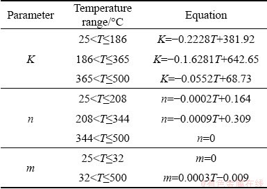
where σ is the stress (MPa), K is a material constant related to the strength of the materials (MPa), εp is the total plastic strain,  is the equivalent plastic strain rate (s-1), m is the strain rate sensitivity coefficient, and n is the strain hardening coefficient. K, m and n are temperature-related parameters and the values are taken from previous publications by ALANKAR and WELLS [26], as given in Table 2. The two coefficients
  and
and  are initial strain and initial strain rate, respectively, and are set to be 1×10⁻⁶ and 1×10⁻⁴ s-1, respectively, in order to achieve the fast convergence.
Table 1 Chemical composition (wt.%) of AA6111 alloy used in this study [26]

2.1.2 Constitutive equations above solidus temperature
Table 2 Key parameters of AA6111 alloys below solidus temperature [26]
The constitutive equation above solidus temperature of AA6111 alloy is [27]
 (2)
(2)
where fs is the solid fraction, fp is the pore fraction, Kp is the ratio coefficients of porosity. The value fp is set to be 0 and Kp is always 1.0 in this model. σs is the solid flow stress (MPa) of the elastic- perfectly-plastic type, as shown below:
 (3)
(3)
where  is the strain rate (s-1) and T is the temperature (°C).
nss is a strain hardening parameter related to the grain size of the solid skeleton. The solidification path of AA6111 was calculated by a thermodynamic software Jmatpro, as shown in Fig. 1. The stress-strain curves of AA6111 alloy in the semi-solid state were obtained using a three- phase simulation method [27], as shown in Fig. 2. The phenomenological expression of nss in Eq. (4) was derived by regression analysis based on the true stress-strain curve:
nss=-6.43833×10⁻⁴h2+0.03502h+0.0078 (4)
where
 (5)
(5)
 (6)
(6)
 (7)
(7)
 (8)
(8)
where  is the average grain size, h is the thickness of the liquid channels between grains, a and b are fitting parameters taken from Ref. [10], Q is the growth restriction factor and has a value of 13.54 [10] and
  is the cooling rate [27]. Since Eq. (4) is a quadratic equation, it has a peak point at h=27.19 μm. Above this value, nss is fixed to be zero. Note that Eq. (4) is only valid above the solidus temperature. From 500 °C to the solidus temperature, it is assumed that the constitutive behavior is a linear interpolation between the values obtained by Eq. (1) at 500 °C and Eq. (2) at 510 °C.

Fig. 1 Solidification path of AA6111 alloy based on Scheil simulation

Fig. 2 True stress-strain curves of AA6111 alloy at different solid fractions [27]
2.2 Thermal and physical properties
The thermal and physical properties of AA6111 alloy used in this model were calculated using thermodynamic software Jmatpro, as given in Table 3.
2.3 Finite element model
Table 3 Material properties used in DC casting process
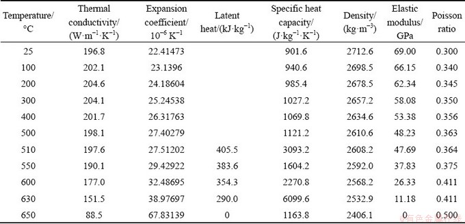

Fig. 3 Schematic diagram of two-dimensional axi- symmetric coupled thermomechanical model, showing locations of boundary conditions applied (Γ1-Γ4)
Figure 3 shows the schematic diagram and the boundary conditions in the model. The coordinate method used in this simulation is the Lagrange method. The simulation method, boundary conditions Γ2 and Γ3 and constitutive relations are described in detail in Ref. [10]. The casting temperature is 665 °C. The casting conditions are listed in Table 4. The constitutive equation of AA6111 was written in the subroutine UHARD of commercial software ABAQUS. The mesh module was used to divide the grids and each grid was 5 mm wide and 4 mm high. The dead-live unit method was used in this simulation. In order to simulate the DC casting process, the billet was kept at a fixed position, and the continuous feeding of liquid metal was achieved by gradually activating the horizontal unit layer. The activation speed of the unit layer and the water-cooling boundary moved upward at a speed equal to the casting speed, as shown in Fig. 3. Then, the DC casting simulation ofAA6111 was realized by the two-dimensional axisymmetric coupled thermomechanical model implemented through ABAQUS.
Table 4 Initial and transient boundary conditions of process parameters

The result of the temperature distribution of the billet is shown in Fig. 4. The result shows that the temperature of the surface of the casting rapidly drops due to the impact of the primary and secondary cooling water. In the center of the billet, the metal liquid has the highest temperature and is finally solidified, resulting in a valley distribution of the temperature field.
2.3.1 Boundary conditions at Γ2
The relationship to describe the heat transfer coefficient (HTC) during secondary cooling was based on the results from DREZET et al [28]. In order to study the effects of secondary cooling on the fraction of pores, the boiling curve was recorded. The base boiling curve, H(1), was multiplied by scale factors of 1.25, 1.5 and 2.0 for simulating the influence of water flow rates similar to previous reports by HAO et al [29], as graphically shown in Fig. 5.
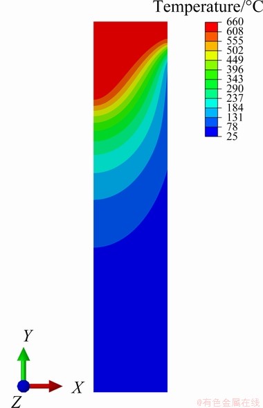
Fig. 4 Contour map showing temperature of nodes at end of DC casting process

Fig. 5 HTC curves in secondary cooling zone as function of computed surface temperature
2.3.2 Boundary conditions at Γ4
The HTC of the bottom cooling varied from 300 to 2000 W/(m2・K) due to the influence of water impingements and air gap during actual casting according to the study of SENGUPTA et al [30]. Therefore, the HTC of boundary condition Γ4 was set to be 800, 1200, 1600 and 2000 W/(m2・K), in order to study the effects of the HTC at the bottom on HTS.
2.4 Pore fraction hot tearing criterion
The hot tearing criterion [20] is based on the critical pressure drop △Pcr, which is described as

 (9)
(9)
where β is solidification shrinkage; △Tf(=TL-TS) is the freezing range, in which TL is the liquidus temperature and TS is the solidus temperature; μ is the viscosity; G is temperature gradient;  and
and  are strain rates parallel with and perpendicular to the thermal gradient, respectively; λ2 is secondary dendrite arm spacing; Ide,
  and Ish are associated with the terms relevant to the deformation, the deformation-induced shrinkage, and the shrinkage, respectively. It is assumed that once the pressure drop exceeds the critical pressure drop △Pcr, the fluid flow stops. Therefore, further shrinkage and deformation beyond the critical liquid fraction fl,cr will result in the formation of porosity.
When flow stops at fl,cr, mass conservation can be used to determine the porosity that must form to feed the remaining shrinkage [15]:
 (10)
(10)
A similar set of variables can be used to calculate deformation-related porosity: fp,de,x and fp,de,y,
 (11)
(11)
 (12)
(12)
where fl is the liquid fraction, and θ(=(T-Tsol)/△Tf) is a dimensionless temperature introduced in this tearing criterion and Tsol represents the solidus temperature.
Finally, there is additional strain rate-induced shrinkage porosity,
 (13)
(13)
where Vsx is the deformation velocity parallel to the thermal gradient, and  is the isotherm velocity.
As shown in Eqs. (10)-(13), the total porosity during the late stage of solidification below fl,cr consists of four components: fp,sh, fp,de,x, fp,de,y and  . Further, the total deformation pore fraction and total pore fraction are expressed as fp,de and fp,sum:
fp,de=fp,de,x+fp,de,y (14)
fp,sum=fp,sh++fp,de,x+fp,de,y (15)
2.5 Coupling of FE simulation with hot tearing criterion
The temperature, cooling rate, temperature gradient, and stress etc of FE nodes were extracted by a python scripts at the temperature where fs equals 0.98. Then, these data were calculated by a C# program to obtain the pore fraction distribution of the billet. The HTS of AA6111 alloy during DC casting was predicted by the pore fraction hot tearing model.
3 Results and discussion
3.1 Effects of casting speed on HTS
The effects of casting speed on the HTS (Case B) are investigated, as shown in Fig. 6. Figures 6(a, b) show the distributions of fp,sum and fp,de along the centerline of the billet, respectively. It can be seen that the maximum values of fp,sum and fp,de appear at the start-up phase and increase with increasing casting speed. The location of the maximum pore fraction in the start-up phase moves downwards along the centerline as the casting speed increases, which is 36, 28, 24 and 20 mm, respectively. The pore fraction distributions along the radius of the billet at different casting speeds are shown in Figs. 6(c, d). It can be seen that there are high fp,sum and fp,de near the centerline of the billet and they decrease gradually along the radius. This indicates that high casting speed results in a high tendency to hot tearing and the center of the billet has the highest HTS. This is consistent with DC casting practice that hot tearing is more easily formed with a higher casting speed and develops in the center of a billet [31,32].
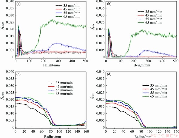
Fig. 6 Distribution of fp,sum (a, c) and fp,de (b, d) along centerline (a, b) and radius (c, d) of billet during DC casting at different casting speeds
The casting conditions of Case A are selected to analyze the HTS variations. Figures 7(a, b) show the contour maps of pore fraction in the entire billet. The results indicate that the region near the centerline in the start-up phase has higher pore fractions than other locations in the billet. Figures 7(c, d) show that the changes of fp,sum and fp,de are related to the change of the strain rate and . In the start-up phase, fp,sum, fp,de and fp,sh increase rapidly and reach a peak at 24 mm. In the height range of 56-152 mm, fp,de is zero since and are both zero according to Eqs. (11), (12) and (14). In the steady phase, fp,sum is not zero because of the contribution of fp,sh. This means that if the shrinkage porosity caused by solidification shrinkage exceeds a critical value, hot tearing will occur, which is affected by the alloy composition such as eutectic content and shape in the late stage of solidification [33,34].
3.2 Effects of heat transfer at bottom on HTS
CARON et al [35] show that the HTC values are different for different casting surfaces by studying the HTC of the metal-mold interface at the bottom of Al alloy castings. It is believed that there are at least two ways to change the HTC at the bottom: one is using different materials of the bottom, and the other is changing the contact area between the billet and the bottom interface. In any case, the root cause is attributed to the changes in HTC. In Case C, the effect of HTC at the bottom on the HTS of DC casting is considered, and the results are shown in Fig. 8. It can be seen that the maximum values of fp,sum and fp,de decrease with the HTS increasing. The location of the maximum point of the pore fraction moves up along the centerline as the HTC increases, which is 16, 28, 40 and 48 mm, respectively. As the HTC at the bottom increases, fp,de in the steady phase gradually decreases to close to 0. When the HTC is 800 W/(m2・K), fp,sum and fp,de rise first when the distance from the bottom exceeds 100 mm, reach a peak of 0.015 at the height of 250 mm, and then decrease to 0 at a height of 500 mm. When the HTC changes from 800 to 2000 W/(m2・K), the maximum pore fraction in the start-up phase decreases by more than 50%, but the height increases by 2 times. Although the increase of the heat transfer at the bottom can reduce the HTS of the billet, it will cause the position of the maximum pore fractions to rise in the start-up phase. Therefore, it is very important to identify the HTC at the bottom where hot tearing cannot be generated, as hot tearing will reduce cutting length at the bottom of the billet.

Fig. 7 Contour maps showing variation of fp,sum (a) and fp,de (b), and distribution of fp,sum, fp,de and fp,sh (c) and strain rate (d) along centerline as function of height at casting speed of 55 mm/min

Fig. 8 Distribution of fp,sum (a) and fp,de (b) along centerline of billet during DC casting at different HTC values of bottom (Casting speed of 55 mm/min)
3.3 Effects of secondary cooling water on HTS
The effects of secondary cooling water rates (SWFR) on the HTS (Case D) are shown in Fig. 9. It can be seen that as the HTC increases, the values of fp,sum and fp,de in the start-up phase decrease slightly, and the position of the maximum value move towards the bottom, which is 24, 20 and 16 mm, respectively. When the HTC curve is 1.50H(1), fp,de along the centerline in steady phase is reduced to be zero, and the pore fraction of 1.25H(1) is between the pore fractions of H(1) and 1.50H(1). This indicates that the increase of SWFR can reduce the pore fractions in the steady phase. Similar results were experimentally found by ESKIN et al [36].
When the casting speed is increased from 55 to 65 mm/min, the effects of SWFR on HTS are obtained, as shown in Figs. 9(c, d). As SWFR increases, the maximum point of fp,sum and fp,de in the start-up phase gradually decreases and moves toward the bottom. Beyond a height of 100 mm, both the fp,sum and fp,de rise and reach a platform at a height of around 200 mm. It can be concluded that when the casting speed is 65 mm/min, although HTC caused by SWFR is increased, fp,sum and fp,de in the steady phase of the billet cannot be eliminated completely. ESKIN et al [36] performed DC casting experiment of Al-4.5wt.%Cu and the results show that amount and size of pores tend to increase towards the center of a billet as the SWFR increases. This illustrates that this model can used to predict the changes of pore defects with the changes of SWFR during DC casting process.
3.4 Effects of billet radius on HTS
Large-sized billets of high-strength Al alloys during DC casting usually have a high tendency to hot cracking [37]. The selection of casting radius is very important for avoiding the HTS of a billet. The effects of the billet radius (120-180 mm) on the HTS are investigated. Casting speed is set to be 65 mm/min because there is no deformation pore in the steady phase at casting speeds below 55 mm/min when the radius is 140 or 120 mm. The results show that the maximum pore fraction and its location in the start-up phase decrease slightly as the radius decreases, as shown in Fig. 10. Beyond 132 mm from the bottom, fp,sum and fp,de increase drastically and reach a plateau. When the radius is reduced to 120 mm, fp,de in the central region of the billet is almost close to zero. Increasing the radius will increase the heat transfer distance from the centerline to the surface. The change in the pore fraction in the start-up phase further suggests that increasing the radius will also affect the heat transfer at the bottom. The increase in radius means smaller surface heat dissipation, which is similar to the effect of SWFR in principle. However, the position of the maximum pore fraction hardly changes when the radius is in the range of 140-180 mm. This is different from the results in Section 3.3 that the lager the SWFR is, the lower the location of maximum pore fractions is. It is considered that the cooling conditions with different casting radii are complicated. And this result is consistent with the industrial practice that the larger the radius of the billet is, the harder it is to cast [38].
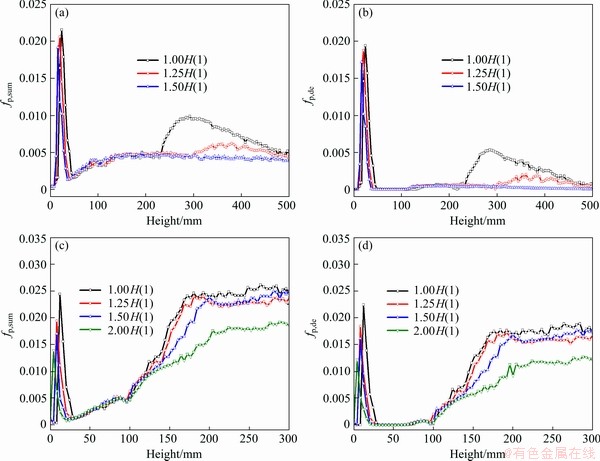
Fig. 9 Distribution of fp,sum (a, c) and fp,de (b, d) at casting speed of 55 (a, b) and 65 mm/min (c, d) along centerline of billet during DC casting with different SWFR
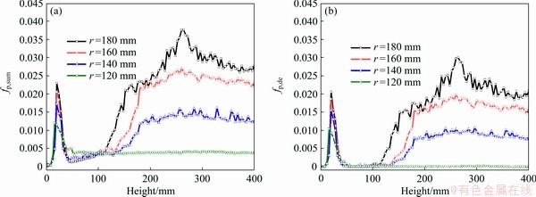
Fig. 10 Distribution of fp,sum (a) and fp,de (b) along centerline of billet during DC casting with different radii at casting speed of 65 mm/min
4 Conclusions
(1) The FE simulation of AA6111 alloy during DC casting process was implemented by coupling UHARD subroutines. The temperature distribution of the billet during DC casting was obtained and extracted for HTS modeling.
(2) Using predicted temperature, temperature gradient, cooling rate, and stress in the billet over time, a pore fraction distribution model was developed to calculate the pore fraction in the entire billet. Combining the pore fraction model and the hot tearing criterion, a pore fraction HTS model was developed to simulate the highest HTS in the center of the billet during the start-up phase of DC casting process.
(3) The influence of casting conditions on HTS was systematically studied. The results show that the HTS of the billet increases as the casting speed and the radius of the billet increase. It reduces as the HTC at the bottom or secondary cooling water flow rate grows.
(4) This model can also predict the location of the maximum pore fraction during DC casting. The location of the maximum pore fraction moves towards the bottom of the billet with the increase of casting speed and SWFR, while it moves towards the center of the billet with increasing heat transfer coefficient at the bottom or expanding the casting radius.
(5) The optimized casting practice shows that for a casting radius of 160 mm, the casting speed should be 55 mm/min, the secondary water cooling curve should be 1.50H(1), and the HTC at the bottom should be 1600 W/(m2・K) in order to avoid hot tearing.
Acknowledgments
The authors would like to extend their sincere gratitude to all members of the Integrated Computational Materials Engineering (ICME) Lab at Beijing Institute of Technology (BIT).
References
[1] LUO H J, JIE W Q, GAO Z M, ZHENG Y J. Numerical simulation for macrosegregation in direct-chill casting of 2024 aluminum alloy with an extended continuum mixture model [J]. Transactions of Nonferrous Metals Society of China, 2018, 28(5): 1007-1015.
[2] WANG X F, SHI T Y, WANG H B, ZHOU S Z, PENG W F, WANG Y G. Effects of strain rate on mechanical properties, microstructure and texture of Al-Mg-Si-Cu alloy under tensile loading [J]. Transactions of Nonferrous Metals Society of China, 2020, 30(1): 27-40.
[3] ACOSTA G, VELEVA L, LOPEZ J L, LOPEZ-SAURI D A. Contrasting initial events of localized corrosion on surfaces of 2219-T42 and 6061-T6 aluminum alloys exposed in Caribbean seawater [J]. Transactions of Nonferrous Metals Society of China, 2019, 29(1): 34-42.
[4] LIU C L, AZIZI-ALIZAMINI H, PARSON N C, POOLE W J, DU Q. Microstructure evolution during homogenization of Al-Mg-Si-Mn-Fe alloys: Modelling and experimental results [J]. Transactions of Nonferrous Metals Society of China, 2017, 27(4): 747-753.
[5] LUO H J, JIE W Q, GAO Z M, ZHENG Y J. Numerical simulation for macrosegregation in direct-chill casting of 2024 aluminum alloy with an extended continuum mixture model [J]. Transactions of Nonferrous Metals Society of China, 2018, 28(5): 1007-1015.
[6] DAVIDSON C, VIANO D, LU L, STJOHNET D. Observation of crack initiation during hot tearing [J]. International Journal of Cast Metals Research, 2006, 19(1): 59-65.
[7] PHILLION A B, COCKCROFT S L, LEE P D. A new methodology for measurement of semi-solid constitutive behavior and its application to examination of as-cast porosity and hot tearing in aluminum alloys [J]. Materials Science and Engineering A, 2008, 491: 237-247.
[8] PHILLION A B, COCKCROFT S L, LEE P D. X-ray micro-tomographic observations of hot tear damage in an Al-Mg commercial alloy [J]. Scripta Materialia, 2006, 55(5): 489-492.
[9] FARUP I, DREZET J M, RAPPAZ M. In situ observation of hot tearing formation in succinonitrile-acetone [J]. Acta Materialia, 2001, 49(7): 1261-1269.
[10] JAMALY N, PHILLION A B, DREZET J M. Stress-strain predictions of semisolid Al-Mg-Mn alloys during direct chill casting: Effects of microstructure and process variables [J]. Metallurgical and Materials Transactions B, 2013, 44(5): 1287-1295.
[11] BAI Q L, LIU J C, LI H X, DU Q, KATGERMAN L, ZHANG J S, ZHUANG L Z. A modified hot tearing criterion for direct chill casting of aluminium alloys [J]. Materials Science and Technology, 2016, 32(8): 846-854.
[12] ESKIN D G, KATGERMAN L. Mechanical properties in the semi-solid state and hot tearing of aluminium alloys [J]. Progress in Materials Science, 2004, 49(5): 629-711.
[13] ESKIN D G, KATGERMAN L. A quest for a new hot tearing criterion [J]. Metallurgical and Materials Transactions A, 2007, 38(7): 1511-1519.
[14] RAPPAZ M, DREZET J M, GREMAUD M. A new hot-tearing criterion [J]. Metallurgical and Materials Transactions A, 1999, 30(2): 449-455.
[15] MONROE C, BECKERMANN C. Prediction of hot tearing using a dimensionless Niyama criterion [J]. JOM, 2014, 66(8): 1439-1445.
[16] SUYITNO D G, ESKIN L K. Structure observations related to hot tearing of Al-Cu billets produced by direct-chill casting [J]. Materials Science and Engineering A, 2006, 420: 1-7.
[17] M’HAMDI M, Mo A. On modelling the interplay between microporosity formation and hot tearing in aluminium direct-chill casting [J]. Materials Science and Engineering A, 2005, 413: 105-108.
[18] HAN J Q, WANG J S, ZHANG M S, NIU K M. Susceptibility of lithium containing aluminum alloys to cracking during solidification [J]. Materialia, 2019, 5: 100203.
[19] CARLSON K D, BECKERMANN C. Prediction of shrinkage pore volume fraction using a dimensionless Niyama criterion [J]. Metallurgical and Materials Transactions A, 2009, 40(1): 163-175.
[20] DOU R, PHILLION A B. Application of a pore fraction hot tearing model to directionally solidified and direct chill cast aluminum alloys [J]. Metallurgical and Materials Transactions A, 2016, 47(8): 4217-4225.
[21] SAVRAN V I, KATGERMAN L, ESKIN D G. Effects of alloy composition and casting speed on structure formation and hot tearing during direct-chill casting of Al-Cu alloys [J]. Metallurgical and Materials Transactions A, 2004, 35(11): 3551-3561.
[22] LUDWIG O, DREZET J M, MARTIN C L, SUERY M. Rheological behavior of Al-Cu alloys during solidification constitutive modeling, experimental identification, and numerical study [J]. Metallurgical and Materials Transactions A, 2005, 36(6): 1525-1535.
[23] COLLEY L J, WELLS M A, MAIJER D M. Tensile properties of as-cast aluminum alloy AA5182 close to the solidus temperature [J]. Materials Science and Engineering A, 2004, 386: 140-148.
[24] BAI Q L, LI H X, DU Q, ZHANG J S, ZHUANG L Z. Mechanical properties and constitutive behaviors of as-cast 7050 aluminum alloy from room temperature to above the solidus temperature [J]. International Journal of Minerals, Metallurgy, and Materials, 2016, 23(8): 949-958.
[25] PHILLION A B, COCKCROFT S L, LEE P D. A three-phase simulation of the effect of microstructural features on semi-solid tensile deformation [J]. Acta Materialia, 2008, 56(16): 4328-4338.
[26] ALANKAR A, WELLS M A. Constitutive behavior of as-cast aluminum alloys AA3104, AA5182 and AA6111 at below solidus temperatures [J]. Materials Science and Engineering A, 2010, 527: 7812-7820.
[27] PHILLION A B, COCKCROFT S L, LEE P D. Predicting the constitutive behavior of semi-solids via a direct finite element simulation: Application to AA5182 [J]. Modelling and Simulation in Materials Science and Engineering, 2009, 17(5): 055011.
[28] DREZET J M, RAPPAZ M, GRüN G U, GREMAUD M. Determination of thermophysical properties and boundary conditions of direct chill-cast aluminum alloys using inverse methods [J]. Metallurgical and Materials Transactions A, 2000, 31(6): 1627-1634.
[29] HAO H, MAIJER D M, WELLS M A, COCKCROFT S L, SEDIAKO D, HIBBINS S. Development and validation of a thermal model of the direct chill casting of AZ31 magnesium billets [J]. Metallurgical and Materials Transactions A, 2004, 35(12): 3843-3854.
[30] SENGUPTA J, COCKCROFT S L, MAIJER D, WELLS, M A, LAROUCHE A. The effect of water ejection and water incursion on the evolution of thermal field during the start-up phase of the direct chill casting process [J]. Journal of Light Metals, 2002, 2(3): 137-148.
[31] FARUP I, MO A. Two-phase modeling of mushy zone parameters associated with hot tearing [J]. Metallurgical and Materials Transactions A, 2000, 31(5): 1461-1472.
[32] NOVIKOV II, GRUSHKO O E. Hot cracking susceptibility of Al-Cu-Li and Al-Cu-Li-Mn alloys [J]. Materials Science and Technology, 1995, 11(9): 926-932.
[33] VINODH G, NODOOSHAN H R J, LI D, ZENG X Q, HU B, CARTER J T, SACHDEV A K. Effect of Al content on hot-tearing susceptibility of Mg-10Zn-xAl alloys [J]. Metallurgical and Materials Transactions A, 2020, 51(4): 1897-1910.
[34] POURGHARIBSHAHI M, DIVANDARI M, SAGHAFIAN H, TIMELLI G. Eutectic nucleation in 7xxx series aluminum alloys from a non-classical viewpoint [J]. Metallurgical and Materials Transactions A, 2020, 51(9): 4572-4583.
[35] CARON E J F R, BASERINIA A R, NG H, WELLS M A, WECKMAN D C. Heat-transfer measurements in the primary cooling phase of the direct-chill casting process [J]. Metallurgical and Materials Transactions B, 2012, 43(5): 1202-1213.
[36] ESKIN D G, ZUIDEMA J Jr, SAVRAN V I, KATGERMAN L. Structure formation and macrosegregation under different process conditions during DC casting [J]. Materials Science and Engineering A, 2004, 384: 232-244.
[37] LUO Y J, ZHANG Z F, LI B, GAO M W, QIU Y, HE M. Effects of annular electromagnetic stirring coupled with intercooling on grain refinement and homogeneity during direct chill casting of large-sized 7005 alloy billet [J]. JOM, 2017, 69(12): 2640-2643.
[38] ELLINGSEN K, DU Q, M’HAMDI M, GIHLEENGEN B E, LEDAL R, TVEITO K O, HAKONSEN A. Experimental study and numerical analysis of cracking during DC casting of large dimension 7075 aluminium billets [C]//TMS Annual Meeting & Exhibition. Springer, 2018: 895-900.
陈东旭1,豆瑞峰2,韩加强2,王俊升1,3
1. 北京理工大学 材料学院,北京 100081;
2. 北京科技大学 材料科学与工程学院,北京 100083;
3. 北京理工大学 前沿科学交叉科学研究院,北京 100081
摘 要:为了预测凝固过程中的热裂敏感性(HTS)并提高铝合金铸件的质量,采用直接有限元(FE)方法建立AA6111的本构方程。通过有限元模型和热撕裂准则的耦合,建立用于工业AA6111合金半连续铸造的热撕裂模型。将此模型应用于实际制造过程,表征铸造速度、底部冷却、二次冷却以及几何形状变化对HTS的影响。结果表明,铸坯的HTS随着速度和铸坯半径的增大而增加,而随着底部界面传热系数或二次水冷却速率的增大而降低。该模型展示出在模拟热裂引发时结合最大孔隙率的能力,这将对优化铸造条件和化学成分以达到HTS最小化从而控制铸造质量产生重大影响。
关键词:汽车轻量化;AA6111合金;半连续铸造;热裂判据;孔隙分数;有限元模拟
(Edited by Bing YANG)
Corresponding author: Jun-sheng WANG; Tel: +86-10-68915043; E-mail: junsheng.wang@bit.edu.cn
DOI: 10.1016/S1003-6326(20)65451-6

