
Formation of integral fins function-surface by extrusion-ploughing process
CHEN Ping(�� ƽ), TANG Yong(�� ��), LIU Xiao-kang(��С��), LIU Xiao-qing(������)
College of Mechanical Engineering, South China University of Technology, Guangzhou 510640, China
Received 9 November 2005; accepted 10 May 2006
Abstract: An extrusion-ploughing process was presented to fabricate the integral fin function-surface. Cutting edge inclination angle and rake angle can be calculated from the tool��s geometry relationship. The description of fins�� geometry characters was standardized. The experiments show that, when the middle cutting edge��s inclination angle �� is less than 35?, continuous fin will come out; when �� is between 35? and 55?, the fins will be saw-tooth ones, and the fins will be torn when this angle is above 55?; when the extrusion angle �� is between 60? and 150?, the fins will appear, or else, the fins will be torn into chips from the base. Forming angle and clearance angle have little effect on fin��s formation. For continuous fin, its height is close to cutting depth when it is small, but it will become approximately constant as cutting depth grows; for saw-tooth fins, the width, the height, as well as the clearance will increase with the increase of cutting depth, but the increment of clearance is small; neither for continuous fin, nor for saw-tooth ones, cutting velocity has little influence on their structure parameters.
Key words: fins; integral fins; extrusion-ploughing formation; heat function surface
1 Introduction
The ever-increasing integrity of electronic chips results in high heat flow density, which makes the cooling become the ever more serious[1-5]. The traditional single-scale and simple figure surface heat-function macro-structure can not meet the cooling requirement, which slows the development of high-integrity chips.
At present, the research of surface heat function structure(SHFS) mainly focuses on the analysis and design of heat transmission in macro-scale. For example, Geogria Institute of Technology[6] has done some researches on the surface macro-structure and meta-structure. With the worsening of cooling, the study of SHFS is turning to meta/micro field, such as the development of micro heat transfer[7-12]. The machining of meta-structure and micro-structure of the macro structure surface[13-15], as well as the key technology, has been studied at home.
Solving the present high heat flow density needs to design heat function surface macro structure, based on the special radiating environment requirement and
external convection pattern, even needs to employ surface meta-structure and micro-structure to strengthen the heat transmission. But which SHFS to use and how to machine remain unclear; the description, design, machining and the application of SHFS lack necessary theories, so it can��t realize the design and machining of SHFS effectively, according to the active requirement, yet nor can realize the digital design and fabrication.
In this work, an extrusion-ploughing technology with no chip is presented to generate fin SHFS��and the machining theory of SHFS can be richened and perfected by studying the forming mechanism and relevant influencing factors, which provides the optimum method for high heat flow density.
2 Experimental
2.1 Experiment
The experiment was carried out on the universal planer B6050B. The tool was made of high speed steel W18Cr4V, and the workpiece was made of red copper T2. The fitness of the workpiece and the tool is shown in F
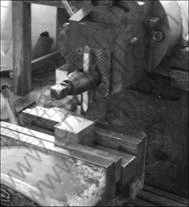
Fig.1 Experimental device of extrusion-ploughing process
2.2 Formed tool
Contrary to the common cutting process which cuts out the redundant metal to get the part, the extrusion- ploughing process makes the chips remain on the base, thus the radiating area is enlarged; not only the material��s utilization is bettered, but also the problem of practical contact thermal resistance in heat control is solved. The design of formed tool should fully reflect the non-chip techniques. As shown in Fig.2, the tool��s moving direction is parallel to the formed plane.
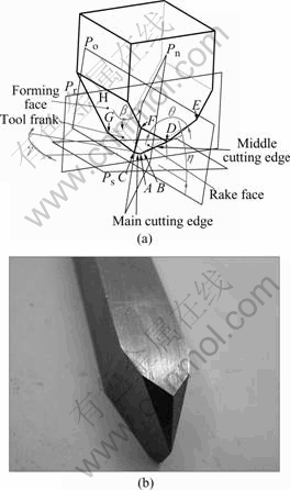
Fig.2 Extrusion-ploughing formed tool: (a) Tool��s geometry parameters; (b) Tool
2.3 Tool��s angles
From Fig.2, differing from the common planer tool, the extrusion-ploughing formed tool has 3 characters. The first is that the rake angle �� is minus, and the second is that the cutting edge inclination angle �� is not zero, and the last is that the tool has multi cutting edges, so the cutting pattern corresponds to the multi-edge cutting with inclination angle. Supposing the cutting velocity is along Z minus axis, that is perpendicular to the base level Pr and pointing to the tool. From tool��s geometry relationship, �� and �� can be calculated as follows:
 (1)
(1)


 (2)
(2)
where
A= (3)
(3)
B= (4)
(4)
 (5)
(5)
3 Extrusion-ploughing forming process
3.1 Critical depth in double edge cutting
In Fig.2, when ap equals Y value of intersection of line FC and plane Pr, both main cutting edge and side cutting edge cut the workpiece simultaneously, the cutting depth is named as the critical depth hcr.
From Fig.3, the critical depth can be solved as
 (6)
(6)
where
 (7)
(7)
 (8)
(8)
 (9)
(9)
 (10)
(10)
 (11)
(11)
 (12)
(12)

Fig.3 Standard view: (a) Front view; (b) Left view
3.2 Extrusion-ploughing process
In the beginning of extrusion-ploughing process, before the main and the side cutting edges contact the workpiece, the wedge block that consists of middle cutting edge and the two rake faces directly cuts the workpeice, and the extrusion plastic deformation appears.
The cutting sequence between the main cutting edge and the side cutting edge relies on hcr. When ap��hcr, the main cutting edge cuts at first, and the side cutting edge goes first on the contrary conditions.
As the tool goes forward, either the main or the side cutting edge cuts the metal. This process is similar to the multi-edge cutting with large cutting edge inclination angle and oblique angle, and there is angle �� between the flow chip direction and the cutting edge��s normal. Since the formed tool is symmetric, so some interference appears in the edge of the two chips; the breakage of the adjacent metals can eliminate this interference. The existence of middle edge and the sharp edge create the big shearing stress in the chips�� edge, so the shear concentration is easy to come out, thus the chips break. The rake angle is minus, and the chip clings to the rake face. The stress resulted from the rake face��s extrusion makes the metal in the front of the chip go upwards, the geometry and the height of the raised metal decide the fin��s figure and height; the fin will be higher and narrower when it is near the fake face. The extrusion height gradually goes higher from the middle edge to the side edge.
All the chips are extruded to one side of the formed face when they pass along the side cutting edge, and they join the base to form the fins whose height and width vary with the change of tool��s displacement.
Eventually continuous fins or saw-tooth fins are formed as seen as Fig.4, and some micro dentate configurations could be produced on continuous fins�� tip (Fig.5). The workpiece can form integral SHFS which includes ploughed channels and fins.
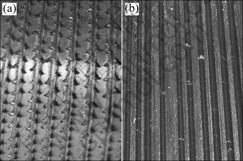
Fig.4 Fin structure: (a) Saw-tooth fins; (b) Continuous fins
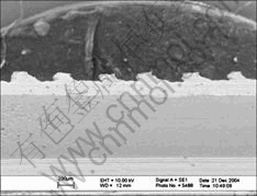
Fig.5 Meta-structure/micro-structure
4 Results and discussion
4.1 Description of fin��s structure
As shown in Fig.6, for the continuous fins, the parameters for description are the macro fin��s height hl and extrusion width Ble; but for the saw-tooth fins, the parameters are width dj, height hj and saw-tooth clearance dl.
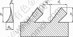
Fig.6 Parameters description of fin��s structure features
For the continuous fins, the fin��s height varies with
the change of tool��s displacement. Supposing the macro fin��s height is the mean value of fins at different points, then, we can get
 (13)
(13)
where n is the number of the selected points, and hli is the corresponding height of fin.
For the saw-tooth fins,
 (14)
(14)
 (15)
(15)
 (16)
(16)
where n is the fins�� total number; dji, hji and dli represent the width, height and saw-tooth clearance, respectively.
4.2 Influence of tool��s geometry parameters on fin��s formation
Either the continuous fins or the saw-tooth fins are created in the extrusion-ploughing process, the consequence is dominated by tool��s geometry para- meters.
4.2.1 Inclination angle �� of middle cutting edge
Changing �� while supposing other conditions remain the same, we can get fins with different structures. The experiments show that, when �� is less than 35?, the continuous fins are easy to come out, and with the increase of ��, the macro saw-tooth fin structure can be generated either with different cutting velocities or with different cutting depths; when �� reaches 55?, the saw- tooth fins are inclined to be torn into small chips. So, we can conclude that, �� is one of the main factors that decide fin��s pattern.
4.2.2 Extrusion angle ��
Since the cutting edge inclination angle is not null, the cutting velocity is not vertical to tool��s cutting edge, and the cutting velocity has component along the cutting edge��s direction. From Eqn.(1), we can see that, the cutting edge inclination angle decreases with the increase of �� if other angles are fixed; that is to say, the decrease of velocity��s component weakens the metal��s flow along the cutting edge��s direction, the shearing slip direction of the cutting layer changes and chip��s flowing angle diminishes. The fins can be generated when �� is between 60? and 150?, and when �� is beyond this range, the fin can be easily torn into small chips.
4.2.3 Formed angle ��
The angle �� has little influence on fin��s structure; it generally controls the figure of ploughed channels.
4.2.4 Clearance angle ��
The angle �� also has little influence on fin��s structure; it is mainly used to reduce frictional resistance in the extrusion-ploughing process.
4.3 Influence of processing parameters on fin��s for- mation
4.3.1 Influence of processing parameters on formation of continuous fins
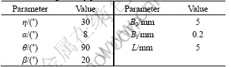
The tool��s parameters selected to machine the continuous fins are listed in Table 1.
Table 1 Tool��s geometry parameters for continuous fins
1) Influence of cutting depth
As shown in Fig.7, the fin��s height is close to the cutting depth when the cutting depth is small; the height doesn��t increase very much as the cutting depth increases, it stays at a certain value.
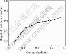
Fig.7 Relationship between cutting depth and fin��s height (V��177 mm/s)
2) Influence of cutting velocity
As shown in Fig.8, the fin��s height fluctuates very little with the change of cutting velocity, so the cutting velocity affects the fin��s height very little.
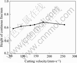
Fig.8 Relationship between cutting velocity and fin��s height (ap=1.44 mm)
4.3.2 Influence of processing parameters on formation of saw-tooth fins
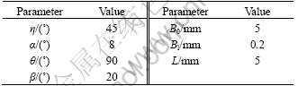
The tool��s parameters selected to machine the saw-tooth fins are listed in Table 2.
Table 2 Tool��s geometry parameters for saw-tooth fins
1) Influence of cutting depth
As shown in Fig.9, the width, the height and the saw-tooth clearance of saw-tooth fin augment as cutting depth increases. The increment of the width is obvious, but the increment of the saw-tooth clearance is not. So, the fin��s saw-tooth clearance tends to be stable as cutting depth increases; the number in unit length lessens slowly, and the saw-tooth fin grows bigger.
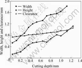
Fig.9 Relationship between cutting depth and parameters of saw-tooth fin (V=177 mm/s)
2) Influence of cutting velocity
As seen in Fig.10, with the increase of cutting velocity, the width, the height and the saw-tooth clearance of saw-tooth fin change very little, their values tend to be stable. So, the cutting velocity has little effect on the structure parameters of saw-tooth fins.
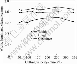
Fig.10 Relationship between cutting velocity and parameters of saw-tooth fin (ap=0.6 mm)
5 Conclusions
The extrusion-ploughing process is a cutting process with no chip, and its theory involves metallic cutting and plastic extrusion. Different from the ordinary cutting process which cuts out the redundant metal to get the part, this process makes the chips remain on the base, and thus different SHFS can be got.
1) Based on the formed tool��s geometry relation, the calculation expressions of cutting edge inclination angle and rake angle are gained, the descriptions of fin��s structure characteristic parameters (such as hl, bl, dj, hj, dl) are put forward. The formation of integral fin structure SHFS by extrusion-ploughing process is analyzed.
2) When the middle edge��s inclination angle �� is less than 35?, the continuous fins will come out; when �� is between 35? and 55?, the fins will be saw-tooth ones, and the fins will be torn when this angle is above 55?. When the extrusion angle �� is between 60? and 150?, the fins will appear, or else, the fins will be torn into chips from the base. The forming angle and clearance angle have little effect on fin��s formation.
3) For the continuous fin, its height is close to cutting depth when it is small, but it will become approximately constant as cutting depth grows; for the saw-tooth fins, the width and the height, as well as the saw-tooth clearance will increase with the increase of cutting depth, but the increment of the saw-tooth clearance is small. Neither for the continuous fins, nor for the saw-tooth ones, cutting velocity has little influence on their structure parameters.
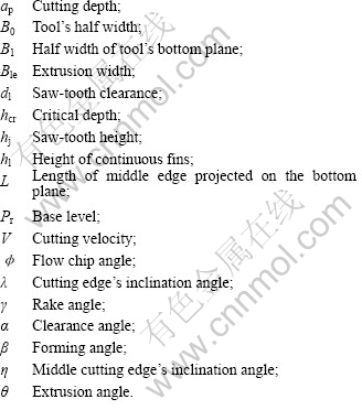
Nomenclature
References
[1] YAZAWA K, BAR-COHEN A. Energy efficient cooling of notebook computers [A]. 2002 Inter Society Conference on Thermal Phenomena [C]. San Diego, CA: Institute of Electrical and Electronics Engineering Inc, 2002: 785-791.
[2] ZHANG H Y, PINJALA D, NAVAS O K, CHAN P K, LIU X P, HAYASHI H, HAN J B. Development of thermal solutions for high performance laptop computers [A]. 2002 Inter Society Conference on Thermal Phenomena [C]. San Diego, CA: Institute of Electrical and Electronics Engineering Inc, 2002: 433-440.
[3] IM Y, CHO H, KIM M, PAEK J. Micro cooling application on high density memory module [A]. 19th IEEE SEMI-THERM Symposium [C]. San Jose, CA: Institute of Electrical and Electronics Engineering Inc, 2003: 179-184.
[4] AVENAS Y, GILLOT C, BRICARD A, SCHEAFFER C. On the use of flat heat pipes as thermal spreaders in power electronics cooling [A]. 2002 IEEE 33rd Annual [C]. Cairns, Australia: Institute of Electrical and Electronics Engineering Inc,.2002: 753-757.
[5] WUTTIJUMNONG V, NGUYEN T, MOCHIZUKI M, MASHIKO K, SAITO Y, NGUYEN T. Overview latest technologies using heat pipe and vapor chamber for cooling of high heat generation notebook computer [A]. 20th IEEE SEMI-THERM Symposium [C]. San Jose, CA: Institute of Electrical and Electronics Engineering Inc, 2004: 221-224.
[6] JOSHI Y. Emerging Thermal Challenges in Electronics Driven by Performance, Reliability and Energy Efficiency. Therminic 2002.
[7] GOODSON K E, KURABAYASHI K, PEASE R F W. Improved Heat Sinking for Laser-Diode Arrays Using Microchannels in CVD Diamond [J]. IEEE Trans on Components, Packaging, and Manufacturing Technology��Part B, 1997, 20(1): 104-109.
[8] QUESNEL N. A cleaner path to cool chips [J]. Machine Design, 2002, 74(12): 62.
[9] JIANG Pei-xue, WANG Bu-xuan, REN Ze-pei. Micro heat exchanger and relevant problems [J]. Journal of Engineering Thermophysics, 1996, 17(3): 328-332.
[10] WANG Bu-xuan, ZHANG Zhi-jun, DU Jian-hua. Feasibility analysis of effective mini-scale plate heat exchanger with packed solid particles [J]. J Tsinghua Univ (Sci & Tech), 1999, 39(10): 39-41.
[11] JIANG Pei-xue, LI Meng, MA Yong-chang, REN Ze-pei. Experimental research on micro heat exchangers [J]. Pressure Vessel Technology, 2003, 20(2): 8-12.
[12] JIANG Pei-xue, XU Rui-na, LI Meng. Experimental research on heat transfer enhancement in a mini-fin structure [J]. Journal of Engineering Thermophysics, 2003, 24(3): 484-486.
[13] TANG Yong, XIA Wei, LIU Shu-dao, ZENG Zhi-xin, YE Bang-yan. Fin formation model during pre-roll ploughing of copper 3D outside fin tube [J]. Trans Nonferrous Met Soc China, 2001, 11(5): 712-716.
[14] TANG Yong, LIU Shu-dao, XIA Wei, ZENG Zhi-xin, YE Bang-yan. The establishment and analysis of fin fornation model during ploughing process [J]. Journal of Materials Processing Technology, 2003, 138: 390-393.
[15] XIA Wei, WU Bin, TANG Yong, YE Bang-yan. On chopping�Cextrusion of integral-fin copper tubes [J]. Journal of Materials Processing Technology, 2003, 138: 385-389.
Foundation item: Projects(50436010; 50375055) supported by the National Natural Science Foundation of China; Project(04105942) supported by the Natural Science Foundation of Guangdong Province, China; Project(2005B10201002) supported by Scientific and Technological Project of Guangdong Province, China
Corresponding author: GHEN Ping; Tel: +86-20-87114634; Fax: +86-20-87604634; E-mail: cp629@163.com
(Edited by YUAN Sai-qian)

