J. Cent. South Univ. Technol. (2011) 18: 542-549
DOI: 10.1007/s11771-011-0729-z
Structure and behavior of floor system of two super high-speed railway Changjiang composite bridges
ZHANG Ye-zhi(张晔芝), ZHANG Min(张敏)
School of Civil Engineering and Architecture, Central South University, Changsha 410075, China
? Central South University Press and Springer-Verlag Berlin Heidelberg 2011
Abstract: Wuhan Tianxingzhou Changjiang (WTC) Bridge and Nanjing Dashengguan Changjiang (NDC) Bridge are two super high-speed railway 3-trusses composite bridges. This is the first time of using three trusses in such large bridges in the world. These two types of railway floor systems of the two bridges have never been used in China before. The problem how to conform the deformations and stress levels of the railway floor system of WTC Bridge was studied. After finite element analysis and comparison, the plan of arranging one expansion stringer every two panels in railway floor system were proposed and good effect was obtained. Because of the application of three trusses, the allocation of the loads acted on the deck in three trusses is different and varies in different places of NDC Bridge. This problem was studied by model experiment and 3D finite element analysis. The results of 3D FEM analysis coincide with the model test results. The allocation rule of the loads acting on the deck in three trusses was presented. Because of the application of monolithic decks, the stiffness and structural integrity of NDC Bridge are high.
Key words: high-speed railway; composite; mechanics characteristics; floor system; Wuhan Tianxingzhou Changjiang Bridge; Nanjing Dashengguan Changjiang Bridge
1 Introduction
Steel-concrete composite bridges have many advantages such as high spanning capacity, low architecture height compared with concrete bridges, and large stiffness, low noise, good dynamic behavior compared with steel bridges [1-6]. With the rapid development of high-speed railway in China, composite bridges have more and more applications [7].
The just completed Wuhan Tianxingzhou Changjiang Bridge (WTC Bridge) and Nanjing Dashengguan Changjiang Bridge (NDC Bridge) are two super high-speed railway composite bridges. The successful construction of these two bridges is another milestone of progress in bridge design and construction in China since the construction of the first Wuhu Changjiang Bridge [8].
WTC Bridge is a key project of the high-speed railway from Wuhan to Guangzhou. It is a cable stayed bridge with a main span of 504 m. The bridge has two layers. The upper is composed of six carriageways, and the lower is composed of four line railways. Two of the four railways are high-speed railways. NDC Bridge is a six-line railway bridge with two 336 m main spans and two of the six line railways are high-speed railways from Beijing to Shanghai [9].
Both of WTC Bridge and NDC Bridge have three trusses and this is the first time of using three trusses in China. The advantages of using three trusses rather than two trusses are lower member force of truss, convenient transportation and construction, and lower transverse span, while the disadvantages are remarkable spatial effect and complicated stress state [10-11]. Using three trusses in such large bridges is never seen before in the world and almost no information can be found about it.
The lower layer of WTC Bridge is a ballast railway floor system, which consists of steel stringers, crossbeams and concrete slab composited only with the steel stringers. This type of railway floor system has never been used in China before. In the design of WTC Bridge, the key problem is that the stresses of the crossbeams were too large and most of them were caused by the horizontal bending [12-13]. This can be explained as follows. The large horizontal component force of the cables leads to the shortening of the lower chords and the horizontal displacements at the lower nodes which is connected to the end of the crossbeams, while the concrete slab and the steel stringers restrict the horizontal displacements of the crossbeams and push the crossbeams out, then the horizontal bending of the crossbeams happens [14]. The behavior of WTC Bridge is studied using 3D finite element method and some suggestions and improvement measures are given.
The railway floor system of NDC Bridge is composed of monolithic decks of steel orthotropic plates. This type of railway floor system has never been used in China before. Because of the usage of three trusses, the allocation of the loads acting on the deck in three trusses is different and varies in different places of the bridge. This problem confused the designers. The behavior of NDC Bridge is studied by 3D FEM analysis and model experiments, and the allocation rule of the loads acting on the deck in three trusses is presented in this work.
2 Main structure of WTC Bridge
WTC Bridge is a cable stayed bridge with two towers, three cable planes and three trusses, and its span is arranged as (98+196+504+196+98) m. The bridge has two layers. The upper is composed of six carriageways, and the lower is composed of four line railways. Two of the four railways are high-speed railways located at the upper reaches side and the other two lines are trunk railways at the lower reaches side. The high-speed railways and the trunk railways are separated by the middle truss. The center distance of the two side trusses is 30 m. The height of the trusses is 15.2 m, and the panel length is 14 m. The cables are anchored to the upper nodes of the three trusses. The main structure is shown in Fig.1. The design speed of the railway is 200 km/h.
The total weight of the steel structures is 460 000 kN, and that of the concrete slab of railway floor system is 163 800 kN. The weight of pavement on the upper layer is 68.1 kN/m. The weight of ballast, wooden ties, trucks, etc is 266.5 kN/m on the lower layer.
Live load on the upper layer is six-carriageway live load following the Chinese codes. The live load of high-speed railway is ZK live load with 64 kN/m on each line [15-16]. The live load of trunk railways is China Railway Standard Loading with 80 kN/m on each line. The reduction factor of 4-line railway is 0.8.
In order to avoid negative reaction at auxiliary piers, 933.3 kN ballasting weight is added on 15 lower nodes of the three trusses in two panels on each side of the auxiliary pier.
3 Composite railway floor system of WTC Bridge
The deck of the upper carriageway layer of the bridge is different in different areas. The medial 54 panels with length of 756 m is made of steel orthotropic plate, and 12 panels at each end of the main bridge constitute steel-composite floor system.
The lower layer is a ballast railway floor system, which consists of steel stringers, crossbeams and concrete slab which is composited only with the steel stringers. Two I-shaped stringers with a height of 1.7 m are arranged under every railway line, and the distance between them is 2 m. The crossbeams are also I-shaped with a height of 2.7 m. The thickness of the concrete slab is 25 cm with a cross slope of 2%. At each side of the slab, there is a 1.0 m-high slag stopper.
The design of the railway floor system was quite difficult and changed several times. The prime plan of the railway floor system did not arrange expansion stringers, or arrange one expansion stringer every six panels. The key problem of the plan was that the stresses of the crossbeams were too large and most of them were caused by the horizontal bending [12-13]. Only under the action of live load, the stress of the crossbeams caused only by the horizontal bending exceeded 200 MPa. So, the total stress of many crossbeams would exceed the yield limit under live load, dead load and subsidiary load. And it was no use to increase the horizontal bending stiffness or let the box crossbeam take the place of I-shaped crossbeam, because the horizontal bending moments of the crossbeams were increased with the increase of horizontal bending stiffness, while the horizontal bending stresses decreased slightly.
This phenomenon can be explained as follows. The large horizontal force component of the cables leads to the shortening of the lower chords and the horizontal displacements at the lower nodes connected to the end of the crossbeams, while the concrete slab and the steel stringers restrict the horizontal displacements of the crossbeams and push the crossbeams out, then the horizontal bending of the crossbeams happens [14].
Thus, the idea to arrange more expansion stringers is proposed. Firstly, one expansion stringer every six panels is arranged, as shown in Fig.2, gradually decreasing the panels between two expansion stringers, say, five panels, four panels, and so on, until arranging one expansion stringer every two panels and correspondingly disconnecting the concrete slab above every expansion stringer. The stresses of all the members of the bridge meet the demands of the codes. This idea is recommended and adopted.
The stiffness of the bridge is sufficient. The deflection and the ratio of deflection to span of the bridge under the action of live load are listed in Table 1.
Under the action of dead load and live load, the stresses of steel components of the bridge are all less than the allowable stress. The total stress of the lower chords of the middle truss, the maximum total stress of all the 40 crossbeams, and the total stress of stringer No.5 are illustrated in Fig.3, Fig.4 and Fig.5, respectively.
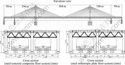
Fig.1 Main structures of WTC Bridge
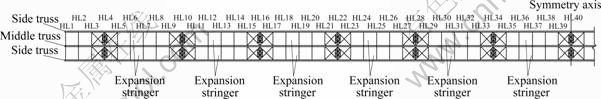
Fig.2 Plane view of arrangement of expansion stringers (one expansion stringer every six panels)
Table 1 Deflection and ratio of deflection to span under live load
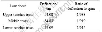
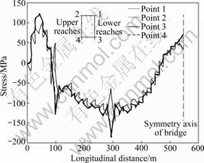
Fig.3 Stress of lower chords of middle truss under dead load and live load
The stresses of all the members of the trusses are less than 200 MPa. The stresses of the three trusses are similar, and the stress of the middle truss is a little larger than those of the other two. The stresses of the lower chords are larger than those of the other members of the trusses.
The maximum stress of the crossbeams is 215 MPa and takes place in crossbeam No.21 at the end connected to the middle truss. The steel stringers mainly bear the vertical load, and the horizontal bending is very small. The stresses of the stringers are less than 200 MPa.
The stresses of the concrete slab are small. Under live load, the maximum tensile stress is 1.18 MPa and takes place at the area close to the tower between stringer No.3 and No.4, while the maximum compression stress is -1.1 MPa and takes place in the fifth panel close to the centre of the main span. The maximum tensile stress and compression stress under the action of dead load and live load are 3 MPa and -6 MPa, respectively. Because high ratio of reinforcement is used in the slab, the crack width of the concrete slab will be less than 0.15 mm.
4 Main structure of NDC Bridge
NDC Bridge is about 20 km near the first Nanjing Yangtze River Bridge. The span of the main bridge is arranged as (108+192+336+336+192+108) m. The span of the side bridge is (84+84) m. The structure of the two 336 m spans is steel truss arch and the other spans are trusses [17]. The main structures are shown in Figs.6 and 7. Fig.8 shows the deck segment of NDC Bridge.
NDC Bridge has only one layer and six-line railways. The width of the bridge is 40.4 m, arranged as (5.2+15+15+5.2) m. Two of the six line railways are high-speed railways from Beijing to Shanghai which is located at 15 m on the lower reaches side and the other 15 m of the upper reaches side is arranged by the two- line Shanghai-Wuhan-Chengdu trunk railways. Outside 5.2 m is for metro light railway. The design speed of the high-speed railway is 300 km/h.
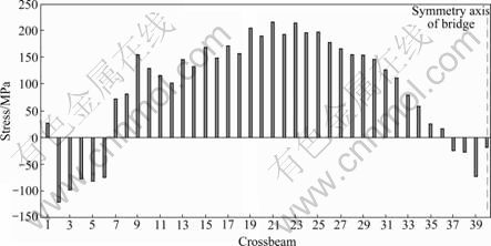
Fig.4 Maximum total stresses of 40 crossbeams under dead load and live load
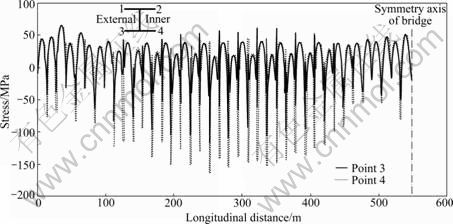
Fig.5 Total stress of stringer No.5 under dead load and live load
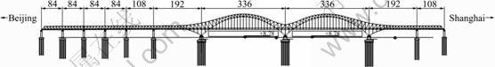
Fig.6 Elevation view of NDC Bridge (m)
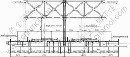
Fig.7 Cross section of NDC Bridge (mm)

Fig.8 Deck segment of NDC Bridge
The high-speed railways and the trunk railways are separated by the middle truss. The three trusses of the bridge are all N-shaped. The height of the steel truss is 16 m and the panel length is 12 m. The height of the truss arch of the main bridge varies from 12 to 54 m and the panel length from 12 to 15 m.
Three plans for the railway floor system are presented in the design. Plan 1 is concrete slab composited with the steel stringers and crossbeams. Plans 2 and 3 are all monolithic decks of steel orthotropic plates. In Plan 2, large stringers and large crossbeams are only arranged at the truss nodes. In Plan 3, three small crossbeams are arranged, which are connected with the lower chord of the truss in each panel besides the crossbeams at each node.
Comparisons of these three plans are made with respect to static behavior, construction, maintenance, high-speed running performance and material utilization amount. Finally, Plan 3 is used. In Plan 3, the height of the crossbeams arranged at nodes is 2.016 m, while that of the small crossbeams in panels is 1.392 m. Under each railway line, two stringers are arranged and the interval between them is 1.5 m. The height of the stringers is 0.496 m. Under the steel deck, longitudinal stiffeners are arranged. The webs of the crossbeams are opened at the place where the stringers and stiffeners pass through. The thickness of the monolithic steel decks is 16 mm.
5 3D finite element analysis of NDC Bridge
To study the behavior of NDC Bridge, 3D finite element analysis is done. The deflections and the ratios of deflection to span of the bridge under the action of live load are listed in Table 2. Because of the application of monolithic decks, the stiffness and structural integrity of NDC Bridge are high.
The total stresses of the steel components of the bridge under the action of dead load, live load and subsidiary load are all less than the allowable stress. Fig.9 shows the total stresses of the lower chord of upper reaches truss under dead load and live load.
3D FEM results show that the allocation of the loads acting on the deck in three trusses is different and varies in different places of the bridge. In order to analyze the allocating phenomenon conveniently, the load allocation in three trusses is divided into two steps, although they happen concurrently. Table 3 lists the ratio of the allocated loads acting on the deck of the three trusses in two spans, where the ratios mean the allocated load to the total load acting on one panel and are noted by γ1 and γ2 for step 1 and step 2, respectively. The first step allocation occurs on the floor system and the allocated load to the middle truss is much larger than that of the two side trusses. γ1 of the three trusses is nearly 1:3:1. Thus, there is a tendency that the deflection of the middle truss is to be larger than that of the side trusses. The second step allocation happens on the top lateral brace which pulls the middle truss nodes up and pushes the two side truss nodes down. The ratio of allocated loads in the second step are listed Table 3. It can be seen that γ2 is negative for the middle truss and positive for the two side trusses.
Table 2 Deflection and ratio of deflection to span under live load of NDC Bridge
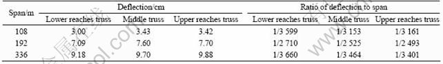
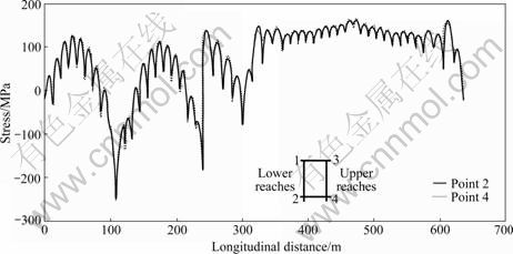
Fig.9 Total stresses of lower chord of upper reaches truss under dead load and live load
Table 3 Distribution of loads of three trusses of main bridge
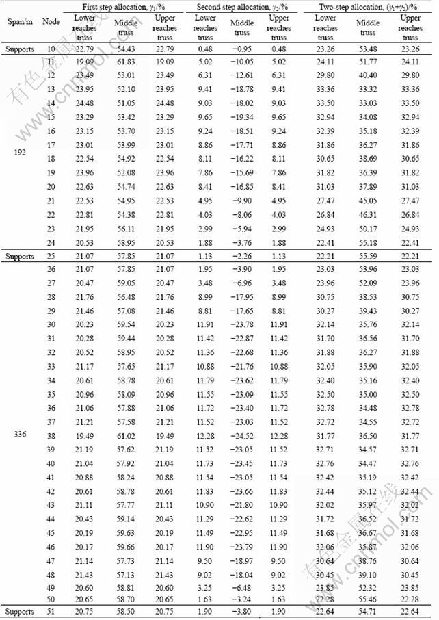
After the second step allocation, the differences of allocation loads among three trusses are decreased obviously and the differences of the deflections and axial forces of the three trusses are not too significant as those in step 1. It can also be seen that near the supports the loads allocated to the middle truss are nearly three times that of the side trusses, while in the middle of every span the allocated loads of the three trusses are almost equal.
Near the supports, although 60% of the loads are delivered to the middle truss, most of them are directly transferred from the truss to the supports. Therefore, this phenomenon does not influence the deflections and stress states of this bridge seriously. Thus, in the design, the loads are equally allocated to the three trusses, and then the members near the supports of the middle truss are strengthened according to the 3D analysis results.
Note that the loads delivered by the small crossbeams to the lower chords of the trusses are only involved in the first step allocation but not the second step allocation. Therefore, the moment and the bending stresses of the lower chords of the middle truss are nearly three times those of the side trusses.
6 Model experiments of NDC Bridge
Two segment models of 1:6 scale were made for NDC Bridge. One was six-panel truss segment and the other was six-panel arch segment. Experiment and 3D finite element analysis of the models were done. Fig.10 and Fig.11 show the finite element models and Fig.12 and Fig.13 show the experiment models of the truss segment and the arch segment, respectively. Seven load cases for each model were tested and analyzed. Fig.14 shows the longitudinal stresses of the tie beam of the arch segment model, and Fig.15 shows the deflection of lower chord of truss segment model. The 3D FEM results coincide with the test results. The load allocation ratio among three trusses is verified by the model experiments.

Fig.10 FEM model of truss segment
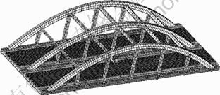
Fig.11 FEM model of arch segment
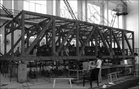
Fig.12 Truss segment model
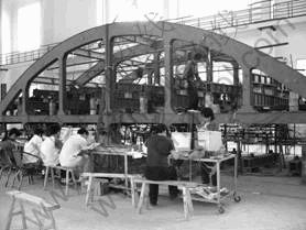
Fig.13 Arch segment model
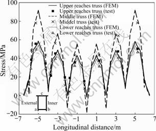
Fig.14 Longitudinal stress of tie beam of arch segment model under load case 1
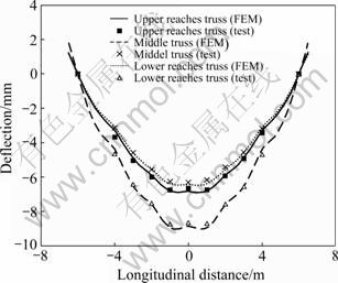
Fig.15 Deflection of lower chord of truss segment model under load case 1
7 Conclusions
1) Wuhan Tianxiangzhou Changjiang (WTC) Bridge is a cable-stayed bridge with steel-concrete composite railway ballasted floor system. In the design of this bridge, how to conform the deformations and stress levels of the railway floor system is one of the key
problems. After finite element analysis and comparison, the plan of arranging one expansion stringer every two panels is proposed and good effect is obtained.
2) Nanjing Dashengguan Changjiang Bridge is a six-line railway continuous steel truss arch bridge with monolithic deck of steel orthotropic plates. The allocation of the deck load among three trusses is one of the most important problems, which is studied using model experiment and 3D finite element analysis. The results of 3D FEM analysis coincide with model test results. It is shown that near the supports the load allocated to the middle truss is nearly three times that of the side trusses, while in the middle of every span the allocated loads of the three trusses are almost equal. In design, the loads are equally allocated to the three trusses, and then the members near the supports of the middle truss are strengthened according to the 3D analysis results.
3) The stiffness of these two bridges is sufficient. Because of the application of monolithic decks, the stiffness and structural integrity of NDC Bridge are high.
References
[1] ZHOU De, YE Mei-xin. Composite deck structure of large span through tied-arch bridge on high-speed railway [J]. Journal of Central South University: Science and Technology, 2009, 40(1): 256-262. (in Chinese)
[2] RYAN J L. Use of composite trusses in long-span power plant structures [C]// Proceedings of the 58th American Power Conference, Part 1. Chicago, 1996: 194-199.
[3] BETTI R, GJELSVIK A. Elastic composite beams [J]. Computers & Structures, 1996, 59(3): 437-451.
[4] BROZZETTI J. Design development of steel-concrete composite bridges in France [J]. Journal of Constructional Steel Research, 2000, 55(2): 229-243.
[5] SERACINO R, OEHLERS D J, YEO M F. Partial-interaction flexural stresses in composite steel and concrete bridge beams [J]. Engineering Structures, 2001, 23(9): 1186-1193.
[6] FAELLA C, MARTINELLI E, NIGRO E. Steel and concrete composite beams with flexible shear connection: “Exact” analytical expression of the stiffness matrix and applications [J]. Computers & Structures, 2002, 80(11): 1001-1009.
[7] ZHENG Jian. Key technologies for high speed railway bridge construction [J]. Engineering Science, 2008, 10(7): 18-27. (in Chinese)
[8] FANG Qin-han. Four double deck bridges for highway and railway over Changjiang River [J]. Journal of Railway Science and Engineering, 2004, 1(1): 10-13. (in Chinese)
[9] GAO Zong-yu. Large-span high-speed railway bridges across Yangtze River and Yellow River [J]. Engineering Sciences, 2009, 11(1): 17-21. (in Chinese)
[10] YI Lun-xiong. Engineering characteristic and key technique of Dashengguan Changjiang river bridge [J]. Steel Structure, 2007(5): 78-80. (in Chinese)
[11] LIU Gui-hong, YI Lun-xiong. Design of railway steel truss girder used with steel orthotropic deck plate [J]. Bridge Construction, 2007(S2): 8-10. (in Chinese)
[12] QIN Shun-quan, GAO Zong-yu, PAN Dong-fa. Key technology of Tianxingzhou Yangtze River Bridge [J]. Bridge Construction, 2007(1): 1-4, 20. (in Chinese)
[13] YU Zhen-ga, ROBINSONB D, TAYLORB S, CLELAND D. Finite element investigation of the structural behaviour of deck slabs in composite bridges [J]. Engineering Structures, 2009, 31(8): 1762-1776.
[14] ZHANG Ye-zhi. Mechanical state and improved method for the floor system of through steel truss semi-composite bridges [J]. China Railway Science, 2008, 29(2): 53-58. (in Chinese)
[15] Rail construction [2005]140. Temporary code for design of newly-built passenger dedicated railways with speed of 200-250 kilometres per hour [S]. (in Chinese)
[16] Rail construction [2004]157. Temporary code for design of Jinghu high-speed railway [S]. (in Chinese)
[17] ZHU Zhi-hu, YI Lun-xiong, GAO Zong-yu. Analysis of mechanical behavior and study of construction control measures of triple main truss structure of Dashengguan Changjiang River Bridge in Nanjing [J]. Bridge Construction, 2009(3): 1-4, 32. (in Chinese)
(Edited by YANG Bing)
Foundation item: Projects(2004G028, 2004G016) supported by the Science and Technology Development Program of Railways Department, China
Received date: 2010-01-27; Accepted date: 2010-06-17
Corresponding author: ZHANG Ye-zhi, Associate Professor, PhD, Tel: +86-731-82656954; E-mail: zhangyz824@163.com

