


Trans. Nonferrous Met. Soc. China 22(2012) 1381-1386
Ti-containing hydrogenated carbon films fabricated by high-power plasma magnetron sputtering
YANG Peng1, SUNG Chia-chi1, FUH Yiin-kuen2, CHU Chun-lin3, LO Chih-hung3
1. Department of Engineering Science and Ocean Engineering, National Taiwan University, Taipei;
2. Department of Mechanical Engineering, National Central University, Chung li;
3. National Nano Device Laboratories, Hsinchu
Received 17 October 2011; accepted 21 February 2012
Abstract: To improve the characteristics of a diamond-like carbon (DLC) film, Ti-containing amorphous hydrogenated carbon thin films were deposited on sus304 stainless steel substrates by high-power plasma-sputtering with titanium metal as the solid plasma source in a mixed ArC2H2 atmosphere. The films were fabricated to obtain a multilayered structure of Ti/TiC/DLC gradient for improving adhesion and reducing residual stress. The effects of substrate bias and target�Csubstrate distance on the films�� properties were studied by glow discharge spectroscope, X-ray diffractometer, Raman spectroscope, nanoindenter, and a pin-on-disk tribometer. The results indicate that the films possess superior adhesive strength and toughness.
Key words: high-power plasma-sputtering; Me-DLC; diamond-like carbon
1 Introduction
Diamond-like carbon (DLC) films have attracted a considerable attention because of their high hardness, optical transparency, low friction coefficient, chemical inertness, and high electrical resistivity. These properties make them useful in a wide range of applications, including low-friction and wear-resistant coatings, protective optical and biomedical coatings, electroluminescent materials, and field emission devices [1-5]. However, hard DLC coatings, which consist of a highly cross-linked network of carbon atoms, exhibit high compressive stress. This often leads to poor adhesion to the substrate, especially on steel, which limits the range of industrial applications and deposition thicknesses [6].
Researchers have used various methods to release the internal compressive stress in DLC films. Previous studies indicate that doping the films with additional elements can significantly reduce the internal stress. For example, Ti, Cr, Zr, W, Si, Al, Cu, and Fe are commonly used as dopants [7-10]. To date, these metals have been incorporated into the DLC matrix using sputter deposition [6-11], plasma-enhanced chemical vapor deposition [12], and ion-beam-assisted deposition [13,14]. Here, we examine magnetron sputtering, an important industrial coating process. In the recently developed technology of high-power plasma sputtering (HPPS), the source can reach very high plasma density of 1018 m-3 in front of the target with approximately 30%-70% ionization [15-17]. Those values are about an order of magnitude higher than those of conventional magnetron sputtering. The technique has proven to be useful for high-aspect-ratio filling applications and dense microstructures [18,19], and exhibits improved target utilization [20] and enhanced substrate pretreatment, which improves the adhesion of hard coatings [21,22]. High-power plasma magnetron sputtering (HPPMS) can easily be scaled up for industrial purposes.
In this work, an evaluation of carbon films deposited was presented using HPPMS. The Ti-DLC films have a multilayered structure of Ti/TiC/Ti with amorphous hydrogenated carbon (Ti-C:H). The Ti layer was added to improve the adhesion between film and substrate. The chemical composition of the TiC transition layer changes gradually from the interlayer to the DLC layer in order to reduce the stress and improve the crack resistance and microhardness. The substrate bias and target�Csubstrate distance were controlled during deposition in order to investigate the effect of bombardment energy on the structure of the Ti-C:H films.
2 Experimental
The Ti-C:H films were deposited by HPPMS using titanium metal as the solid plasma source in an mixed Ar-C2H2 atmosphere. A cross-sectional view of the HPPMS system is shown schematically in Fig. 1. Ti-C:H films were coated on polished sus304 stainless steel sheets of 600 mm��25 mm��2 mm. The stainless steel substrates were polished to an average roughness (Ra) of approximately 0.01 and ultrasonically cleaned in acetone for 30 min before being placed in the vacuum chamber. The substrates were placed on a rotating holder and maintained at the ambient temperature throughout the deposition process. The chamber was evacuated to a base pressure of approximately 6��10-4 Pa after a little Ar gas was leaked into the chamber. To remove any contamination, the metal targets and substrate were thoroughly cleaned by plasma bombardment at 0.3 Pa and high power. The Ti-C:H films were deposited in conjunction with pulse biasing on the steel substrates.
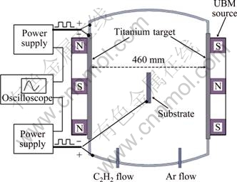
Fig. 1 Schematic of high-power plasma-sputtering system
The microstructure of the Ti-C:H films consisted of a titanium layer, a functional gradient layer of titanium carbide, and a Ti-DLC layer. Film deposition proceeded in four stages. At the pretreatment stage before deposition, HPPMS plasma was used to bombard and clean the substrate for 3 min. At the second stage, Ti film deposition, an interlayer, was created at a bias voltage of -100 V for 5 min to enhance the film adhesion. At the third stage, a functional gradient layer of TiC was deposited by varying the relative C2H2 flow between 0% and 25%. The gradient in the layer can reduce the internal stress by diminishing the mismatch between the thermal expansion coefficients of the Ti and the DLC. At the final stage, a Ti-DLC film having a low metallic content was deposited at a C2H2 flow of 25%. Varying the C2H2 flow can produce Ti-C:H films with a wide range of metal content. The total gas flow was 120 mL/min, and the working pressure was 0.3 Pa. The bias voltage varied from -50 V to -200 V, and the target-to- substrate distance ranged from 10 cm to 30 cm.
The thicknesses of films and crystal structures were measured by scanning electron microscopy (SEM) and X-ray diffraction (XRD), respectively. Chemical analyses were conducted using glow discharge spectroscopy (GDS, Leco GDS-750 QPD glow discharge optical spectrometer). The Raman spectroscopy was used to identify sp3/sp2 conversion and chemical bonds near the surface. The hardness of the coatings was determined by continuous stiffness measurement using a nanoindenter (MTS Nanoindenter XP). The coatings were scratch-tested using a pin-on-disk tribometer (RHESCA, CSR-101. The samples were scratched at a speed of 0.1 mm/s for a length of 15 mm, and the normal load was increased at a rate of 0.784 N/s. The characteristics of the coating failure were then examined by optical microscopy [23].
3 Results and discussion
3.1 Film layer analysis by GDS and XRD
Figure 2 shows the elemental composition and depth of the film determined by GDS. If the hydrogen atoms were ignored, it can be seen that the intended structure, Ti/TiC/Ti-DLC, was achieved. This is expected to solve the problems of high internal stress and poor adhesion of DLC films to metallic substrates. The Ti interlayer is expected to serve as a barrier that improves the adhesion between the carbon film and substrate. In the TiC gradient layer, the Ti atom content gradually decreased from the Ti interlayer to the boundary of Ti-DLC layer. The gradual change in chemical composition across this layer is expected to reduce growth-induced or thermally induced stress. Figure 3 shows the relationship among the Ti content, substrate bias, and target�Csubstrate distance. The results indicate that the target�Csubstrate distance has a greater effect on the Ti content than the substrate bias. Moreover, when the target to substrate distance is 15 cm, the thickness of Ti/TiC/Ti-DLC layers is the thickest, then the thickness decreases with increasing the distance. The GDS indicates that the Ti-DLC layer is about 7 ��m in thickness. The TiC layer is 1.1 ��m in thickness, and the Ti layer is approximately 4 ��m in thickness. Figure 4 shows the crystalline texture of a Ti-C:H film deposited at a bias voltage of -150 V, and the content of Ti was analyzed by GDS. A crystal wave crest appears on the Ti(100) and TiC(111) surfaces when the mole fraction of Ti in the Ti-C:H film reaches 32.3%, and on the Ti(100), Ti(101), TiC(111) and TiC(220) surfaces when the Ti content reaches 56%. When the Ti content is less than 20%, no crystal wave crest of Ti or Ti��C appears. Thus, this film is non-crystalline, and Ti atoms appear separately in Ti��Ti or Ti��C bonds. In Ti-C:H films with more than 32.3%Ti, the Ti atoms are distributed in a matrix that forms polycrystal Ti and TiC crystals. Therefore, as the Ti content increased during deposition, Ti atoms were initially distributed in non-crystalline Ti��Ti and Ti��C bonds in the carbon backing and subsequently appeared as crystalline Ti and in crystalline Ti-C. The XRD measurements reveal that the crystalline Ti and TiC phases coexist in the films with 56%�C58% Ti, which are composed of nanocrystalline grains embedded in an amorphous matrix.

Fig. 2 Quantitative GDS depth profile of Ti-C:H coating produced by HPPS (DLC-Ti on sus304, power 2 kW, bias voltage -100 V, 17.5 cm distance from target)

Fig. 3 Ti content of Ti-C:H coatings versus negative bias and target�Csubstrate distance (Ti-C:H on sus304 by HIPIMS, power 2 kW)

Fig. 4 X-ray diffraction patterns of Ti-C: H films with different target-substrate distances (Bias voltage -150 V, by HPPMS on sus304)
3.2 Raman spectra analysis
Raman spectra of all the films were observed between 1000 and 1800 cm-1, as shown in Fig. 5. The G peak is due to bond stretching of sp2 pair atoms in both rings and chains, and the D peak is due to the breathing modes of sp2 atoms in rings [24]. Results from the Refs. [25,26] indicate that the band intensity ratio I(D)/I(G) is inversely proportional to the sp3/sp2 ratio of carbon bonding. Therefore, the sp3 fraction of the films can be calculated from the wavenumber and intensity of the G and D peaks. As the sp3 fraction decreased, the G peak moved to higher wavenumber, and I(D)/I(G) increased. The G peak position and the intensity ratio I(D)/I(G) were calculated for the Raman spectra and plotted in Fig. 6. The results show that as the bias voltage increases, the position of the G peak shifts to a higher wavenumber, and I(D)/I(G) increases. Thus, at a greater bias, the number of sp3 bonds in the DLC component decreased, and sp2 bonds in the graphite phase dominated the structure. A Ti-C:H film is an intercrossing chain that contains non-crystalline carbon, crystalline Ti, and TiC. During growth, C��H bonds are easily broken by impacts from atoms. However, the breakage of C��H bonds can decrease the number of sp3-bonded carbon sites, resulting in the formation of C��Ti bonds, which was indicated by Raman spectroscopy analysis with increasing bias voltage. Thus, this work revealed that the bias voltage determines the film structure, and the intrinsic stress can evidently be released through Ti doping, at the expense of a reduction of the sp3/sp2 ratio.

Fig. 5 Raman spectra of Ti-C:H films between 1000 cm-1 and 1800 cm-1 with peak appearing at 1550 cm-1 (Ti-C:H, bias voltage -125 V, distance 25 cm, by HPPMS on sus304)
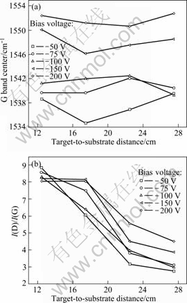
Fig. 6 G peak position (a) and I(D)/I(G) (b) with respect to substrate bias for Ti-C:H films (Ti-C:H on sus304 by HIPIMS, power 2 kW, 110 mL/min Ar, 12 mL/min C2H2)
3.3 Hardness measurement by nanoindenter
Figure 7 shows the hardness versus the substrate bias voltage and target�Csubstrate distance. The hardness of the coating increased with the substrate bias. The maximum (22.5 GPa) and minimum hardness (11 GPa) occurred at the substrate bias voltages of -200 V and -50 V, respectively. As the bias voltage increased, the greater bombardment energy provided sufficient kinetic energy for incoming ions to break C��H bonds. Ti ions displaced the hydrogen atoms, forming stable Ti��C carbide bonds and Ti��Ti bonds. Therefore, under high-energy bombardment, the degree of cross-linking within the film increased, making the film structure dense and improving the film��s hardness. A high value implies a higher bonding energy between atoms, a longer bonding distance between atoms, higher ionic content, and greater metallic bonding. Because the Ti-C:H films contained metal, they had a stronger cohesive force and greater tenacity but low rigidity.
3.4 Scratch analysis
Figure 8(a) shows the transformation curves for the scratch test. In samples having a target�Csubstrate distance of 10 cm and 15 cm, the onset of frictional force is evident in abrupt variations at a normal load of approximately 27.4 N, which constitutes adhesive failure. The optical micrographs of a scratch in Figs. 8(b) and (c) show that the film is not completely broken. In the other samples, the friction force did not show an abrupt onset. When the mole ratio of Ti to C exceeded 0.5, the film consisted of nanocrystalline grains embedded in an amorphous matrix. The film surface was rough, which increased the frictional force to cause adhesive failure (e.g., at 2.74 N load). When the mole ratio of Ti to C was lower than 0.4 at a target�Csubstrate distance of 25 cm or 30 cm, the carbon film showed good lubrication, and the stainless substrate was soft. Hence, the carbon film adhered strongly to the substrate under a normal force. This study confirms the superior adhesive strength and toughness of Ti-C:H films produced by HPPMS.

Fig. 7 Relationship between bias voltage and target-to-substrate distance and hardness for Ti-C:H films (Ti-C:H on sus304 by HPPMS, power 2 kW, 12 mL/min C2H2, 110 mL/min Ar)

Fig. 8 Transformation curves for scratch test of DLC film deposited at bias voltage of -125 V, with different target�Csubstrate distances (a), and optical micrographs of adhesive failure of films (b) and (c) (Ti-C:H, bias voltage 125 V, power 2.5 kW by HPPMS on sus304)
4 Conclusions
1) The characteristics of a Ti-containing DLC film deposited by HPPMS on sus304 stainless steel were studied using titanium metal as the solid plasma source in a mixed Ar-C2H2 atmosphere. The substrate bias voltage and target�Csubstrate distance were used as indexes. The mole ratio of Ti to C atoms remained stable at the target �Csubstrate distance of 10�C15 cm. However, at the distance of 15�C30 cm, the ratio clearly decreases as the distance increases.
2) The bias voltage has a smaller effect on the mole ratio of Ti to C. The mole ratio of Ti to C ratio, in turn, affects the structure of the films. As the Ti content increases, the non-crystalline Ti-C:H film more closely resembles a DLC film. Ti and carbonized crystalline Ti are distributed throughout the non-crystalline carbon, increasing the tenacity of the film. The rigidity of the films increases gradually with the bias voltage.
3) Raman spectroscopy shows that the wave crest of the G band moves toward higher wavenumber, and the intensity ratio of the D and G bands, I(D)/I(G), increases with increasing the bias voltage. This evidently reflects a decrease in the number of sp3 bonds in the DLC component as sp2 bonds in the graphite phase begin to dominate the structure. The hardness and scratch test results indicate that the obtained Ti-C:H films exhibit superior adhesive strength and toughness.
References
[1] KINOSHITA H, IPPEI I, SAKAI H, OHMAE N. Synthesis and mechanical properties of carbon nanotube/diamond-like carbon composite films [J]. Diamond and Related Materials, 2007, 16: 1940-1944.
[2] LADWIG A M, KOCH R D, WENSKI E G, HICKS R F. Atmospheric plasma deposition of diamond-like carbon coatings [J]. Diamond and Related Materials, 2009, 18: 1129-1133.
[3] MARCIANO F R, BONETTI L F, LIMA-OLIVEIRA D A, MELLO C B, UEDA M, CORAT E J, TRAVA-AIROLDI V J. Characterization of crystalline diamond incorporated diamond-like carbon films [J]. Diamond and Related Materials, 2010, 19: 1139-1143.
[4] SMIETANA M, SZMIDT J, KORWIN-PAWLOWSKI M L, MILLER N, ELMUSTAFA A A. Influence of RF PACVD process parameters of diamond-like carbon films on optical properties and nano-hardness of the films [J]. Diamond and Related Materials, 2008, 17: 1655-1659.
[5] WEI C, WANG C I, TAI F C, TING K, CHANG R C. The effect of CNT content on the surface and mechanical properties of CNTs doped diamond like carbon films [J]. Diamond and Related Materials, 2010, 19: 562-566.
[6] HE F, WONG P L, ZHOU X. Wear properties of DLC-coated steel rollers running with highly contaminated lubrication [J]. Tribology International, 2010, 43: 990-996.
[7] JONES B J, ANGUILANO L, OJEDA J J. Argon plasma treatment techniques on steel and effects on diamond-like carbon structure and delamination [J]. Diamond and Related Materials, 2011, 20: 1030-1035.
[8] AHMED S F, BANERJEE D, CHATTOPADHYAY K K. The influence of fluorine doping on the optical properties of diamond-like carbon thin films [J]. Vacuum, 2010, 84: 837-842.
[9] TAKENO T, SUGAWARA T, MIKI H, TAKAGI T. Deposition of DLC film with adhesive W-DLC layer on stainless steel and its tribological properties [J]. Diamond and Related Materials, 2009, 18: 1023-1027.
[10] WANG A Y, LEE K R, AHN J P, HAN J H. Structure and mechanical properties of W incorporated diamond-like carbon films prepared by a hybrid ion beam deposition technique [J]. Carbon, 2006, 44: 1826-1832.
[11] WU W Y, TING J M. Growth and characteristics of metal-containing diamond-like carbon using a self-assembled process [J]. Carbon, 2006, 44: 1210-1217.
[12] CASCHERA D, COSSARI P, FEDERICI F, KACIULIS S, MEZZI A, PADELETTI G, TRUCCHI D M. Influence of PECVD parameters on the properties of diamond-like carbon films [J]. Thin Solid Films, 2011, 519: 4087-4091.
[13] PARK Y J, SOBAHAN K M A, HWANGBO C K. Optical and structural properties of Fe2O3 thin films prepared by ion-beam assisted deposition [J]. Surface and Coatings Technology, 2009, 203: 2646-2650.
[14] LEE C K. Wear-corrosion behavior of ultra-thin diamond-like carbon nitride films on aluminum alloy [J]. Diamond and Related Materials, 2008, 17: 306-312.
[15] GUDMUNDSSON J T. The high power impulse magnetron sputtering discharge as an ionized physical vapor deposition tool [J]. Vacuum, 2010, 84: 1360-1364.
[16] GRECZYNSKI G, JENSEN J, B?HLMARK J, HULTMAN L. Microstructure control of CrNx films during high power impulse magnetron sputtering [J]. Surface and Coatings Technology, 2010, 205: 118-130.
[17] GUDMUNDSSON J T, ALAMI J, HELMERSSON U. Evolution of the electron energy distribution and plasma parameters in a pulsed magnetron discharge [J]. Applied Physics Letters, 2001, 78: 3427-3429.
[18] ANDR? A, Discharge physics of high power impulse magnetron sputtering [J]. Surface and Coatings Technology, 2011, 205(Supplement 2): S1-S9.
[19] LATTEMANN M, HELMERSSON U, GREENE J E. Fully dense, non-faceted 111-textured high power impulse magnetron sputtering TiN films grown in the absence of substrate heating and bias [J]. Thin Solid Films, 2010, 518: 5978-5980.
[20] KOUZNETSOV V, MAC?K K, SCHNEIDER J M, HELMERSSON U, PETROV I. A novel pulsed magnetron sputter technique utilizing very high target power densities [J]. Surface and Coatings Technology, 1999, 122: 290-293.
[21] LATTEMANN M, EHIASARIAN A P, BOHLMARK J, PERSSON P ? O, HELMERSSON U. Investigation of high power impulse magnetron sputtering pretreated interfaces for adhesion enhancement of hard coatings on steel [J]. Surface and Coatings Technology, 2006, 200: 6495-6499.
[22] EHIASARIAN A P, HOVSEPIAN P E, HULTMAN L, HELMERSSON U. Comparison of microstructure and mechanical properties of chromium nitride-based coatings deposited by high power impulse magnetron sputtering and by the combined steered cathodic arc/unbalanced magnetron technique [J]. Thin Solid Films, 2004, 457: 270-277.
[23] CAICEDO J C, AMAYA C, YATE L, NOS O, GOMEZ M E, PRIETO P. Hard coating performance enhancement by using [Ti/TiN]n, [Zr/ZrN]n and [TiN/ZrN]n multilayer system [J]. Materials Science and Engineering B, 2010, 171: 56-61.
[24] CASIRAGHI C, FERRARI A C, ROBERTSON J. Raman spectroscopy of hydrogenated amorphous carbons [J]. Physical Review B, 2005, 72: 085401.
[25] FERRARI A C, ROBERTSON J. Interpretation of raman spectra of disordered and amorphous carbon [J]. Physical Review B, 2000, 61: 14095-14107.
[26] SCHWAN J, ULRICH S, BATORI V, EHRHARDT H, SILVA S R P. Raman spectroscopy on amorphous carbon films [J]. Journal of Applied Physics, 1996, 80: 440-447.
�߹��ʵ����Ӵſؽ��䷨�Ʊ���������ʯ̼Ĥ
YANG Peng1, SUNG Chia-chi1, FUH Yiin-Kuen2, CHU Chun-lin3, LO Chih-hung3
1. Department of Engineering Science and Ocean Engineering, National Taiwan University, Taipei;
2. Department of Mechanical Engineering, National Central University, Chung-li;
3. National Nano Device Laboratories, Hsinchu
ժ Ҫ��Ϊ�˸�������ʯ̼Ĥ�����ܣ����ø߹��ʵ����Ӵſؽ��䷨�����ѷǾ�̼��Ĥ������304����ֻ����ϣ���ԴΪC2H2-Ar������壬������Ϊ�����вġ�Ϊ�˸��Ƹ������ͽ��Ͳ���Ӧ�����Ʊ��˺�Ti/TiC/DLC���ṹ�Ķ�Ĥ������GDS��XRD��SEM��Raman����������ѹ���Ǻ���-��Ħ�����о�����ƫѹ��������вĵľ���Ա�Ĥ���ܵ�Ӱ�졣�����������Ĥ����������ճ��ǿ�Ⱥ����ԡ�
�ؼ��ʣ��߹��ʵ����Ӵſؽ��䣻����-����ʯ̼Ĥ������ʯ̼Ĥ
(Edited by LI Xiang-qun)
Corresponding author: CHU Chun-lin; Tel: +886-3-4267-377; Fax: +886-3-4254-501; E-mail: jenlen.boy@msa.hinet.net
DOI: 10.1016/S1003-6326(11)61329-0

