J. Cent. South Univ. Technol. (2011) 18: 16-22
DOI: 10.1007/s11771-011-0652-3

Continuous FEM simulation of multi-pass plate hot rolling suitable for plate shape analysis
ZHANG Jin-ling(张金玲), CUI Zhen-shan(崔振山)
National Die and Mold CAD Engineering Research Center, Shanghai Jiao Tong University, Shanghai 200030, China
? Central South University Press and Springer-Verlag Berlin Heidelberg 2011
Abstract: In order to continuously simulate multi-pass plate rolling process, a 3-D elastic hollow-roll model was proposed and an auto mesh-refining module with data passing was developed and integrated with FE software, Marc. The hollow-roll model has equivalent stiffness of bending resistance and deformation to the real solid and much less meshes, so the computational time is greatly reduced. Based on these, the factors influencing plate profile, such as the roll-bending force, initial crown, thermal crown and heat transfer during rolling and inter-pass cooling can be taken into account in the simulation. The auto mesh-refining module with data passing can automatically refine and re-number elements and transfer the nodal and elemental results to the new meshes. Furthermore, the 3-D modeling routine is parametrically developed and can be run independently of Marc pre-processing program. A seven-pass industrial hot rolling process was continuously simulated to validate the accuracy of model. By comparison of the calculated results with the industrial measured data, the rolling force, temperature and plate profile are in good accordance with the measured ones.
Key words: multi-pass rolling; continuous simulation; equivalent hollow roll; mesh refinement; data passing; plate shape
1 Introduction
Plate shape is an important quality index of plate products, which determines the market competitiveness of plate [1-2]. Growing demand for shape accuracy drives the constant development of shape control technique [3-5]. Being at a lower level, however, offline simulation of shape cannot meet industrial requirement due to the complexity of shape influence factors.
FEM simulation of rolling processes is one of the most effective methods to reduce the risk of online debugging and to improve the shape accuracy. Many approaches were implemented to predict the rolling force [6-7], temperature [8-9] as well as microstructure [10-11]. However, plate shape is determined by the joint effect of factors such as elastic flattening and deflection of the roll as well as the initial crown and thermal deformation. Therefore, if the plate shape is addressed, a deformable roll model should be involved in the rolling simulation. However, the dimension of roll is usually much bigger than that of the plate, so the deformable roll model will produce great number of meshes and make the computation time too long. In addition, for the multi-pass hot rolling process, the working parameters especially the temperature change continuously, which requires that the simulation should be continuous. But, because of the large elongation in rolling direction, for continuous simulation of multi-pass rolling, the mesh should be refined many times, thus it will cause nodal and elemental multi-transformation in the formation between new meshes and the old ones during simulation. This transformation must be automatically implemented during the simulation running, otherwise it will break down the simulation process and cause great work load. Due to the above difficulties, vast rolling simulations by using FEM were still limited to single pass process, with only very few extended to multi-pass rolling [12-13]. In most of the researches, the roll was built as rigid body and elastic deformation of roll was ignored [14-15]; therefore, it is not suitable to predict plate shape.
In order to fully consider all the influence factors on the plate shape, a 3-D thermo-mechanical coupled elasto- plastic FE model was established based on commercial FEM code, Marc. An equivalent hollow roll model was developed to replace solid roll to save calculation time. Moreover, a FE model generation module was developed to parametrically generate the FE model for multi-pass rolling and transfer the calculation results of the former pass to be the initial conditions of the follow-up pass. Also, in this module, the mesh refinement between passes is automatically implemented, and the initial conditions on the new mesh are automatically generated by interpolation or extrapolation method, so that the continuous simulation is realized successfully.
2 FE model
2.1 Equivalent hollow roll model
To reduce the volume of the roll to be meshed and keep its deformation behavior to undertake the rolling force, an equivalent hollow roll was established. In order to get the same elastic flattening and bending deflection as the actual solid roll, the equivalent one is composed of two layers, as illustrated in Fig.1. The outer layer has the same material property as the actual roll, by which the elastic flattening behavior is remained; while the inner layer has a corresponding larger elastic modulus to keep the hollow roll to act as actual roll in bending response. According to the mechanics of materials, the bending deflection is guaranteed by the following equation:
 (1)
(1)
where w is the deflection, M(x) is the bending moment, E is the elastic modulus, and I is the second moment of area. It can be seen that deflection of the roll will remain unchanged if the EI does not change in the substitution of hollow roll for actual roll.
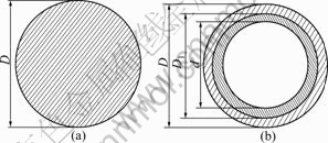
Fig.1 Section of hollow roll and solid roll: (a) Solid roll; (b) Equivalent hollow roll
For solid roll: 
For outer layer of the hollow roll:


For inner layer of the hollow roll:


The equivalent bending deflection requires that the following equation must be satisfied:
 (2)
(2)
where E denotes the elastic modulus of solid roll, and Ek is the equivalent elastic modulus of the inner layer of the hollow roll.
The above equations yield the following solution:
 (3)
(3)
Fig.2 compares the stress distribution in equivalent hollow roll and in actual solid one, in which the two rolls show very similar stress pattern in the contact area so the flattening effects of the two rolls are also equivalent.
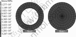
Fig.2 Comparison of stress status between hollow and solid roll under same deformation conditions
Deflection of solid roll and equivalent hollow roll under the same deformation conditions is depicted in Fig.3, which shows that two deflection curves are close to each other and the equivalent roll satisfies the requirement of deflection equivalence.
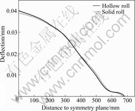
Fig.3 Comparison of deflection between hollow and solid roll under same deformation conditions
Figs.2 and 3 demonstrate that the so-built hollow roll is equivalent to the actual solid roll in deformation behavior.
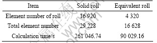
Table 1 compares the element number and calculation time for a single pass simulation by solid roll model and equivalent hollow roll model. It can be seen that by using equivalent hollow roll model the element number and computational time are greatly reduced.
Table 1 Comparison of element number and calculation efficiency
2.2 Parametric generation of models
Because the practical model is in symmetry, it is enough to build a quarter of it in simulation. Moreover, during multi-pass rolling process, models from each pass have the same geometric characteristic. Therefore, parametric module is developed to build models parametrically instead of building through pre-processing interface of FEM software and to save modeling time significantly. Users only need to input roll diameter, initial crown value, body length, etc, into the input file, and models will be produced automatically.
Taking the equivalent hollow roll model for example, which is in an axial symmetry, first 2-D FE model on the meridian plane was built, as shown in Fig.4. In order to involve the initial crown of the roll, a parabola was taken to describe the outline of the roll body. Then, it was rotated revolving the symmetry axis to expand into 3-D model.

Fig.4 Two-dimensional model of roll
It was divided into 5 parts with different mesh densities along the axis; especially in the contact area between plate edge and the roll, mesh density is much higher than other areas in order to study the edge drop phenomena. Labels in Fig.4 such as NW1, NELR are divided number of each part. The generation of plate followed the same law. Moreover, because both roll and plate are regular, eight-node hexahedral elements were adopted.
2.3 Driving of roll and exerting of bending force
Model of the roll is flexible in this simulation, so its rotation is driven by a rigid plane gluing to the roll head through two control nodes, as shown in Fig.5. The rigid plane has the same deformation of freedom (DOF) with the control nodes. Rotational load is put on control node 2, and bending force is applied to control node 1 at center. Therefore, the rotation of the roll and the bending deflection are realized simultaneously.
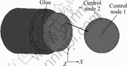
Fig.5 Sketch map of roll rotation through control nodes
3 Continuous simulation of multi-pass rolling
3.1 Mesh refinement
After multi-pass deformation, elements of the plate will be distorted, which will cause low precision of the solution. So, mesh should be refined. Still, there is no proper method to refine hexahedron element in the present FEM software including Marc. In the present work, a mesh refinement method is developed for hexahedron element, which fits for models like plate. Depressed deformation and extensional deformation are the main styles during rolling, so interior angle and aspect ratio can be adopted as criteria of mesh refinement.
If the aspect ratio is out of the range, elements should be refined along the rolling direction, and coordination of new nodes can be obtained through interpolation:
 (4)
(4)
where I is the number of the present node, NZ is the difference of node number on adjacent rows along the rolling direction, X is the coordination of original node on old mesh and x is that of the new one.
When the interior angle is not satisfied, node coordination can be recalculated as follows according to the deformation characteristic of plate:
XN0+j=XN0, j=1, NZ-1 (5)
where N0 is initial node number of each row.
Comparison of elements before and after refinement is shown in Fig.6. After refinement, aspect ratio and inner angle have been improved efficiently.

Fig.6 Comparison of mesh shape before and after refinement: (a) Aspect ratio improvement; (b) Interior angle improvement
3.2 Transfer of parameters
In order to keep the continuity of the simulation, model of subsequent pass is built according to the former pass not only to inherit the geometry dimensions but also to inherit the process parameters such as temperature. Through a post-processing subroutine, the nodal or elemental values of the old mesh are stored in an intermediate file. When the new mesh is created for the next pass, these values are restored as the initial conditions. If the mesh is refined, the nodal values at the new node are calculated by inter- or extra-polation method from the intermediate file and are assigned as the initial conditions. Therefore, the continuous computation of multi-pass is accomplished.
All the above procedures are executed in the background through batch file without calling the pre-processing code of FEM software.
4 Application and discussion
4.1 Simulation
As an application, an industrial seven-pass plate hot rolling process is simulated. The rolling schedule is given in Table 2, where TE is entrance thickness, RR is reduction ratio, DR is roll diameter, VR is rolling velocity, and FB is bending force.
Table 2 Rolling schedule
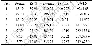
Initial thickness and width of the slab are 48.59 mm and 1 298 mm, respectively, and contact arc length of the first pass is about 89.16 mm. In order to guarantee the precision of solution as well as save computation cost, the length of the plate model is set as 900 mm. The plate is run along the negative direction of Z axis in the simulation.
According to the practical rolling condition, flow stress of the plate adopted here is studied at the strain rates of 5, 10, 20 and 30 s-1 and at the temperatures of 800, 900, 1 000 and 1 100 ℃ through Gleeble-1500 thermo- mechanical physical simulator. The test data are compiled into a material property database and calculated by FEM code Marc.
4.2 Force
Fig.7 shows the unit contact force and friction force along contact arc of passes 1, 3 and 5.
Unit friction force is in the same direction with rolling in backward slip zone that is along negative direction of Z axis, so it is the driving force of plate. But with the flow of metal, friction turns to the opposite
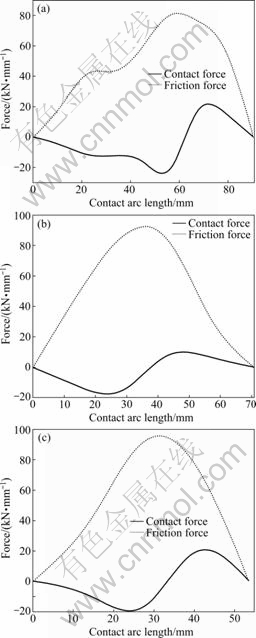
Fig.7 Distributions of contact force and friction force along contact arc: (a) Pass 1; (b) Pass 3; (c) Pass 5
direction at neutral plane, so it becomes resistance force of plate in forward slip zone. The rolling force increases with the reduction ratio. Because flow stress is not a constant value here, the maximum value of contact force does not occur just on neutral plane like result from traditional research but at both sides, so there are two peak points there.
Fig.8 compares the simulated and measured rolling force, and maximal difference is seen at the 7th pass with an error of about -8.09%.
4.3 Temperature
Fig.9 demonstrates the simulated temperature at the plate surface and central layer, and the surface temperature is compared with the measured value. It is seen that the surface temperature drops dramatically when running into the roll-gap due to the contact to the chilly roll, and rises quickly after running out of the roll-gap due to the heat transfer from central layer. While the central temperature rises a little when it is in the gap due to the plastic deformation heat, and drops slowly when it is out of the gap due to the heat transfer. When the plate gets thinner, the temperature difference between surface and central layer gets smaller.
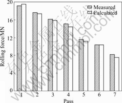
Fig.8 Comparison between measured and calculated rolling force
4.4 Deformation
4.4.1 Plate crown
Crown is a characteristic describing thickness distribution along the plate width. Fig.10 shows the plate thickness of passes 1, 3, 6 and 7.
Because of the positive crown of the roll, the negative crown is found at the centerline area, which is in coincidence with the actual plate profile. The crown drops with the reduction ratio decreasing, as shown in Table 2. At pass 7 there is only a tiny local central negative crown at about -22 μm.
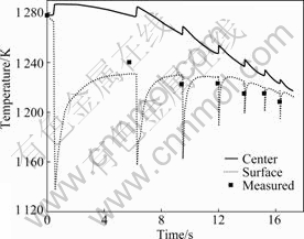
Fig.9 Comparison between measured and calculated plate temperature
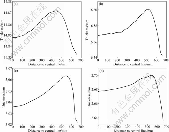
Fig.10 Distributions of plate thickness along width: (a) Pass 1; (b) Pass 3; (c) Pass 6; (d) Pass 7
From Fig.10, we can see that all the passes have edge drop area, so there is overall positive crown in all the passes, which is in agreement with the industrial situation. This is mainly attributed to the plane stress characteristic at the edge. At pass 7, the overall positive crown is about 30 μm.
4.4.2 Plate shape curve
The main factor affecting plate shape is the distribution of residual stress along the width, which is known as the plate shape curve. Perfect plate shape curve is a zero line, and in this case warp or wave shape will not occur [2]. Fig.11 illustrates the plate shape curves for passes 1, 3, 6 and 7.
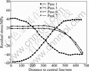
Fig.11 Plate-shape curves for passes 1, 3, 6 and 7
Since initial crown of plate has not been taken into account before rolling, after the first pass a negative convexity occurs and the corresponding plate-shape curve shows central buckle. In the following pass, plate-shape curves present double edge wave with a reduced negative convexity.
4.4.3 Side profile at edge
During flat rolling, uneven lateral spread will induce convex or concave shape at edge section. PAWELSKI and PIBER [16] summarize the condition of different edge section shapes when rolling plate has rectangle edge. According to their theory, when  <0.68, concave side profile happens; when >0.68 convex side profile happens.
If the plate has an initial convex profile at side edge before rolling, it is more likely to result in a further convex profile.
Parameters of side edge profile of passes simulated are displayed in Table 3, and are found to be greater than 0.68 for all the passes.
Fig.12 shows the profiles of side edge for passes. All of them are convex. The model of next pass is built on the basis of the former one, so the convex degree of
Table 3 Side edge profile parameter
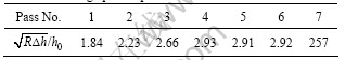
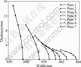
Fig.12 Section shape at edge
the next pass is higher than the former one, as shown in Fig.12.
From the simulation results, one can see that, in order to improve the final plate shape, reduction of the first four passes can be set a little larger so that plate crown can be adjusted to the greatest extent. Furthermore, negative roll bending force in the former passes can be reduced to some extent and positive value in the last passes can be increased appropriately to improve edge drop situation. In addition, rolling schedule can be adjusted appropriately in order to obtain rectangular section.
5 Conclusions
1) In order to predict plate shape and to improve the rolling schedule, a continuous simulation system of plate for multi-pass hot rolling is developed. The systems are composed of two meaningful parts. First, an equivalent hollow roll model is developed to replace the solid one, which saves computation time significantly under the premise of ensuring accuracy. Second, a module is created to generate the simulation model and transfer the state parameters from foregoing pass results to the following pass model, thus makes it possible to simulate multi-pass rolling continuously.
2) As an application, an industrial 7-pass hot rolling process of plate is simulated. The results demonstrate a good coincidence to the industrially measured data and the validity of the simulation system. The simulation results show a way for obtaining good plate crown, plate-shape curve as well as side edge profile by improving the rolling schedule.
References
[1] HWANG S M, SUN C G, RYOO S R. An integrated FE process model for precision analysis of thermo-mechanical behaviors of rolls and strip in hot strip rolling [J]. Computer Methods in Applied Mechanics and Engineering, 2002, 191(37/38): 4015-4033.
[2] LIU Hong-min, DING Kai-rong, LI Xing-dong, JIANG Guang-biao. Theoretical computational method of shape standard curve [J]. Chinese Journal of Mechanical Engineering, 2008, 44(8): 137-142. (in Chinese)
[3] SHAO Jian, HE An-rui, YANG Quan, SHI Nai-an. Simulation and application of shape set control system in hot tandem rolling mill [J]. Journal of Iron and Steel Research, 2008, 20(6): 53-56. (in Chinese)
[4] YU H L, LIU X H, LEE G T, PARK H D. Numerical analysis of strip edge drop for Sendzimir mill [J]. Journal of Materials Processing Technology, 2008, 208(1/2/3): 42-52.
[5] ISHIKAWA T, YUKAWA N, TOZAWA Y. Optimization of pass schedule from the view point of shape and profile of cold rolled strip [J]. CIRP Annals-Manufacturing Technology, 1989, 38(1): 257-260.
[6] YU Hai-liang, ZHAO Xian-ming, LIU Xiang-hua. Tri-dimensional elastic-plastic FEM of rolling force during strip finishing rolling process [J]. Research on Iron & Steel, 2005, 33(1): 14-16. (in Chinese)
[7] DONG Hong-bo, KANG Yong-lin. Prediction model for rolling force parameters during rolling of medium and heavy plate [J]. Special Steel, 2004, 25(2): 6-8. (in Chinese)
[8] LIU Cai, CUI Zhen-shan. Thermo mechanical coupled finite-element modelling of slab hot rolling [J]. Chinese Journal of Mechanical Engineering, 1998, 34(4): 35-39. (in Chinese)
[9] REZA R, SIAMAK S. Three-dimensional model for hot rolling of aluminum alloys [J]. Materials and Design, 2007, 28(8): 2366-2372.
[10] XIAO Hong, XU Hong-biao, BI En-fu. Prediction of rolling loads, temperature and microstructure variation during hot strip rolling [J]. Iron & Steel, 2003, 38(9): 35-38. (in Chinese)
[11] JANG Y S, KO D C, KIM B M. Application of the finite element method to predict microstructure evolution in the hot forging of steel [J]. Journal of Materials Processing Technology, 2000, 101: 85-94.
[12] KOMORI K. Simulation of deformation and temperature in multi-pass three-roll rolling [J]. Journal of Materials Processing Technology, 1999, 92/93: 450-457.
[13] WANG Min-ting, ZANG Xin-liang, LI Xue-tong. Finite element simulation of hot strip continuous rolling process coupling microstructural evolution [J]. Journal of Iron and Steel Research, International, 2007, 14(3): 30-36.
[14] CHANDRA S, DIXIT U S. A rigid-plastic finite element analysis of temper rolling process [J]. Journal of Materials Processing Technology, 2004, 152: 9-16.
[15] JIANG Z Y, TIEU A K. A simulation of three-dimensional metal rolling processes by rigid-plastic finite element method [J]. Journal of Materials Processing Technology, 2001, 112: 144-151.
[16] PAWELSKI O, PIBER V. Possibilities and limits of deformation in width direction in hot flat rolling [J]. Stahl und Eisen, 1980, 100(17): 937-949.
(Edited by YANG Bing)
Foundation item: Project(20050248007) supported by the Specialized Research Fund for the Doctoral Program of Higher Education of China
Received date: 2009-08-24; Accepted date: 2010-01-11
Corresponding author: CUI Zhen-shan, Professor, PhD; Tel: +86-21-62827605; E-mail: cuizs@sjtu.edu.cn

