


Trans. Nonferrous Met. Soc. China 22(2012) 1568-1574
Prediction and optimization of end milling process parameters of cast aluminium based MMC
R. AROKIADASS, K. PALANIRADJA, N. ALAGUMOORTHI
Department of Mechanical Engineering, Pondicherry Engineering College,Puducherry-605 014, India
Received 17 October 2011; accepted 21 February 2012
Abstract: The machining characteristics of LM25 Al/SiCp composite using end milling was investigated. A comprehensive mathematical model was developed for correlating the interactive and higher order influences of various process parameters on the dominant machining criteria, i.e. the tool flank wear phenomena, through response surface methodology, utilizing relevant experimental data obtained through experimentation. Experimental plan was performed by a standard response surface methodology design called a central composite design (CCD). The results of analysis of variance (ANOVA) indicate that the proposed mathematical model can adequately describe the performance within the limits of the studied factors. Optimal combination of these parameters can be used to achieve the minimum tool flank wear.
Key words: end milling; metal matrix composite (MMC); response surface methodology; optimization
1 Introduction
The performance of machining is measured in terms of cutting forces, tool wear, power consumption, and surface finish. In machining, surface finish plays an important role as it influences the functional properties of the machined components. There are a number of factors, such as cutting conditions, tool geometry, work material characteristics, and cutting fluid, which affect the tool flank wear and surface finish.
End milling process is classified as material removal process. This process and its machine tools are capable of producing complex shapes with the use of multi tooth cutting tools. In the end milling process, a multi tooth cutter rotates along various axes with respect to the workpiece. Wear on the flank of a cutting tool is caused by friction between the newly machined workpiece surface and the contact area on the tool flank. Because of the rigidity of the workpiece, the worn area referred to the flank wear land, must be parallel to the resultant cutting direction. The width of the wear land is usually taken as a measure of the amount of wear and can be readily determined by means of a toolmaker��s microscope. In the end, excessive flank wear will lead to poor surface texture, inaccuracy and increasing friction as the edge shape changes [1].
Metal matrix composites (MMC) are a relatively new class of materials characterized by lower density and greater strength and wear resistance than the conventional materials. Due to their superior strength and stiffness, MMCs have good potential for application in the automotive and aerospace industries [2�C4]. The machining of MMCs is very difficult due to the highly abrasive and intermittent nature of the reinforcements. Conventional tool materials, such as high-speed steel, cannot be used for MMCs as the cutting tool undergoes very rapid wear. Carbides, either plain or coated, sustain significant levels of tool wear after a very short period of machining [5].
To study the difficulties in machining of MMCs, previous investigations on the machinability of MMCs have covered the effects of machining parameters and the properties of MMCs on the tool wear and the mechanism of the tool wear. CHENNAKESAVARAO et al [6] experimented with different cutting tools. They reported that the crater wear was not appreciable in K10 tools, and it had superior wear resistance and produced continuous chips. HOCHENG et al [7] studied the effect of speed, feed, depth of cut, rake angle and cutting fluid on the chip form, forces, wear and surface roughness. Tool life, surface quality, and cutting forces were studied by CHAMBERS [8]. YUAN and DONG [9] investigated the effect of reinforcement volume percentage, cutting angle, feed rate, and speed on the surface integrity in ultra precision diamond turning of MMCs. EL-GALLAB and SKLAD [10] used several tool materials to compare their effectiveness. DAVIM [11] examined the influence of cutting speed, feed rate, and cutting time on turning MMCs (A356/20SiCp-T6) using polycrystalline diamond (PCD) cutting tools based on the techniques of Taguchi. PALANIKUMAR and KARTHIKEYAN [12] investigated the factors influencing the surface roughness on the machining of Al/SiC particulate composites using tungsten carbide tool inserts (K10). DABADE et al [13] studied the surface integrity as a function of process parameters and tool geometry by analyzing cutting forces, surface finish, and microstructures of the machined surfaces on Al/SiC/10p and Al/SiC/30p composites using cubic boron nitride (CBN) inserts.
BASHEER et al [14] developed a model to predict the surface roughness in precise machining of metal matrix composites using PCD tools with respect to the size and volume of reinforcement, tool nose radius, feed rate, and the depth of cut. PENDSE and JOSHI [15] concluded that the size of reinforcements in the composite material influenced the roughness of the machined surfaces significantly when its magnitude was comparable to that of the feed rate and tool nose radius employed during the machining of the composite. PALANIKUMAR and DAVIM [16] made an attempt to assess the factors influencing tool wear on the machining of glass fibre-reinforced plastics composites by coated cement carbide tools using the analysis of variance (ANOVA). Most of the above studies showed that the wear characteristics of various tool materials based on cutting parameters and surface finish during the machining of aluminium based composites reinforced with SiC particles were investigated. Only the effects of cutting parameters like cutting speed, feed rate, and the depth of cut were examined. The effects of the mass fraction of silicon carbide particles on tool wear have not been studied.
The purposes of the present work, therefore, are to: 1) investigate the wear of carbide tools in the machining of the various mass fraction of SiCp particle-reinforced LM25 aluminum alloy composites which were produced by a stir casting method; 2) develop a mathematical model for tool flank wear using the spindle speed, feed rate, depth of cut and various mass fraction of SiCp by multiple linear regression for analyzing the process parameters. Furthermore, ANOVA is employed to carry out the effects of various factors and their interactions on the tool flank wear.
2 Experimental
In the present experimental study, the material to be machined was LM25 Al alloy reinforced with SiCp particles, at a composition of 5%, 10%, 15%, 20% and 25% (mass fraction) and particle size of 25 mm. The experiments were performed on a vertical milling machine. The dimensions of the specimens were 100 mm �� 50 mm �� 40 mm. The composition of the LM25 Al alloy specimen is presented in Table 1. The cutting tools used were flat end uncoated solid carbide cutters, having diameter of 12 mm, helix angle of 45��, rake angle of 10�� and number of flutes 4. The important factors influencing the tool flank wear and their levels are presented in Table 2.
Table 1 Chemical composition of LM25 aluminum alloy (mass fraction, %)

As the range of individual factor was wide, a central composite rotatable four-factor, five-level factorial design matrix was selected. The experimental design matrix (Table 3) consisted of 31 sets of coded conditions and comprised a full replication four-factor factorial design of 16 points, 8 star points, and 7 center points. The upper and lower limits of the parameters were coded as +2 and -2, respectively. The coded values for intermediate levels can be calculated by
Xi=2[2X-(Xmax+Xmin)]/(Xmax-Xmin) (1)
where Xi is the required coded value of a variable X and X is any value of the variable from Xmin to Xmax. As prescribed by the design matrix, machining has been carried out for a fixed time interval. The flank wear (VBmax) was measured on a Metzer tool maker��s microscope.
Table 2 Experimental parameters and their levels

Table 3 Experimental design matrix and results

3 Developing empirical relationship
Relationship between flank wear (VBmax) and end milling of LM25 Al alloy reinforced with SiCp particles is a function of the process parameters such as spindle speed (N), feed rate (f), depth of cut (d) and content of silicon carbide (S), which can be expressed as:
VBmax=f{N, f, d, S} (2)
The second-order polynomial (regression) equation used to represent the response surface VBmax is given by:
VBmax=b0+��biXi+��biiXi2+��bijXiXj (3)
and for four factors, the selected polynomial can be expressed as:
VBmax=b0+b1N+b2f+b3d+b4S+b12Nf+b13Nd+b14NS+b23fd+
b24fS+b34dS+b11N2+b22f2+b33d2+b44S2 (4)
where b0 is the average of the responses, and b1, b2, b3, ��, b44 are regression coefficients [17] that depend on the respective linear, interaction, and squared terms of factors. The value of the coefficient was calculated using Minitab Software. The significance of each coefficient was determined by Student��s t test and p values, which are listed in Table 4. The values of p less than 0.05 indicate that the model terms are significant. In this case, X1, X2, X4, X12, X22 and X1X2 are significant model terms and X3 has less influence on the flank wear. The values greater than 0.10 indicate that the model terms are not significant. The final empirical relationship was constructed using only these coefficients, and the developed final empirical relationship is given below:
VBmax=-0.2551+0.0002X1+2.4923X2+0.0404X3+
0.0084X4+34.4196X22+0.0033X32+
0.0001X42-0.001X1X2-0.3125X2X3+
0.0088X2X4-0.0002X3X4 (5)
Table 4 Estimated regression coefficients for VBmax (Before elimination)

Analysis of variance (ANOVA) technique was used to check the adequacy of the developed empirical relationship in Table 5. In this investigation, the desired level of confidence was considered to be 95%. The relationship may be considered to be adequate, which provides that the calculated F value of the model developed should not exceed the standard tabulated F value. The standard tabulated F value for 95% confidence limit is 4.06. From Table 5, the calculated F value of the model is 2.15 for lack-of-fit is smaller than the standard value of 95% confidence limit. Thus, it is found that the above model is adequate. The normal probability plot of residuals for tool flank wear is presented in Fig. 1. It can be noticed that the residuals fall on a straight line, which means that the errors are distributed normally [18] and the regression model is well fitted with the observed values.
Table 5 Test result of ANOVA

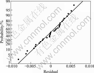
Fig. 1 Normal probability plot of residuals for tool flank wear
The backward elimination process was selected to reduce the insignificant terms. The resulting ANOVA table of the reduced quadratic model for the tool flank wear is presented in Table 6. The reduced model results reveal that this model is still significant in the status of the value of ��Prob.>F�� being 0.05. The other important coefficient R2 in the resulting ANOVA table is defined as the ratio of the explained variation to the total variation and is a measure of the degree of fit. When R2 approaches unity, the response model fits the actual data better. The value of R2 for this reduced model is over 99.45% reasonably close to unity, which is acceptable. The contour plots and surface plots were drawn for various combinations. The numbers present in the contour plot are tool flank wear.
Table 6 Estimated regression coefficients for VBmax after backward elimination

After eliminating the non-significant terms, the final response equation for tool flank wear is given as follows:
VBmax=-0.2577+0.0002X1+2.3189X2+0.0111X3+
0.0119X4+32.3678X22-0.0013X1X2 (6)
From Fig. 2, it is clear that the tool flank wear decreases with the decrease of spindle speed, content of SiCp and feed rate. At a lower spindle speed, tool wear is less, which can be attributed to the formation of larger size unstable built-up-edge (BUE) due to high contact pressure and friction. The formation of unstable larger BUE at a low spindle speed protects the cutting wedge from further wear [19]. But with an increase in spindle speed, an increase in tool wear is observed, which could be due to the generation of higher temperature at higher spindle speed and associated thermal softening and deterioration of form stability of the cutting wedge [20]. Also, the flank wear increases with an increase in feed rate. It is due to BUE formed on flank face that changes the geometry of the tool [21]. Increasing the content of SiCp will increase the tool flank wear. Due to the addition of reinforcing materials which are normally harder and stiffer than the matrix, machining becomes significantly more difficult than in the case for conventional materials [22].
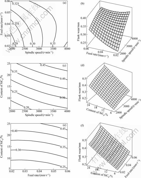
Fig. 2 Response graphs and contour plots: (a) Contour plot of flank wear vs feed rate, spindle speed; (b) Surface plot of flank wear vs feed rate, spindle speed; (c) Contour plot of flank wear vs content of SiCp, spindle speed; (d) Surface plot of flank wear vs content of SiCp, spindle speed; (e) Contour plot of flank wear vs content of SiCp, feed rate; (f) Surface plot of flank wear vs content of SiCp, feed rate
In order to examine the tool wear mechanism in detail, the worn cutting tools were observed using SEM. Sodium hydroxide (1 mol/L) solution was used to remove the work material adhered onto the surface of the tools. Figure 3 shows SEM images of tool at low and high spindle speeds. From Fig. 3(a), it is clear that the flank wear is low at a low spindle speed (2000 r/min). From Fig. 3(b), it is evident that the flank wear is high when the spindle speed is increased to 4000 r/min. This is due to the generation of high contact pressure and temperature between work and tool.
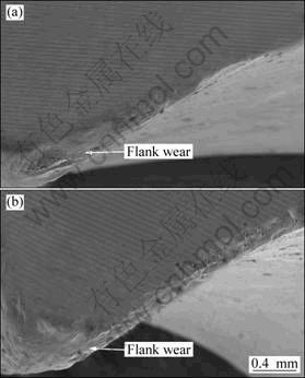
Fig. 3 SEM images of carbide tool: (a) N=2000 r/min, f=0.04 mm/r, d=1.5 mm and S=15%; (b) N=4000 r/min, f=0.04 mm/r, d=1.5 mm and S=15%
4 Optimizing end milling process parameters
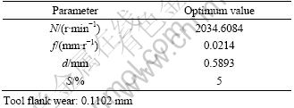
The objective of using response surface methodology (RSM) is not only to investigate the response over the entire factor space, but also to locate the region of interest where the response reaches its optimum or near optimal value. Based on the developed second order response surface equations for correlating the various end milling process parameters with the tool wear values, optimality search can be obtained. An analysis for the optimization of the process parameters has been carried out using RSM optimization technique. Desirability for the whole process optimization has been calculated to show the feasibility of optimization, i.e. to explore whether all the parameters are within their working range or not. The goal is to minimize the tool flank wear. As the composite desirability is close to 1, it can be concluded that the parameters are within their working range. Optimization plot for the response is drawn and a parametric combination is obtained, i.e., spindle speed (N) 2034.6084 r/min, feed rate (f) 0.0214 mm/r, depth of cut (d) 0.5893 mm, and content of silicon carbide (S) 5%. The desirability of optimization has been calculated as 1.0000, namely, all parameters are within their working range. When machining with optimum parametric combination, tool flank wear can be achieved as low as 0.1102 mm. The optimum values of machining process parameters for different machining criteria are presented in Table 7.
Table 7 Optimum values of process parameters considering tool flank wear
In the present study, after determining the optimum conditions and predicting the response under these conditions, a new experiment was designed and conducted with the optimum values of the machining parameters. The results are shown in Table 8. The predicted machining performance was compared with the actual machining performance and a good agreement was obtained between these performances. From the analysis of Table 8, it can be observed that the error is small. The error between the experimental and predicted values for tool wear is 5%. Obviously, this confirms excellent reproducibility of the experimental conclusions.
Table 8 Validation test result

5 Conclusions
1) An empirical relationship was developed to predict the tool flank wear of end milling of LM25 Al/SiCp, by incorporating process parameters. The developed relationship can be effectively used to predict the tool flank wear of carbide end mill cutter at a confidence level of 95%.
2) From the developed model, the optimal process parameter combination, i.e. spindle speed of 2034.6084 r/min, feed rate of 0.0214 mm/r, depth of cut of 0.5893 mm, and content of SiCp of 5% was found out to achieve the minimum tool flank wear as 0.1102 mm.
3) Spindle speed and content of SiCp were found to have greater influence on tool flank wear in end milling of LM25 Al/SiCp MMC, followed by feed rate. Depth of cut has less influence on tool flank wear.
References
[1] BOOTHROYD G, KNIGHT W A. Fundamentals of machining and machine tools [M]. Marcel Dekker, Inc., 1989.
[2] KENNEDY F E, BALBAHADUR A C, LASHMORE D S. The friction and wear of Cu-based silicon carbide particulate metal matrix composites for brake applications [J]. Wear, 1997, 203-204: 715-721.
[3] RAVIKIRAN A, SURAPPA M K. Effect of sliding speed on wear behavior of A356 Al 30wt% SiCp MMC [J]. Wear, 1997, 206: 33-38.
[4] ALLISION J E, GOLE G S. Metal-matrix composites in the automotive industry: Opportunities and challenges [J]. J Min Met Mater Sci, 1993, 45(1): 19-24.
[5] LOONEY L A, MONAGHAM J M, O��REILLY P, TAPLIN D M R. The turning of an Al/SiC metal-matrix composites [J]. Mater Process Technol, 1992, 33(4): 453-468.
[6] CHENNAKESAVARAO B, REDDY P N, KOMARIAH N, MALLA R D. Machinability of vacuum hot pressed metal matrix composites [C]//Proceedings of the Seventeenth AIMTDR Conference. R.E.C. Warangal, 2000: 53-56.
[7] HOCHENG H, YEN Y B, ISHIHARA T, YEN B K. Fundamental turning characteristics of a tribology-favored graphite/aluminum alloy composite material [J]. Compos Part A, 1997, 28: 883-890.
[8] CHAMBERS A R. The machinability of light alloy MMCs [J]. Compos Part A, 1996, 27: 143-147.
[9] YUAN Z J, DONG G S. Ultra precision machining of SiCw/Al composites [J]. CRIP Ann, 1993, 42: 107-109.
[10] EL-GALLAB M, SKLAD M. Machining of Al/SiC particulate metal-matrix composites. Part I: Tool performance [J]. Mater Process Technol, 1998, 83: 151-158.
[11] DAVIM J P. Design of optimization of cutting parameters for turning metal matrix composites based on the orthogonal arrays [J]. Mater Process Technol, 2003, 132: 340-344.
[12] PALANIKUMAR K, KARTHIKEYAN R. Assessment of factors influencing surface roughness on the machining of Al/SiC particulate composites [J]. Mater Des, 2007, 28: 1584-1591.
[13] DABADE U V, JOSHI S S, BALASUBRAMANIAM R, BHANUPRASAD V V. Surface finish and integrity of machined surfaces on Al/SiCp composites [J]. Mater Process Technol, 2007, 192-193: 166-174.
[14] BASHEER A C, DABADE U V, JOSHI S S. Modeling of surface roughness in precision machining of metal matrix composites using ANN [J]. Mater Process Technol, 2008, 197: 439-444.
[15] PENDSE D M, JOSHI S S. Modeling and optimization of machining process in discontinuously reinforced aluminium matrix composites [J]. Mach Sci Technol, 2004, 8: 85-102.
[16] PALANIKUMAR K, DAVIM J P. Assessment of some factors influencing tool wear on the machining of glass fibre-reinforced plastics by coated cemented carbide tools [J]. Mater Process Technol, 2009, 209: 511-519.
[17] MURTI K G, SUNDERESAN S. Structure and properties of friction welds between high-speed steel and medium carbon steel for bimetal tools [J]. Mater Sci Technol, 1986, 2: 865-870.
[18] KUMAR S, KUMAR P, SHAN H S. Effect of evaporative pattern casting process parameters on the surface roughness of Al�C7% Si alloy castings [J]. Mater Process Technol, 2007, 182: 615�C623.
[19] MASOUNAVE J, LITWIN J, HAMELIN D. Prediction of tool life in turning aluminum matrix composites [J]. Mater Des, 1994, 15: 287-293.
[20] KILICKAP E, AKSOY M, INAN A. Study of tool wear and surface roughness in machining of homogenized SiCp reinforced aluminum metal matrix composite [J]. Mater Process Technol, 2005, 164-165: 862-867.
[21] HUNG N P, BOEY F Y C, KHOR K A, PHUA Y S, LEE H F. Machinability of aluminum alloys reinforced with silicon carbide particulates [J]. Mater Process Technol, 1996, 56: 966-977.
[22] QUAN Y, ZEHUA Z. Tool wear and its mechanism for cutting SiC particle-reinforced aluminium matrix composites [J]. Mater Process Technol, 2000, 100: 194-199.
�������ϲ���ϳ���ӹ����̲�����Ԥ�����Ż�
R. AROKIADASS, K. PALANIRADJA, N. ALAGUMOORTHI
Department of Mechanical Engineering, Pondicherry Engineering College, Puducherry-605 014, India
ժ Ҫ���о���LM25Al/SiCp���ϲ��ϵ�ϳ���ӹ�����������õ�����������ݲ�����Ӧ�淽��������һ����ѧģ�����������ּӹ������Ժ���ĥ���ʵ�Ӱ�졣���ñ�����Ӧ�淽�������ʵ�顣������������������ʵ���о���Χ�ڣ�����������ѧģ���ܹ��ܺõ�����ϳ���ӹ���������Ӱ�졣�����Ż���ϲ����õ�����С�ĺ���ĥ���ʡ�
�ؼ��ʣ�ϳ���ӹ������������ϲ��ϣ���Ӧ�淽�����Ż�
(Edited by YUAN Sai-qian)
Corresponding author: R. AROKIADASS; Tel: +91-9791488706; E-mail: raja_arokiadass@yahoo.com
DOI: 10.1016/S1003-6326(11)61357-5

