Design and simulation of electrical dynamometer using improved DTC induction motor driver
��Դ�ڿ������ϴ�ѧѧ��(Ӣ�İ�)2017���6��
�������ߣ������ ������ ������
����ҳ�룺1360 - 1368
Key words��dynamometer; induction motor; direct torque control (DTC); direct torque control method-space vector modulation DTC-SVM; PI controller
Abstract: AC motors, especially the squirrel cage induction motors have the advantages of simple structure, good reliability and low cost. They are more suitable to be used as electrical dynamometers to provide dynamic load for bench test systems. But, the speed and torque of induction motors are not easy to be controlled accurately. In this work, an electrical dynamometer based on the induction motor is proposed. In order to get better control performance of torque and speed of induction motor, an improved direct torque control method (DTC) is also developed based on the space vector modulation (SVM) technique. The performance of the proposed dynamometer system is validated in the Matlab/Simulink platform. The simulation results show that the new dynamometer has good torque and stator flux response. And the torque and stator current ripples of it are reduced significantly compared with using the conventional DTC method.
Cite this article as: ZHU Cheng-li, WANG Yan-zhong, HOU Liang-wei. Design and simulation of electrical dynamometer using improved DTC induction motor driver [J]. Journal of Central South University, 2017, 24(6): 1360-1368. DOI: 10.1007/s11771-017-3540-7.
J. Cent. South Univ. (2017) 24: 1360-1368
DOI: 10.1007/s11771-017-3540-7

ZHU Cheng-li(�����), WANG Yan-zhong(������), HOU Liang-wei(������)
School of Mechanical Engineering and Automation, Beihang University, Beijing 100191, China
 Central South University Press and Springer-Verlag Berlin Heidelberg 2017
Abstract: AC motors, especially the squirrel cage induction motors have the advantages of simple structure, good reliability and low cost. They are more suitable to be used as electrical dynamometers to provide dynamic load for bench test systems. But, the speed and torque of induction motors are not easy to be controlled accurately. In this work, an electrical dynamometer based on the induction motor is proposed. In order to get better control performance of torque and speed of induction motor, an improved direct torque control method (DTC) is also developed based on the space vector modulation (SVM) technique. The performance of the proposed dynamometer system is validated in the Matlab/Simulink platform. The simulation results show that the new dynamometer has good torque and stator flux response. And the torque and stator current ripples of it are reduced significantly compared with using the conventional DTC method.
Key words: dynamometer; induction motor; direct torque control (DTC); direct torque control method-space vector modulation DTC-SVM; PI controller
1 Introduction
Dynamometer is the most important part of a bench test system. It is not only used to measure the power and torque applied on the under test machines, but also is used to provide simulated dynamic load for them [1-3]. Several kinds of dynamometers have been developed in the past decades. They are water brake dynamometer, eddy current dynamometer, powder dynamometer, hysteresis dynamometer and electrical dynamometer. The first four belong to the power absorption dynamometer, and the last one belongs to power transfer dynamometer. The power absorption dynamometers absorb mechanical energy and make it become heat and dissipated directly. Except for the water brake dynamometer, the other kinds of power absorption dynamometers cannot be used with high power capability, due to their low rates of heat dissipation. Otherwise, their body temperature will become very high. This will affect the accuracy and stability of the dynamometer, even cause the dynamometer burning out [4, 5]. Additionally, the power absorption dynamometers make a great waste of energy. They are not environment friendly, especially in long- time running cases. So, they are going to be replaced by the power transfer dynamometers. Electrical dynamometers belong to power transfer dynamometers; they make the electrical motors run in generator mode to absorb mechanical energy and transfer them to electrical energy. And the power generated by electrical dynamometers can be re-used or returned to the power grid. This can bring significant reduction of energy consumption. At the same time, electrical dynamometers have the advantages of high power capacity, low heat generation, high accuracy, stable performance and long lifetime. They are increasingly becoming the focus of research in this field [6].
Since DC motors have good starting-up, wide speed range, smooth speed regulation, and easy to be controlled, they are early used as electrical dynamometer [7]. In Ref. [8], a permanent magnet DC machine has been used as dynamometer to emulate the mechanical loads. NEWTON et al [9] developed an electrical dynamometer with a DC machine to simulate both the static and dynamic characteristics of a representative industrial load. The nonlinear effects in real loads can be accurately simulated by the DC machine which worked under a control strategy based on local vector control. However, DC motors have mechanical commutators and brushes. They make the maintenance of DC motors relatively difficult [10]. Moreover, DC motors have disadvantages of big size, high cost and short lifetime. And the power capacity, speed and voltage of single DC motor are limited. On the contrary, the AC motors, especially the squirrel cage induction motors, have the characteristics of simple structure, good reliability and low costs. They also can be used in harsh environments. But, an AC motor is a multi-variable, nonlinear, and strong coupling system and its speed and torque are not easy to be controlled accurately [11]. Several control approaches, such as scalar based control method, field oriented control (FOC) [12] method, vector control method,direct torque control (DTC) method [13], and some DTC variants methods [14, 15], have been developed to improve the control performance of AC motors [16]. This makes the AC induction motors have been successfully used in electrical dynamometers. A dynamometer system with a permanent magnet synchronous machine (PMSM) which was driven by voltage source inverter using IGBT's was presented in Ref. [17]. Vector-controlled induction machine dynamometers have been presented in Refs. [18, 19]. A dynamometer using induction motors controlled by field orientation control technique was presented in Ref. [20]. In the FOC method, the motor equations are transformed into a rotating coordinate system which is synchronized with the rotor flux. The FOC method can ensure that torque and flux decoupling in spite of equations of induction motor are nonlinear. However, The FOC technique is complex and difficult to be implemented, since it needs reference frame transformation and the performance of it depends on the mechanical speed and motor parameters [21]. The DTC method has the advantages of high performance, fast dynamic response, and robustness to the variation of the machine parameters. And also, it doesn��t need current controller and coordinate transformation. At the same time, this method is relatively easy to be implemented using computer technology. So, the DTC control strategy is becoming more and more popular in recent years. But the main problem of the conventional DTC method is torque ripple and varying inverter switch frequency [22].
In this work, an electrical dynamometer based on the induction motor is proposed. In order to get better torque and speed control performance, an improved DTC control method is also developed based on the space vector modulation (SVM) technique [23]. The improved DTC control strategy has the constant switching frequency. And the performance of the proposed dynamometer is evaluated in the Matlab/Simulink platform.
2 Induction motor model and improved DTC control method
2.1 Induction motor mathematical model
The dynamic model of three-phase induction motor can be expressed by mathematical equations in stationary reference frame. The stator voltage vector equations of induction motor can be written as

where Us is stator voltage space vector; Is is stator current space vector; Rs is the resistant of the stator coil; and ��s is the stator flux linkage space vector.
In ���� frame, the stator voltage vector components of the induction motor can be expressed as

The stator flux vector ��s and ���� components equations in the stationary reference frame can be written as:


where Ls is the stator self-inductance; Lm is the mutual inductance between stator and rotor; Ir is the rotor current.
Similarly, the rotor flux vector ��r and ��, �� components equations in the stationary reference frame can be expressed as


where Lr is the rotor self-inductance.
The electromagnetic torque Te produced by the induction motor in terms of stator flux and stator current vectors can be expressed as follows.

where pn is the number of pole pairs.
The relationship among stator current, stator flux and rotor flux can be written as


Submiting Eq. into Eq. , the electromagnetic torque Te can be expressed as


where �� is the angle between the stator and rotor flux vectors, i.e. the torque angle. The torque balance equation of the dynamic rotor rotation can be written by

where �� is the angular speed of the rotor; TL is the load torque; B is the viscous constant; and J is the inertia of the induction motor.
From Eq. , it can be seen that the electromagnetic torque is the cross vector product between stator and rotor flux vectors. If the sample time is short enough, the amplitude of the stator flux is generally kept constant at the reference value. Accordingly, the rotor flux is also kept constant because it changes slower than the stator flux. The electromagnetic torque can be controlled by changing the torque angle ��. And the angle �� can be easily controlled by choosing appropriate stator voltage space vectors.
2.2 Conventional DTC method
The conventional DTC control method for the induction motor was proposed by TAKAHASHI and NOGUCHI [24] in the middle of 1980s. The block diagram of the conventional DTC system for induction motor is shown in Fig. 1. The basic DTC scheme includes five major components: flux and torque comparators, switching table, voltage source inverter (VSI), flux and torque estimators and induction machine. Unlike FOC control system, it is simple and has no inner current regulation loop. And it doesn��t need complicated coordination transformations. Additionally, the problem of decoupling the stator current in the FOC control system is avoided. The basic principle of DTC control method is that the stator voltage vectors (inverter switch status) are directly selected according to the errors between the reference and the detected values of torque and stator flux linkage. The stator flux and electromagnetic torque are controlled by corresponding hysteresis comparators. The outputs of the comparators and the position of the stator flux are fed to the switching table to select an appropriate inverter voltage vector which will be applied on the induction machine.
The VSI (voltage source inverter) is used to convert DC power to three-phase AC power. The three-phase VSI consists of six active switches (IGBT transistors or GTO thyristors). But only one switch can be turned on at any one time in an inverter-leg. This can avoid short- circuiting in the DC power. In the three-phase VSI, there are eight voltage vectors corresponding to eight possible switch states. Among those voltage vectors, there are six active vectors which have the same amplitude and two zero vectors.
The inverter can generate any output voltage in average under the control of a suitable modulation method, and of course the output voltage is limited by the DC voltage. In order to get suitable output voltage, the pulse width modulation (PWM) methods [25] were developed in recent years. And the general idea of PWM method is based on a sequential switching of active and zero vectors. In the conventional DTC method, only one voltage vector is applied in a sampling period. In order to reduce the torque ripple, it is used more than one vector within a sampling period. Thus, the slip frequency can be controlled precisely by inserting zero vectors. This requires switching frequency changing according to the width of hysteresis band. And, the operation frequency of PWM inverter is very high when the hysteresis band is relatively small.
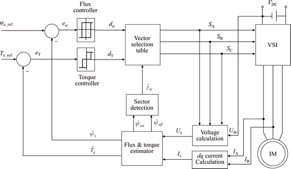
Fig. 1 Block diagram of conventional DTC method
The conventional DTC control method can provide a very quick and precise torque response for the induction machine without the need of complex field orientation blocks and inner current regulation loops. It also has the simple structure and is relatively easy to be realized. But it has some common disadvantages: serious torque ripple and varying inverter switch frequency.
2.3 Improved DTC control method
In order to overcome the drawbacks of the conventional DTC control method, an improved DTC control method based on the space vector modulation (SVM) technique is developed for the induction machine to reduce the torque ripple of the electrical dynamometer. This kind of induction motor control method is named DTC-SVM method. The basic concept of SVM is adjusting the flux speed by inserting zero voltage vectors to control the induction machine��s electromagnetic torque. The switching signals of the inverter in the DTC-SVM method are generated by the space vector modulator based on the average values. But the control signals of the inverter in the conventional DTC method are directly calculated based on the instantaneous values. This is the main difference between the conventional DTC control method and the DTC-SVM control method. In the DTC-SVM control method, the inverter has a constant switching frequency, and the torque ripple is significantly reduced using similar hardware topology like that in the conventional DTC method.
In the proposed DTC-SVM scheme, both torque and flux magnitudes are controlled with closed-loop way. They are regulated by the PI controllers respectively. This kind of DTC-SVM method provides further improvement for classical DTC scheme. So, it is used as the control strategy for our electrical dynamometer. The block diagram of the proposed DTC-SVM schema for a voltage source inverter fed induction machine is presented in Fig. 2.
The proposed DTC-SVM schema is based on the information of flux, torque and mechanical speed. For purpose of reducing number of sensors, getting more reliable operation and reducing costs, some estimation algorithms are used to get state variables and the required feedback signals. In this work, the magnitude of the stator flux reference is considered constant. As shown in Fig. 3, the reference stator flux vector can be calculated by

The components of the stator flux reference in the stationary coordinate system can be written as follows:


The stator flux estimation can be derived from the voltage flux-current equations of the induction motor Eq. . It can be written as

As described in Eq. , the stator flux vector estimation is calculated by integrating the motor back electromagnetic force (EMF). However, it is difficult to be implemented associated with a pure integrator, because of the DC drift and initial value problems. In this work, an estimator based on voltage model with reference flux is used to overcome this problem. The basic of this estimator is that the rotor and the stator flux vector are calculated based on the stator voltages and currents. Moreover, the difference between the reference and estimated rotor flux magnitude is used to correct the estimated values. The rotor flux is calculated as

where k is the gain factor; Er is the rotor back EMF, which is defined as

From Eq. , the reference stator flux can be described as

This flux estimator has a good dynamic performance. Additionally, the rotor flux can be obtained by this algorithm, which is necessary for rotor speed calculation. With the stator flux components  and
and  , the angle of the stator flux can be obtained by

With Eq. , the electromagnetic torque of the induction motor in the stationary coordinate system can be calculated as follows:

It is clear that the estimated electromagnetic torque depends on the measurement accuracy of the current and flux estimation.
From Fig. 2, it can be seen that the inputs of the voltage calculation block are the DC power voltage and the inverter switch states (SA, SB, SC). The stator voltage vector can be expressed as

As shown in Fig. 2, the error between the estimated stator flux and reference stator flux is the input signal of the PI controller. It is used to calculate the stator voltage component Usd_ref, which can be described as

where kp is controller gain; Ti is controller integrating time.
Similarly, the estimated electromagnetic torque is compared with the reference electromagnetic torque to generate the error signal for the torque PI controller. And the output of the torque PI controller is the stator voltage vector component Usq_ref, which can be written as

where kp is controller gain; Ti is controller integrating time.
The reference stator voltage vector components Usd_ref and Usq_ref are transformed into stationary reference frame (���� frame) by the coordinate transformation functions. Then, the DC voltage commands are forwarded to the SVM block which can perform the space vector modulation. After that, appropriate space voltage vector can be generated by the three-phase inverter with the inverter switch PWM signals (SA, SB, SC) calculated by the SVM block.
Comparing with the conventional DTC system, the hysteresis controllers are replaced by the PI controllers, and the switching table is replaced by the space vector modulator (SVM) in the proposed DTC-SVM drive system. The error vector in flux and torque can be fully compensated. As a result, the torque and flux are directly controlled in closed loops, and therefore the DTC�CSVM will operate at a constant switching frequency to reduce torque and flux ripples.
3 Structure of proposed electrical dynamometer
Actually, most of the desired linear and nonlinear load can be expressed as

where T0 is the constant load torque; B is the viscous friction constant; J is the inertia; C2 is the parameter for quadratic speed-dependent load; C3 is the parameter for cubic speed-dependent load; �� is the angular speed.
The required dynamic load can be realized by varying these parameter values. For example, the static load can be got when B, C2, C3 and J are set zero; linear load can be realized when C2 and C3 are set zero; and nonlinear load can be realized when C2 or C3 is not zero.
It is assumed that the machine under test is rigidly coupled with the dynamometer. The mechanical equation of the dynamometer system can be written as

where TLe is the electromagnetic torque of the dynamometer; JL is the inertia of the dynamometer; BL is the viscous friction of the dynamometer; ��L is the dynamometer angular speed.
Considering the driving machine and the dynamometer are rigid coupled, their speeds are strictly equal:


Substituting Eqs. , and into Eq. , the electromagnetic torque of the dynamometer can be written as

From Eq. we can see that the reference electromagnetic torque of the dynamometer is calculated from the preset parameters, T0, B, BL, C2, C3, J and JL.
In the proposed electrical dynamometer, the induction motor controlled by the DTC-SVM method is used to produce the desired dynamic load for the test system. The block diagram of the control strategy for the proposed dynamometer is illustrated in Fig. 4.
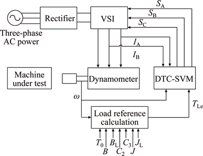
Fig. 4 Block diagram of control strategy for proposed dynamometer
From Fig. 4 we can see that the reference electro- magnetic torque is calculated from Eq. according to the angular speed of the dynamometer and the preset parameters. Then, the reference electromagnetic torque and the angular speed are sent to the DTC-SVM control bock to generate the inverter switch state signals. The output mechanical torque is applied on the under test machine. In the proposed dynamometer, the electromagnetic torque and stator flux are regulated by close loop method. Because it does not need torque sensor, the torque response is very fast.
4 Simulation and results
In order to verify the performance of the proposed dynamometer and its control method in steady and dynamic states, the simulation model is built and simulated in Matlab/Simulink platform. In this work, the dynamometer machine is actually a three-phase induction motor with corresponding drive. Two simulation models are developed to examine the control methods. One is for the DTC-SVM method, and the other is for conventional DTC method. The machine under test (drive machine) is a single-phase dual-converter DC motor. The DC motor is rated 2.2 kW, 240 V and 1800 r/min. It is speed controlled. While, the dynamometer is torque controlled. The inputs to the dynamometer are the parameters which are used to calculate the desired torque to be emulated, and the input to the under test machine is essentially a speed reference. The couplings connecting the motors and the torque transducer are assumed to be rigid. The simulation model of the dynamometer system is shown in Fig. 5.
As shown in Fig. 5, the simulation model includes DC drive motor, AC dynamometer (AC motor controlled by the DTC-SVM method), shaft, power modules, and some measurement modules. The AC dynamometer provides dynamic load for the DC motor which is used to act as under test machine. The torque is transferred between the DC motor and the dynamometer through a rigid shaft. The stator currents, rotor speed, electromagnetic torque, and the stator flux of the DC motor and the AC dynamometer are measured by the measurement modules and are shown on the scope.
As for the dynamometer drive system, the switching frequency of SVM is 4.5 kHz. And the stator flux reference is considered 0.5 Wb which is the rated stator flux.
Before the dynamometer is used to emulate the load applied on under the test machine, we studied its speed response with no load under the control of conventional DTC method and the proposed DTC-SVM method, respectively. The speed reference is set 500 r/min at start time. The speed responses are shown in Figs. 6 and 7.
From Figs. 6 and 7 we can see that it used about 0.28 s to reach the reference speed, 500 r/min. The rise time has no significant difference under two kinds of control methods. But the overshoot under the control of DTC-SVM is a little bigger than that of conventional DTC. This is caused by the PI regulators used in the torque and flux closed control loops in DTC-SVM control method.
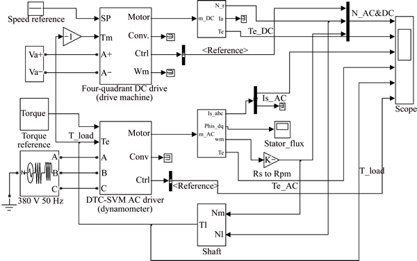
Fig. 5 Simulation model for proposed electrical dynamometer
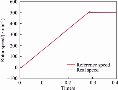
Fig. 6 Speed response with no load by DTC-SVM method
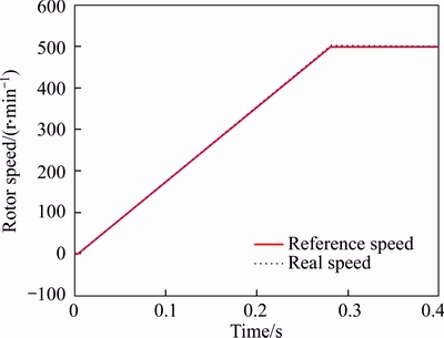
Fig. 7 Speed response with no load by conventional DTC method
During the load emulating simulation process, the speed reference for the drive DC motor is set 500 r/min, and the torque reference input to the dynamometer is set 10 N��m at start time. After 0.8 s, the torque reference of the dynamometer is changed to 0 N��m, and at 1.2 s, the torque is changed to -10 N��m. Induction motor parameters are 3-phase, 50 Hz, 220/380 V, Nr=1435 r/min, J=0.089 kg/m2, 2.2 kW, 4-pole, 1.8/1.05 A, Lm=0.0693 H, friction=0.005, Rs=0.435 ��, Rr=0.816 ��, Ls=0.002 H, Lr=0.002 H.
The compared electromagnetic torques of the dynamometer under the control of conventional DTC control method and proposed DTC-SVM control method are shown in Figs. 8 and 9. As shown in the comparing figures, the electromagnetic torque variation of the dynamometer under the DTC-SVM control method and conventional DTC control method is in accordance with the torque reference variation. It is obvious that the torque ripple of the DTC-SVM scheme is about half of the conventional DTC method in the steady state. The torque ripple of the dynamometer is reduced significantly under the control of proposed DTC-SVM method compared with that of the conventional DTC method.
The stator currents (phase A) in response to the torque change under the two control methods are presented in Figs. 10 and 11. It can be seen that the current magnitudes change with the torque variation. The waveforms obtained using both of the two control methods are similar sinusoidal wave. In the start-up stage, the phase currents are like to be suffering a little distortion. It can be seen that the current waveform in Fig. 10 is much better than the waveform shown in Fig. 11.
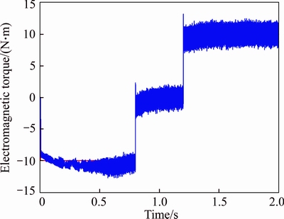
Fig. 8 Electromagnetic torque response by DTC-SVM method
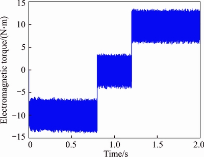
Fig. 9 Electromagnetic torque response by conventional DTC method
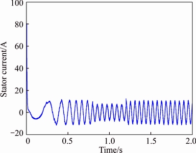
Fig. 10 Stator current by DTC-SVM method
The stator actual flux locus of the dynamometer in dq plane under the DTC-SVM method and conventional DTC method are shown in Figs. 12 and 13, respectively. It is to be noted that the flux locus of the DTC-SVM method is much smoother and circular; this is due to the accuracy of flux control loop in it.
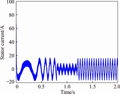
Fig. 11 Stator current by conventional DTC method
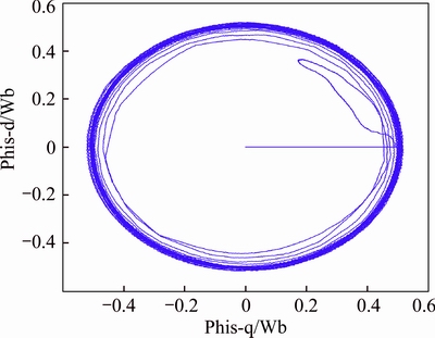
Fig.12 Stator flux by DTC-SVM method
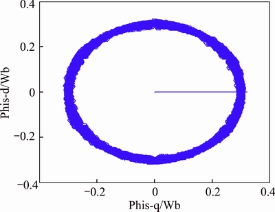
Fig.13 Stator flux by conventional DTC method
5 Conclusions
An electrical dynamometer based on the induction motor is proposed. In order to get better torque and speed control performance, an improved DTC control method is developed based on the space vector modulation technique. In the improved DTC control method, the hysteresis controllers are replaced by the PI controllers. And the voltage space vector control technique is used in this control method to make the inverter operate a constant switching frequency. In the proposed dynamometer, the electromagnetic torque and stator flux are regulated by close-loop controllers.
The performance of the proposed dynamometer is verified in the Matlab/Simulink platform. The simulation results show that the dynamometer has good torque and stator flux response, and the ripples of the torque and stator current are reduced significantly compared with the convention DTC control method.
References
[1] GUAN Qiang, DU Dan-feng. Research on present status of small engine dynamometers [J]. Forest Engineering, 2006, 22(4): 24-25. (in Chinese)
[2] AKPOLAT Z H, ASHER G M, ARELLANO-PADILLA J. A test bed for the experimental validation of position control algorithms [J]. Control engineering Practice, 2004, 12(8): 933-943.
[3] KYSLAN K,  F. Control of a test bench for dynamic emulation of mechanical loads [J]. Procedia Engineering, 2012, 48(1): 352-357.
[4] CHALMERS B J, DUKES B J. High-performance eddy-current dynamometers [J]. Electric Power Applications IEE Proceedings B, 1980, 127(1): 20-28.
[5] ZHANG Zhen-hai, CHI Chang-chun, LIU Jiao-jiao, LIAN Zheng-bing, SHAO Shi-liang. The motor temperature rise test system based on magnetic powder dynamometer [J]. Advanced Materials Research, 2014, 998-999: 495-498.
[6] TOPOLNICKI J, SKOCZYLAS N. Low cost high sensitivity dynamometer [J]. Measurement, 2011, 44(1): 74-79.
[7] MORALES R, SOMOLINOS J A, SIRA-RAMIREZ H. Control of a DC motor using algebraic derivative estimation with real time experiments [J]. Measurement, 2014, 47: 401-417.
[8] KYSLAN K, KUSNIR E, FEDAK V, LACKO M. Dynamic emulation of mechanical loads with backlash based on rapid control prototyping [C]// Power Electronics and Motion Control Conference and Exposition (PEMC), 2014, 16th International. IEEE, 2014: 1209-1215.
[9] NEWTON R W, BETZ R E, PENFOLD H B. Emulating dynamic load characteristics using a dynamic dynamometer [C]// Power Electronics and Drive Systems, Proceedings of 1995 International Conference on. Singapore: IEEE, 1995: 465-470.
[10] KARTHIKEYAN J, SEKARAN R D. Current control of brushless dc motor based on a common dc signal for space operated vehicles [J]. International Journal of Electrical Power & Energy Systems, 2011, 33(10): 1721-1727.
[11] HUANG K S, KENT W, WU Q H, TURNER D R. Parameter identification for foc induction motors using genetic algorithms with improved mathematical model [J]. Electric Power Components & Systems, 2001, 29(3): 247-258.
[12] GABRIEL R, LEONHARD W, NORDBY C J. Field-oriented control of a standard AC motor using microprocessors [J]. IEEE Transactions on Industry Applications, 1980, 16(2): 186-192.
[13] CASADEI D, SERRA G, TANI A, ZARRI L. Assessment of direct torque control for induction motor drives [J]. Bulletin of the Polish Academy of Sciences Technical Sciences, 2006, 54(3): 237-254.
[14] LI Xun, LIU Wu-ling, GUI Wei-hua, YU Shou-yi. A novel flux weakening scheme for direct torque control system of induction motor based on maximal torque control [J]. Journal of Central South University: Science and Technology, 2012, 43(1): 177-183. (in Chinese)
[15] BUJA G S, KAZMIERKOWSKI M P. Direct torque control of PWM inverter-fed AC motors-a survey [J]. IEEE Transactions on Industrial Electronics, 2004, 51(4): 744-757.
[16] SUTIKNO T, IDRIS N R N, JIDIN A. A review of direct torque control of induction motors for sustainable reliability and energy efficient drives [J]. Renewable & Sustainable Energy Reviews, 2014, 32(5): 548-558.
[17] SANDHOLDT P, RITCHIE E, PEDERSEN J K, BETZ R E. A dynamometer performing dynamical emulation of loads with nonlinear friction [C]// Industrial Electronics. ISIE'96, Proceedings of the IEEE International Symposium on. Warsaw: IEEE, 1996, 2: 873-878.
[18] ARELLANO-PADILLA J, ASHER G M, SUMNER M. Control of an AC dynamometer for dynamic emulation of mechanical loads with stiff and flexible shafts [J]. IEEE Transactions on Industrial Electronics, 2006, 53(4): 1250-1260.
[19] AKPOLAT Z H, ASHER G M, CLARE J C. Dynamic emulation of mechanical loads using a vector-controlled induction motor-generator set [J]. IEEE Transactions on Industrial Electronics, 1999, 46(2): 370-379.
[20] HASSANIA B, SICARD P, BA-RAZZOUK A. Solutions to typical motor load emulation control problems [C]// Electrimacs. OMEGAt: Pierre Mercier, 2002.
[21] REZA C M F S, ISLAM M D, MEKHILEF S. A review of reliable and energy efficient direct torque controlled induction motor drives [J]. Renewable & Sustainable Energy Reviews, 2014, 37(3): 919-932.
[22] KUMSUWAN Y, PREMRUDEEPREECHACHARN S, TOLIYAT H A. Modified direct torque control method for induction motor drives based on amplitude and angle control of stator flux [J]. Electric Power Systems Research, 2008, 78(10): 1712-1718.
[23] AZCUE-PUMA J L, GAZIOLLA H, SGUAREZI F A J, RUPPERT E. A modified load angle based DTC-SVM scheme for three-phase induction motors [J]. Przeglad Elektrotechniczny, 2013, 89: 309-313.
[24] TAKAHASHI I, NOGUCHI T. A new quick-response and high-efficiency control strategy of an induction motor [J]. IEEE Transactions on Industry Applications, 1986, 22(5): 820-827.
[25] HOLMES D G, LIPO T A. Pulse width modulation for power converters [M]. Wiley & Sons, 2003.
(Edited by YANG Hua)
Cite this article as: ZHU Cheng-li, WANG Yan-zhong, HOU Liang-wei. Design and simulation of electrical dynamometer using improved DTC induction motor driver [J]. Journal of Central South University, 2017, 24(6): 1360-1368. DOI: 10.1007/s11771-017-3540-7.
Foundation item: Project(SS2012AA04104) supported by High-tech Research and Development Program of China
Received date: 2015-11-23; Accepted date: 2016-03-17
Corresponding author: ZHU Cheng-li, Doctoral Candidate; Tel: +86-13552368002; E-mail: chenglizhu888@163.com

