J. Cent. South Univ. Technol. (2007)01-0135-05
DOI: 10.1007/s11771-007-0027-y

Dynamic analysis and modal test of long-span cable-stayed bridge based on ambient excitation
CHEN Chang-song(陈常松)1,2, YAN Dong-huang(颜东煌)1
(1. School of Bridge and Structure Engineering, Changsha University of Science and Technology,Changsha 410076, China;
2. School of Civil and Architectural Engineering, Central South University, Changsha 410083, China)
Abstract: To study the stiffness distribution of girder and the method to identify modal parameters of cable-stayed bridge, a simplified dynamical finite element method model named three beams model was established for the girder with double ribs. Based on the simplified model four stiffness formulae were deduced according to Hamilton principle. These formulae reflect well the contribution of the flexural, shearing, free torsion and restricted torsion deformation, respectively. An identification method about modal parameters was put forward by combining method of peak value and power spectral density according to modal test under ambient excitation. The dynamic finite element method analysis and modal test were carried out in a long-span concrete cable-stayed bridge. The results show that the errors of frequencies between theoretical analysis and test results are less than 10% mostly, and the most important modal parameters for cable-stayed bridge are determined to be the longitudinal floating mode, the first vertical flexural mode and the first torsional mode, which demonstrate that the method of stiffness distribution for three beams model is accurate and method to identify modal parameters is effective under ambient excitation modal test.
Key words: bridge engineering; cable-stayed bridge; dynamic finite element method; ambient excitation; modal test
1 Introduction
It is one of the very promising areas to study dynamical finite element method(FEM) and carry out modal test based on ambient excitation about long-span cable-stayed bridge[1-5]. As to dynamical FEM model of cable-stayed bridge, there are several different models, such as fish bone model, double beams model and three beams model etc. Because the first two models cannot fully describe the distribution of stiffness and mass for main girder, LI[6] analyzed the distribution of mass and stiffness of three beams model on the assumption of rigid cross section, but the conclusions may be completely different if actual stiffness is considered for diverse cross sections. The conventional modal test methods have been applied extensively in many areas such as aviation, aerospace, navigation and automobile, but most of these methods generally need artificial excitation in the test, and cannot meet the demand of engineering structures[7-8]. Recently, it is very prospective to identify the modal parameters directly using vibration response under ambient excitation in various research fields[9-11]. In the present study, the dynamic mechanical behavior of the cable-stayed bridge, named Jingzhou Yangtze River Bridge was taken as an example to investigate the stiffness distribution method for FEM dynamical model of three beams and technique of modal test.
2 Distribution of dynamic stiffness of double
ribs girder
The distribution of mass and dynamic stiffness of three beams can be deduced by Hamilton principle. If a girder with double ribs is divided into three parallel beams, then the total kinetic energy and potential energy produced by loth beams should be equal to those of the original single girder.
Because of flexural and torsional vibration of beam, cable and tower, the kinetic energy T is made up of two parts: energy T1 due to parallel movement and energy T2 due to rotation. Then the kinetic energy of every element of FEM model is given by
 ,
, ,
, (1)
(1)
where m represents the mass of element, vc is the vibrational velocity of centroid of cross section, Jc and ωr denote rotational inertia and circumferential velocity of rotation, respectively.
The potential energy (V) of element can be obtained by
V=Vb+Vo+Vs+VH+VB (2)
where Vb is the strain energy due to flexural deformation, Vo is the strain energy due to axial deformation, Vs is the strain energy due to shearing deformation, VH is the strain energy of free torsional deformation, VB is the strain energy of the restricted torsional deformation. The following equations can be obtained:

where u, v and w are the translation displacements in the directions x, y and z of local coordination system, respectively; θx, θy and θz are the rotational angles along directions x, y and z, respectively; Iy, Iz, Jd and Jω are the moments of inertia of flexural along directions y and z, free torsional and restricted torsional deformation, respectively; k is the numerical factor to correct the shearing strain; A and N represent the cross area and axial forces of beam, respectively. Usually, the three beams are made of the same material, then their elastic modulus and shearing modulus are denoted by E and G, respectively.
2.1 Distribution of mass and polar moment of inertia
As shown in Fig.1, the girder with double ribs has cross area of A and mass of m. When it is simplified into three beams model, the area and mass of beam 1 are A1 and m1, respectively. Beam 2 has area of A2 and mass of m2. Because the three beams have equal velocity of translation when considering the flexural vibration, if
m1+2m2=m, A1+2A2=A (3)
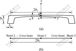
Fig.1 Schematic diagram of girder with double ribs(a) and three beams model(b)
then, the sum of kinetic energy of the simplified model should be equal to that of the original girder. When the torsional vibration is taken into account, in order to guarantee the rotational kinetic energy of the simplified model to equal that of the original girder, the following equations should be satisfied:
Jc1+2Jc2=Jc,  (4)
(4)
where Jc, Jc1 and Jc2 are the rotational inertia of the original girder, beam 1 and beam 2, respectively; Ix, Ix1 and Ix2 are polar moments of inertia of original girder, beam 1 and beam 2, respectively; b1 denotes the distance between beam 1 and beam 2.
2.2 Distribution of vertical flexural stiffness
When the girder vibrates due to the flexural deformation on the vertical plane, the three beams will have the same vertical translation displacement w. If the simplified model has equal vertical flexural strain energy with original girder, then following expression should be satisfied:
Iy1+2Iy2=Iy (5)
where Iy, Iy1 and Iy2 are the bending moments of inertia in the direction y of the original girder, beam 1 and beam 2, respectively.
2.3 Distribution of horizontal flexural stiffness
Since the three beams are jointed by many transverse rigid beams, they have the same horizontal translation displacement when the horizontal flexural vibration takes place. If the horizontal flexural strain energy of the simplified model is equal to that of original girder, the following equation should be erected:
Iz1+2Iz2=Iz (6)
where Iz, Iz1 and Iz2 are the bending movements of inertia in the direction z of the original girder, beam 1 and beam 2, respectively.
2.4 Distribution of shearing stiffness
If the transverse beams are analyzed with real rigidity which can be calculated by effective width of plate, the shearing strain energy of the simplified model and original girder should be equal when Eqn.(6) is satisfied due to the vibration on horizontal plane.
2.5 Distribution of free torsional stiffness
The torsional stiffness mainly affects the torsional frequency and the modes of vibration for cable-stayed bridge. The torsional frequency is very important to calculate the critical velocity of wind. Because the girder with double ribs is not a closed section, the following relation can be deduced by use of film simulation theory:
Jd1+2Jd2=Jd (7)
where Jd, Jd1 and Jd2 are the torsional moments of inertia for the original girder, beam 1 and beam 2, respectively.
In addition, free torsional deformation (?θ/?x) of the three beams in simplified model are equal because the three beams are jointed by the transverse beam. If Eqn.(7) is satisfied, the strain energy of the free torsional deformation of the simplified model and original girder will be equal.
2.6 Distribution of restricted torsional stiffness
2.6.1 Restricted rotational moment of inertia for double- ribs girder
Because the torsional deformation of two ribs is restricted by the transverse beams, the restricted rotational moment of inertia can be calculated in terms of the open cross section assumption. As shown in Fig.2, the centroid of original girder is denoted by c, the direction z (to be neglected in figure) is the symetrical axis, the point d is the torsional centroid of cross section, and e is the intersection of the girder middle plane. If e represents the polar point and zero point of fan coordinate, then the following relation can be obtained:
Jω=Jωe+azJzωe (8)
where Jω represents the restricted rotational moment of inertia, and following equations can be obtained:
 ,
, ,
,
Based on theory of thin wall structural mechanics[6], there exists:
 (9)
(9)
2.6.2 Restricted rotational moment of inertia for three beams model
As shown in Fig.2, beam 2 will deform flexurally when the torsional deformation of girder takes place wholly. Let w2, Q, θ and MT represent the flexural displacement, shearing force, torsion angle and torsional moment of beam 2, respectively, the following expression can be obtained:
 (10)
(10)
where MT is the torsional moment of the original girder, E1 is the elastic modulus of beam 1.
As to the simplified model, because the sum of the shearing stress flowing in the rib equals zero, then the shearing force must be zero too when the deformation is free torsion. Because only the restricted torsional deformation can cause shearing force Q, then moment is
Mω=2b1Q (11)
where  , w2≈b1θ, E1≈E, then
 (12)
(12)
Consequently, if Iy2 for beam 2 is calculated by Eqn.(12), the strain energy of the restricted torsion for the simplified model will be equal to that of original girder.
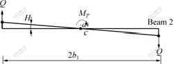
Fig.2 Schematic diagram of torsional deformation of three beams model
3 Method of modal test based on ambient excitation
During the experiment of modal test based on ambient excitation, the input for bridge structure due to vibration of foundation or wind was considered as a stationary random process approximatively, and response of bridge due to those excitations can be collected by UINO (unknown input and N points output) method, and the modal parameters can be obtained by methods which appropriate to ambient excitation[12-13]. The method of peak value and method of power spectral density function(PSD) for random response were combined to identify modal parameters.
3.1 Determination of rth modal frequency ωr
Let ωr and ζr denote the circular frequency and ratio of damp, respectively. {φr} is the corresponding mode of vibration, which can be written as
{φr}=[φ1r φ2r … φnr]T
Since there is a peak near every natural frequency in the frequency response function (FRF) curve, if the FRF diagram is replaced by PSD curve approximatively and every peak of PSD is assumed to be determined by only one modal mode, then the modal frequencies can be obtained by every peak of PSD curve.
3.2 Determination of rth modal mode of vibration
Let xi(i=1, …, n) represent the response output of position i, including test points and reference points, and [Sxx] represent the matrix of PSD, based on the theory of spectral analysis of random vibration[14], when ω=ωr then
 (13)
(13)
where  , mr is the rth genera- lized mass after mass matrix is decoupled.
Because the ratio of damp for cable-stayed bridge is generally less than 0.005[12], the following equation would be obtained:

When φjr=1, namely, all the modes of vibration are generized to j point, then
 (14)
(14)
According to Eqn.(14), any column of matrix [Sxx] corresponding to ωr is the rth modal mode of vibration {φr}.
3.3 Ratio of damp
Let ΔBr denote the frequency breadth between half
peak points of the PSD curve, and the ratio of damp (ζr) is assumed very small, then the ratio of damp can be obtained approximatively
 (15)
(15)
where ΔBr can be obtained by half-power method.
4 Comparision of modal test result with FEM solution
The dynamic mechanical behavior of Jingzhou Yangtze River was analyzed with three beams model, the former 20 natural frequencies and modes of vibration were obtained. The former 5 modal frequencies and modes were identified effectually in the modal test, and the most important modal parameters, such as longitudinal floating mode, first vertical flexural mode, first torsional mode, for cable-stayed bridge were determined. The results are listed in Table 1 and shown in Fig.3.
From Table 1, the errors of frequencies between test results and theoretical solutions are less than 10% mostly. The test results are very close to the theoretical solutions especially for the torsional mode, which demonstrates that the three beams model can fully simulate the stiffness distribution of girder with double ribs.
Table 1 Comparison of modal test results and FEM solutions for Jingzhou Yangtze River Bridge
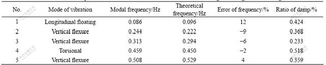
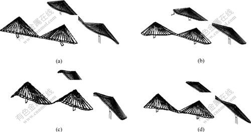
Fig. 3 First four modes vibration by theoretical dynamic analysis
(a) First mode of vibration(Longitudinal floating); (b) Second mode of vibration(Vertical floating); (c) Third mode of vibration(Vertical floating); (d) Fourth mode of vibration(Torsional)
5 Conclusions
1) By comparing with modal test results based on ambient excitation, the three beams model of cable-stayed bridge can fully simulate the stiffness distribution of girder with double ribs. The method to calculate the stiffness distribution of girder is also verified by modal test.
2) The test result of cable-stayed bridge demonstrates the validity of the combination method of peak value and PSD under ambient excitation. The errors of frequencies between the test results and theoretical solutions are less than 10% mostly, and the most important modal parameters for cable-stayed bridge are determined.
References
[1] MENG J Y, LIU E M, LIU Y. Dynamical response of skew highway bridges[J]. Journal of Earthquake Engineering, 2001, 5(2): 205-223.
[2] WILSON, JOHN C, LIU T. Ambient vibration measurements on a cable-stayed bridge[J]. Journal of Earthquake Engineering and Structure Dynamics, 1991, 20(11): 723-747.
[3] BROWNJOHN J M W, LEE J, CHEONG B. Dynamic performance of a curved cable-stayed bridge[J]. Engineering Structure, 1999, 21(11): 1015-1027.
[4] CASA J R. Full scale dynamic testing of the Alamillo cable-stayed bridge in Sevilla (Spain)[J]. Journal of Earthquake Engineering and Structural Dynamics, 1995, 24(1): 35-51.
[5] TAKENOUCHI K. Single pylons for curved cable-stayed bridges[J]. Structural Engineering International, 1998, 8(4): 269-272.
[6] LI Guo-hao. Research of Bridge and Structure Theory[M]. Shanghai: Shanghai Science and Technology Literature Press, 1983. (in Chinese)
[7] LI Zhong-fu, HUA Hong-xing, SONG Han-wen, et al. Parameters identification of linear structures undergoing ambient excitation using mode decomposition[J]. Journal of Shanghai Jiaotong University, 2001, 35(12): 1762-1765. (in Chinese)
[8] TIAN Zhong-chu, CHEN Chang-song, ZHEN Wang-an. Experimental modal analysis of steel box basket-hande arch bridge[J]. Journal of Vibration and Shock, 2004, 23(2): 44-47. (in Chinese)
[9] TROYANO L F, ARMISEN J M, SUAREZ M A A. The inclined towers of the Ebro and Lerez Bridge[J]. Structural Engineering International, 1998, 8(4): 258-260.
[10] ZHUGE Hung-cen, LI De-bao. Experimental studies for wind-induced vibration of a 30 m tall lamp post structure[J]. Engineering Mechanics, 1998, 15(2): 109-116. (in Chinese)
[11] LI Xiao-zhen, QIANG Shi-zhong. Vehicle-bridge dynamic analysis for long span highway and railway bi-purpose cable-stayed bridge[J]. Journal of Vibration and Shock, 2003, 22(1): 6-11. (in Chinese)
[12] CHEN Chang-song, TIAN Zhong-chu, ZHEN Wang-an, et al. Research of modal experiment technique of long-span cable-stayed bridge[J]. Chinese Journal of Civil Engineering, 2005, 38(10): 72-75. (in Chinese)
[13] CHEN Chang-song, YAN Dong-huang, TIAN Zhong-chu, et al. Optimal identification of modal parameters of long-span cable-stayed bridge with double-rib girder based on ambient excitation[J]. Journal of Vibration and Shock, 2006, 25(5): 158-161. (in Chinese)
[14] XU Xiu-zhong, HUA Hong-xing, CHEN Zhao-neng. Review of modal identification method based on ambient excitation[J]. Journal of Vibration and Shock, 2002, 21(3): 1-6.(in Chinese)
(Edited by CHEN Wei-ping)
Foundation item: Project(50608008) supported by the National Natural Science Foundation of China; project(20050536002) supported by the Specialized Research Fund for the Doctoral Program of Higher Education
Received date: 2006-05-21; Accepted date: 2006-07-27
Corresponding author: CHEN Chang-song, PhD; Tel: +86-731-5040248; E-mail: changsongchen@vip.sina.com

