J. Cent. South Univ. (2017) 24: 1881-1888
DOI: https://doi.org/10.1007/s11771-017-3595-5

Measurement and numerical analysis of influence of key stratum breakage on mine pressure in top-coal caving face with super great mining height
LI Meng(李猛), ZHANG Ji-xiong(张吉雄), HUANG Yan-li(黄艳利), GAO Rui(高瑞)
School of Mines, Key Laboratory of Deep Coal Resource Mining of Ministry of Education of China,China University of Mining & Technology, Xuzhou 221116, China
 Central South University Press and Springer-Verlag GmbH Germany 2017
Abstract: To analyze the influence of movement in shallow-buried working faces with large mining heights on mine pressure manifestation, the key stratum at a working face was categorised using the 1313 top-coal caving face with super great mining height under cover as a case study. The research combined theoretical analysis, field measurement, and numerical simulation to analyze the influencing mechanism of key stratum. Moreover, the research results were verified by numerical simulation and indicate that the sub-key stratum is prone to be broken to form a “cantilever beam” structure rather than a stable hinged structure during the excavation of working faces with super great mining heights. When the “cantilever beam” structure is unstable, a low pressure will occur on the working face, and the overlying strata will subside simultaneously with the sub-key stratum to induce the breakage of the primary key stratum: the breakage will further trigger the periodic breakage of sub-key stratum, causing a greater load on the working face. Finally, steps, and strength of weighting in the working face vary to be great or small alternatively. This is the main reason explaining why the 1313 working face shows strong mine pressure manifestation. The results provide theoretical and practical experience for forecasting and controlling mine pressure manifestation.
Key words: super great mining height; key stratum; cantilever beam; mine pressure manifestation; under cover
1 Introduction
There are numerous coal seams buried shallowly in western China. A coal seam with a thickness of 10 to 20 m is regarded as extremely thick. To improve the efficiency of mining therein, fully-mechanised mining with a super great mining height is widely adopted [1]. Compared with the working faces for thin and medium-thick coal seams, the spatial scope of the goaf at the working face for an extremely thick coal seam after mining increases significantly in addition to the increased caving height of the rock strata. Meanwhile, the range of the overlying strata influence on the working face increases and may cause accidents, such as support crushing, rib spalling, step convergence, or roof falling [2-4]. Thereby, to understand mine pressure manifestation in full-mechanized caving faces with super great mining height is essential.
At present, many scholars have studied rock strata movement in mining faces with high mining height in shallow coal seams: HUANG [5] established mechanical models for the first weighting and periodic weighting of a shallow coal seam and computing the support resistance of a support. GONG and JIN [6] researched the roof structure characteristics in fully- mechanised coalfaces with large mining height by using field measurement and similar simulation. Besides, they also built a mechanical model for the roof control of fully-mechanised coalfaces with large mining height. Through theoretical analysis and simulation experiments, JU et al [7] proposed modes for the “cantilever beam” structure of the key stratum in the working face with large mining height and assessed the influence thereof on the rock pressure in the stope. ZHANG et al [8] established a mechanical model for roof fractures in shallow-buried full-mechanized caving mining faces and deduced a criterion for roof fracture events. Taking a coal seam with a thickness of 6.0 m from the Zhangjiamao coal mine as an example, LAI et al [9] analyzed mine pressure manifestation in a fully-mechanised caving face with a large mining height by using a physical simulation. YU et al [10] acquired the failure characteristics for overburden strata movement in a fully-mechanised caving face with large mining height by in situ measurement. Little understanding of mine pressure manifestation of shallow-buried working faces with super-great mining heights exists. Meanwhile, it is common that there are single key stratum or multiple key stratum in the overlying rock above shallow coal seams in the western areas of China. The movement and breakage of key stratum will induce mine pressure manifestation at the working face. Thus, under the engineering background of 1313 top-coal caving face with super great mining height, based on key strata theory the mechanism of mine pressure manifestation was explored using theoretical analysis, field measurement, and numerical simulation to predict, and control, the mine pressure under similar conditions.
2 Geological conditions and mining pressure measurement
2.1 Geological conditions
1313 fully-mechanized caving face is located in the No. 13 coal seam in the lower-middle part of the Taiyuan Formation, where the coal seam thickness is 12 to 13.2 m and the average thickness is 12.6 m. The coal seam changes slightly over the region and is considered to be a stable, super-high seam with recoverable reserves of 1.41 million tons. Besides, the length of its working face is 150 m and the advancing strike length is 650 m (Fig. 1). Fully-mechanised caving is applied in the working face with a mining height of 3.2 m and a top-coal caving height of 9.4 m. ZF8000/23/35 sub-level caving hydraulic supports were used in the working face with a working resistance of 8000 kN and a support height of 2.3 to 3.5 m. The burial depth of the coal seam is 176 to 264 m. The immediate roof is mainly made of sandy mudstone, while the upper roof is mainly composed of fine sandstone. In addition, the baseboard is mudstone- based and the surface is covered by thick alluvium (Fig. 2).
2.2 Characteristics of mining pressure measurement
While mining the 1313 working face, six monitoring points were arranged to observe the working resistance of the hydraulic supports (see Fig. 3).
The measured pressures at the working face show that the first weighting interval of the working face is 38.6 to 42.3 m and the mean interval is 39.5 m during the first weighting. In periodic weighting, small and large weighting steps, and the strength of the working face vary alternately. The large weighting steps range from 13.2 m to 15.1 m and the average step is 14.4 m; while the small one step are between 8.5 and 11.2 m with an average of 9.6 m. Figure 4 shows the working resistance curve for No. 45 support. It can be seen that the dynamic load coefficient of the support is 1.32 to 1.49 with an average of 1.41. During weighting, most of the support is under its full-load working condition. Owing to the supporting resistance being insufficient, the safety valve is frequently opened. Meanwhile, the pressure in the high-pressure chamber of the support is released frequently so that the roof subsides to an average subsidence of 460 mm. Under these conditions, rib spalling occurs on a large scale, with waste rock, roof falls, step subsidence, etc. so that the support is almost crushed to produce strong mine pressure manifestation at the working face. Hence, it is urgent and necessary to study the mechanism of mine pressure manifestation in working face.
3 Distinguishing key stratum
3.1 Distinguishing method
Due to the differences in the layered characteristics of coal measures strata, the role of each stratum in the activities of the entire rock mass is different. For example, the hard strata carry the body and the skeleton, while the soft strata only play a role in loading and the dead weight is mainly borne by hard strata. Therefore, the rock stratum controlling all or partial rock mass activity is referred to as the key stratum [11]. When the key stratum is broken, the subsidence of all, or part, of the rock strata is mutually consistent, where the rock stratum controlling all strata movement is called the primary key stratum, while the one controlling local strata movement is known as the sub-key stratum [12]. Owing to the breakage of key stratum, all or local overlying rock strata will move at large to lead to significant strata movement (see Fig. 5).

Fig. 1 Layout of working face
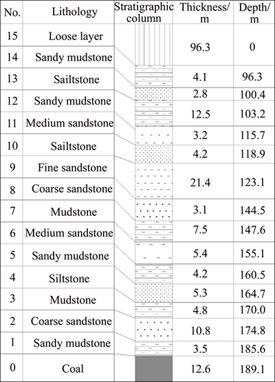
Fig. 2 Drill-log of working face
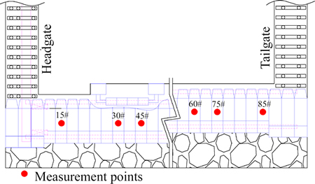
Fig. 3 Measurement points on face supports
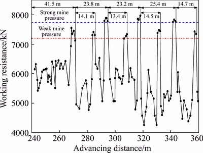
Fig. 4 Working resistance of 45# support
On the basis of key stratum theory, many studies have distinguished the position of the key stratum, and proposed a method of distinguishing key stratum through the following three steps [13]:
Step 1: To determine the positions of hard strata in overlying strata from bottom to top. The hard stratum here refers to the rock stratum whose deflection is less than that of the lower strata in the deformation, and it fails to coordinate with the deformation of lower strata. If the first layer is hard, the rock strata from second to mth layers are in coordination with its deformation, but the rock stratum on the (m+1)th layer is not coordinated with its deformation, the rock stratum on the (m+1)th layer is the second hard stratum. Owing to the rock strata from the first to the mth layers being in coordination with its deformation, the curvature of each stratum is the same. According to the principle of action of a composite beam, the load at the first hard stratum is:
 (1)
(1)
where hi, gi, and Ei are the thickness, bulk density, and elastic modulus of the ith rock stratum, respectively.
Considering the load produced by the m+1 rock stratum on the first hard stratum is:
 (2)
(2)
Owing to the (m+1)th rock stratum being a hard stratum, whose deflection is less than that of the lower strata, it is unnecessary for the rock strata, below the (m+1)th stratum, to bear the load of the strata above, then it can meet the condition:
 (3)
(3)
Substituting Eqs. (1) and (2) into Eq. (3), after simplification, it is seen that:
 (4)
(4)
where Eq. (4) is the equation distinguishing the locations of hard rock strata. The strata, from the first stratum above the coal seam, are calculated layer-by-layer and the calculation is stopped once Eq. (4) is satisfied. Then among the rock strata above the first rock stratum, the (m+1)th rock stratum is the first hard stratum, and m soft rock strata are included below the hard rock stratum. The next hard rock stratum is determined by the same method.

Fig. 5 Movement and breakage of key stratum
Step 2: To calculate the broken length of each hard rock stratum. The clamped beam model is used to give the broken length of the kth hard rock stratum, Lk as:
 (5)
(5)
where hk (k=1, 2, …, n) is the thickness of the kth hard rock stratum; σk is the tensile strength of the kth hard rock stratum; and qk is the loading borne by the kth hard rock stratum.
As indicated by Eq. (1), qk can be determined from
 (6)
(6)
where the subscript k (k=1, 2, …, n-1) represents the kth hard rock stratum; the subscript j stands for the layer number of the soft rock strata groups controlled by the kth hard rock stratum; mk is the number of soft rock strata controlled by the kth hard rock stratum; Ek,j, hk,j, and gk,j are the elastic modulus, layer thickness, and bulk density of the jth rock stratum among the soft rock strata group controlled by the kth hard rock stratum.
The topsoil is granular, with zero elastic modulus [13, 15]. If the thickness of the topsoil is H, and the bulk density is r, then the load on the nth hard rock stratum can be computed as:
 (7)
(7)
Step 3: To compare the broken length of each hard rock stratum according to the following principles to determine the key stratum.
1) If the kth hard rock stratum is a key stratum, its broken length should be less than that of all hard rock strata above it, namely, it meets the condition:
 k=1, 2, …, n-1 (8)
2) If the broken length of the kth hard rock stratum Lk is greater than that of the Lk+1th hard rock stratum above it, then the loading borne by the (k+1)th hard rock stratum is applied to the kth hard rock stratum, and then the broken length of the kth hard rock stratum is recalculated.
3) To verify Eq. (8) from the bottom most rock stratum, by layers: If Lk>Lk+1, the broken length of the kth hard rock stratum needs to be recalculated.
3.2 Case study
Combining the drill hole column of the 1313 working face, the physical and mechanical properties of its rock strata were measured (see Table 1).
Table 1 Physical and mechanical properties of rock strata at 1313 working face

The aforementioned method distinguishing key stratum was used to judge the key stratum of the 1313 working face. It was found that the second and the ninth stratum above the coal seam are key stratum: the ninth is the primary key stratum, and the second is the sub-key stratum. The first breaking interval of the primary key stratum and the sub-key stratum on the 1313 working face can be found from Eq. (9):
 (9)
(9)
where h is the thickness of the key stratum; σt is the tensile strength; and q is the pressure thereon. The periodic breaking interval of the primary key stratum and the sub-key stratum on the 1313 working face can be calculated by
 (10)
(10)
The parameters of key stratum are substituted into Eqs. (9) and (10), and then it can be found that the first and periodic breaking intervals of the primary key stratum are 63.3 m and 25.8 m, and those of the sub-key stratum are 38.7 and 15.8 m.
The breaking intervals of the primary key stratum are greater than that of the sub-key stratum, which means that the breakage of the sub-key stratum occurs before that of the primary key stratum. The breakage of the sub-key stratum will induce a small pressure on the working face, while the breakage of the primary key stratum will cause the greatest pressure on the working face. As a result, the working face suffers high amplitude cyclic stress fluctuations.
4 Mechanism of mine pressure manifestation
If a stable hinged structure is formed due to the breakage of sub-key stratum, it is likely to restrict the subsidence of overlying strata and bear the load of overlying strata, so as to reduce deformation and pressure at the working face. On the contrary, if sliding instability occurs after breakage of sub-key stratum, the overlying strata subsides along with the sub-key stratum to result in the breakage of the primary key stratum, which has a significant effect on the working face. Therefore, it is necessary to determine the stability of the sub-key stratum. The rotating subsidence of key stratum is shown in Fig. 6.

Fig. 6 Rotating subsidence of key stratum
The spatial displacement between the immediate roof after its collapse and the upper key stratum [14] is:
 (11)
(11)
where △ is the rotating subsidence of the block given the breakage of key stratum; M is the mining height; Kp is the broken expansion coefficient of collapsed rocks; and
 is the thickness of the strata below the key stratum.
If the required limiting rotation of the block with the breakage of key stratum can form a stable “voussoir beam” structure, the displacement becomes △max, when △>△max, the key stratum is at the caving zone and form a “cantilever beam” structure. Through the mechanical model of the deformation instability of a “voussoir beam” structure, it can be found that:
 (12)
(12)
where h is thickness of the key stratum; l is the broken length of the key stratum; q is the load borne by the key stratum; and σc is the compressive strength of the block with the breakage of the key stratum.
The condition for forming a stable hinged structure [15] at the working face is:
 (13)
(13)
Equation (13) is used to distinguish whether a stable hinged structure can be formed after breakage of the sub-key stratum. On the condition that the broken expansion coefficient of the collapsed rocks in the immediate roof Kp is 1.3, and the average bulk density of rock strata is 25 kN/m3, then Eq. (11) gives △=11.6 m. Moreover, if the broken length l and the compressive strength σc of the sub-key stratum are 15.8 m and 38 MPa respectively, Eq. (12) gives △max=7.8 m, and △>△max, which suggests that the sub-key stratum fails to form a stable hinged structure but instead forms a “cantilever beam” structure.
When the “cantilever beam” structure is broken, the locus of rotation is large, so it is apt to cause sliding instability and form a “step beam” structure [16] so as to produce significant separation between the overlying strata and primary key stratum. As a result, the primary key stratum is broken so that cyclic stress is imposed on the working face because of the breakage of sub-key stratum, which somewhat influences the support at the working face, and thus the load is not great. The large pressures are caused by the breakage of primary key stratum. As the broken strata have an impact on the support at the working face, the mine pressure manifestation effect on the working face is dramatic. Moreover, the supporting resistance on the working face is large. Thus, a single key stratum is broken during small periodical pressure cycles, while the breakage occurs in the two key stratum simultaneously during the large amplitude cycles [17]. According to the cycle, finally, the weighting steps and strength on the working faces present a similar trend.
5 Numerical simulation
5.1 Modelling
With the 1313 full-mechanised caving face as an engineering background, UDEC numerical simulation software was used to investigate the influence of, and mechanism causing, mine pressure manifestation in each key stratum (see Fig. 7). The length of the model was 850 m, including 100 m wide coal pillars at both ends: the height of model was 100 m. In addition, the loose strata imposed a uniformly distributed load of 1.6 MPa on the upper boundary of the model; while the left, and right-hand sides, and the bottom of model were subjected to displacement constraints. Furthermore, a Mohr- Coulomb model was used to represent the coal-rock mass. Monitoring lines were arranged at the primary key stratum, sub-key stratum, and coal seam to check the displacement and stress while advancing the working face.

Fig. 7 Numerical calculation model
5.2 Results and analysis
Figure 8 shows the characteristics of strata movement while advancing the 1313 working face.
Figure 8 shows that, when the working face was advanced by 14 m, the immediate roof fell in an arch-like way, and the rock strata above the sub-key stratum were little affected by mining activities. When the working face was advanced to 39 m, the sub-key stratum broke for the first time and it moved under a sliding instability to form a “step beam” structure. Meanwhile, the rock strata controlled by the sub-key stratum sank with it to apparently separate the primary key stratum so as to produce a low pressure on the working face. As the working face was mined to 54 m, the sub-key stratum experienced the first periodic breakage to form a “step beam” structure. Besides, the separation between the rock strata controlled by the sub-key stratum and the primary key stratum increased to induce a low pressure on the working face. When the working face was advanced to 65 m, the primary key stratum subsided by rotating and it broke for the first time. As the separation was gradually closed, the sub-key stratum broke in the second cycle to induce a larger pressure on the working face. With the advance of the working face to 81 m, the third periodic breakage happened to the sub-key stratum to form a “step beam” structure. In this case, the overlying strata separated from the primary key stratum to lead to a low pressure on the working face. While when the working face was advanced to 89 m, the rotating subsidence occurred in the primary key stratum to induce the first periodic breakage, and the sub-key stratum experienced its fifth periodic breakage to form a “step beam” structure. The working face suffered significant stress.
Figure 9 shows the distribution of abutment stress during the advance of the 1313 working face.
As shown in Fig. 9, in general, the sub-key stratum breaks earlier than the primary key stratum. Besides, the first breakage and periodic breakages of the former will induce low pressures in the working face. In addition, the breakage of the primary key stratum can cause the sub- key stratum to break simultaneously; its first breakage, and later periodic breakages, are expected to induce a high pressure in the working face. Therefore, the small and large weighting steps and strength in the working face alternately change, which agreed with the theoretical analysis and measured results.
6 Conclusions
1) The mine pressure manifestation in fully-mechanised caving faces with large mining heights differs from that of ordinary fully-mechanised caving faces. The weighting steps and strength in the 1313 fully- mechanised caving face show a periodic fluctuation between low and high stress, where the allied average weighting steps are 14.4 m and 9.6 m respectively. These phenomena, such as waste rock, roof falling, or step subsidence, happen to the working face, which is close to crushing the support under such intense mine pressure manifestation.
2) After the breakage of the sub-key stratum in such fully-mechanised caving faces, a “cantilever beam” structure is formed, which is vulnerable to sliding instability. On this basis, the overlying strata sank together with the sub-key stratum to cause breakage of the primary key stratum. The breakage of the primary key stratum will further result in the early breakage of the sub-key stratum. Finally, the alternative changes in weighting steps and strength on the working face were manifest.
3) The strong mine pressure manifestation in fully- mechanised caving faces with super great mining heights is mainly caused by the breakage of the primary key stratum and sub-key stratum. The working face will produce little pressure owing to the breakage of the sub-key stratum, while the simultaneous breakage of the primary key stratum and sub-key stratum is expected to induce higher pressures on the working face.
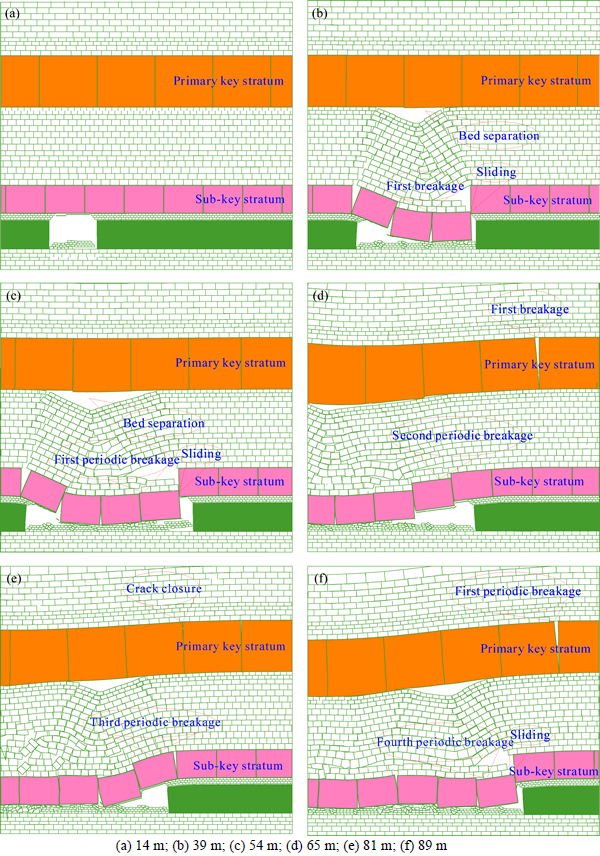
Fig. 8 Strata movement on 1313 working face:

Fig. 9 Distribution of abutment stress
References
[1] WANG Jin-hua. Key technology for fully-mechanized top coal caving with large mining height in extra-thick coal seam [J]. Journal of China Coal Society, 2013, 38(12): 2089-2098. (in Chinese)
[2] YUN Dong-feng, LIU Zhu, CHENG Wen-dong, FAN Zheng-dong, WANG Dong-fang, ZHANG Yuan-hao. Monitoring strata behavior due to multi-slicing top coal caving longwall mining in steeply dipping extra thick coal seam [J]. International Journal of Mining Science and Technology, 2017, 27(1): 179-184.
[3] CHANG Ju-cai, XIE Guang-xiang, ZHANG Xue-hui. Analysis of rib spalling mechanism of fully-mechanized top-coal caving face with great mining height in extra-thick coal seam [J]. Rock and Soil Mechanics, 2015, 36(3): 803-808. (in Chinese)
[4] GUO Xin-shan, LIU Jin-hai, JIANG Fu-xing. In-situ observation and numerical analysis of roof movement features of fully-mechanized sublevel caving face with deep alluvium [J]. Journal of Mining & Safety Engineering, 2015, 32(3): 401-406. (in Chinese)
[5] HUANG Qing-xiang. Structural analysis of main roof stability during first weighting in longwall face [J]. Chinese Journal of Rock Mechanics & Engineering, 1998, 17(5): 521-526. (in Chinese)
[6] GONG Pei-lin, JIN Zhong-ming. Mechanical model study on roof control for fully-mechanized coal face with large mining height [J]. Chinese Journal of Rock Mechanics & Engineering, 2008, 27(1): 193-198. (in Chinese)
[7] JU Jin-feng, XU Jia-lin, WANG Qing-xiong. Cantilever structure moving type of key strata and its influence on ground pressure in large mining height workface [J]. Journal of China Coal Society, 2011, 36(12): 2115-2120. (in Chinese)
[8] ZHANG Jian-gong, MIAO Xie-xing, HUANG Yan-li, LI Meng. Fracture mechanics model of fully mechanized top coal caving of shallow coal seams and its application [J]. International Journal of Mining Science & Technology, 2014, 24(3): 349-352.
[9] LAI Xing-ping, SHAN Peng-fei, ZHENG Jian-wei, CAO Jian-tao, CUI Feng, WANG Chun-long. Physical simulation on strata behavior of large mining height fully mechanized face in shallow-buried and thick seam [J]. Journal of Mining & Safety Engineering, 2014, 31(3): 418-423. (in Chinese)
[10] YU Bin, ZHAO Jun, KUANG Tie-jun, MENG Xiang-bin. In situ investigations into overburden failures of a super-thick coal seam for longwall top coal caving [J]. International Journal of Rock Mechanics & Mining Sciences, 2015, 78: 155-162.
[11] LI Yang, ZHU En-guang, ZHANG Kang-ning, LI Ming-hao, WANG Jia-xing, LI Cheng-kun. Longwall mining under gateroads and gobs of abandoned small mine [J]. International Journal of Mining Science and Technology, 2017, 27(1): 145-152.
[12] QIAN Ming-gao. Key stratum theory of overlying strata control [M]. Xuzhou: China University of Mining & University Press, 2003. (in Chinese)
[13] XU Jia-lin, QIAN Ming-gao. Method to distinguish key strata in overburden [J]. Journal of China University of Mining & Technology, 2000, 29(5): 463-467. (in Chinese)
[14] QIAN Ming-gao, SHI Ping-wu, XU Jia-lin. Ground pressure and strata control [M]. Xuzhou: China University of Mining & University Press, 2010. (in Chinese)
[15] JU Jin-feng, XU Jia-lin. Surface stepped subsidence related to top-coal caving long wall mining of extremely thick coal seam under shallow cover [J]. International Journal of Rock Mechanics & Mining Sciences, 2015, 78: 27-35.
[16] GUO Wei-bin, LIU Chang-you, WU Feng-feng, YANG Pei-ju, WU Sheng-fu. Analyses of support crushing accidents and support working resistance in large mining height workface with hard roof [J]. Journal of China Coal Society, 2014, 39(7): 1212-1219. (in Chinese)
[17] XU Jia-lin, JU Jin-feng. Structural morphology of key stratum and its influence on strata behaviors in fully-mechanized face with super-large mining height [J]. Journal of china coal society, 2011, 30(8): 1547-1556. (in Chinese)
(Edited by DENG Lü-xiang)
Cite this article as: LI Meng, ZHANG Ji-xiong, HUANG Yan-li, GAO Rui. Measurement and numerical analysis of influence of key stratum breakage on mine pressure in top-coal caving face with super great mining height [J]. Journal of Central South University, 2017, 24(8): 1881-1888. DOI: https://doi.org/10.1007/s11771-017-3595-5.
Foundation item: Project(2015-29) supported by Jiangsu Distinguished Professor, China; Project(BRA2015311) supported by the Jiangsu Province Fourth 333 Engineering, China
Received date: 2015-12-14; Accepted date: 2016-05-11
Corresponding author: ZHANG Ji-xiong, Professor, PhD;Tel: +86-13912005505;E-mail: zjxiong@163.com

