
Crystallographic research of spangle on hot dip galvanized steel sheets
LU Jin-tang(¬����), WANG Xin-hua(���»�), CHE Chun-shan(����ɽ),
KONG Gang(�� ��), CHEN Jin-hong(�½���), XU Qiao-yu(�����)
College of Materials Science and Engineering, South China University of Technology, Guangzhou 510640, China
Received 7 July 2006; accepted 16 January 2007
Abstract: The spangles on hot dip galvanized steel sheet were investigated on an X-ray diffraction(XRD) meter by the rotating crystal method. The correlations between the crystallographic orientations of spangles and their morphologies were analyzed. The results show that the correlation can be classified into three types: ��=0?, 0?���£�90? and ��=90? by ��. Crystallographic model of single spangle under the ideal condition was established based on the experimental results. The correlation between �� and �� can be deduced by their geometric relation as an equation.
Key words: hot dip galvanizing; crystal growth; solidification; spangle
1 Introduction
Spangles on hot dip galvanized(HDG) coatings are characterized by typical dendrite single-crystals[1]. Spangles are produced on the galvanized steel sheets when certain alloying elements, such as Pb, Sb, Sn, Bi, Al, are added into zinc bath. This is because those alloying elements not only change the size of zinc grain by altering the surface tension of liquid zinc, nucleus incidence and growing rate of zinc grain, but change the orientation of zinc grain[2-4]. Added alloy elements in zinc can affect the properties of the zinc alloy[5-6]. Spangles are the symbol for HDG sheets, and in recent years, galvanizing articles with spangles are increasingly required by customers[7-9].
Zinc coating with spangles is a decorative coating, and its appearance is closely related to the orientation of zinc crystals and the distribution of alloy elements in the coating[10-12]. It is found that bright spangles present a texture of basal plane (0001), with a smooth surface and little second phase from segregation. However, dull spangles have a pyramidal texture with any of the following planes:  or a prismatic texture with the plane
  parallel to the steel surface, having a rough surface. And the second phases are segregated from the coating surface where they precipitate. Because spangles are great zinc crystals by naked eye and are segregated by alloying elements in dull segments, these will do harm to the mechanical properties and corrosion resistance. The difference of zinc crystallographic orientation on the surface makes the close-packing atoms on the surface and the segregation of alloy elements change, resulting in the different effect on the mechanical properties and corrosion resistance of coatings[12-16].
In recent years, many researches were reported on the formation mechanism, the mechanical and corrosive properties of spangles, which have connection with the orientation of zinc crystals. For the research on crystallographic orientation of spangles, most works were focused on the texture[17-19], little on the single spangle. In the present investigation, single spangle with different morphologies produced in Zn-0.15Al-0.2Sb bath was discussed on an X-ray diffraction(XRD) meter by rotating crystal method separately. Crystallographic model of single spangle under the ideal condition was established.
2 Experimental
The 100 mm��60 mm��1.2 mm steel sheet specimens were galvanized in a bath of Zn+0.15%Al+0.2% Sb in a hot dip galvanizing(HDG) simulator at 450 ��. Those specimens with spangles were observed on metalloscope and their ��-angles between primary dendrite arms were measured. Three samples with only one typical spangle morphology, labeled with ��, �� and ��, were cut from the galvanized specimens and analyzed by X-ray diffractometer (D max/��A, Cu K��, 20 kV). According to XRD results, pole figures of the single crystals of these spangles were drawn to characterize the crystallization orientation of each spangle.
XRD experiments were done as follows: at first, place a sample on the sample stage of X-ray diffractometer and set up a space coordinate system x-y-z on the basis of the surface as the plane xOy, then rotate the sample around axis Oz (normal to the plane xOy), as shown in Fig.1(a). Apparently, only the zone planes belonging to the zone axis parallel to axis Oy can produce diffraction peak reflection condition. It is assumed that pole figures of a zinc single crystals are placed on plane xOy so that their centers coincide. The rotation of the sample around axis Oz is equivalent to pole figure of the single crystal of spangle rotating around axis Oz (Fig.1(b)). It is deduced that the crystal plane will produce diffraction peaks in XRD pattern if its pole point (hklw) lies on the xx�� by the rotating of pole figure, as shown in Fig.1(b).
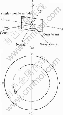
Fig.1 Schematic diagram of experiment principle (a) and rotation of pole figure of single spangle around axis Oz (b)
It is known from diffraction data of zinc crystallography theory[13] that no diffraction peak appears when 2�� is smaller than 30?, and all diffraction peaks with 2�� beyond 80? are weak. So 2�� is taken from 30? to 80? in present investigation.
3 Results and discussion
3.1 Morphology and XRD analysis
Fig.2(a) shows the micrograph of a snow-flake spangle, labeled with ��. The spangle �� displays a six- fold star dendrite morphology with 60? angles between the primary dendrite arms. It has a bright surface and remarkable dendrite structure. The secondary dendrite arms grow laterally away from the trunk well. XRD result reveals that all the five diffraction peaks belong to the zone axis  ,and the diffraction peak of plane (0001) is the most intense, as shown in Fig.2(b).
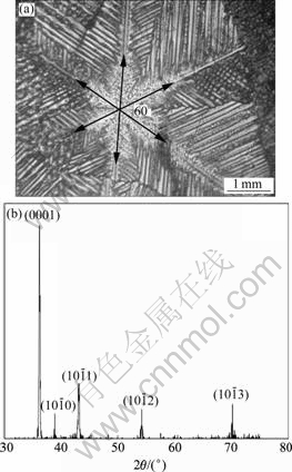
Fig.2 Micrograph (a) and X-ray diffraction pattern (b) of snow- flake spangle ��
Fig.3(a) shows the micrograph of an inclined dendrite spangle, labeled with ��. The spangle �� displays a dull and rough surface without remarkable dendrite structure on the left half, while a bright and clear dendrite structure, even the secondary dendrite arms appear clearly on the right half. As compared with spangle��, the 60? symmetry dendrite structure disappears and the two largest �� angles are equal to 95?. XRD result reveals that the diffraction peak of  is much more intense than the others, as shown in Fig.3(b).
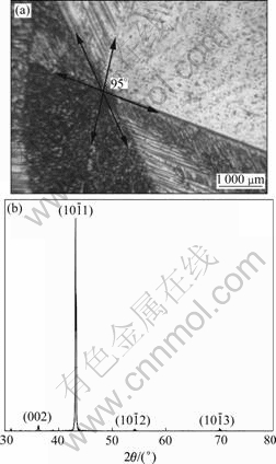
Fig.3 Micrograph (a) and X-ray diffraction pattern (b) of inclined dendrite spangle ��
Fig.4(a) shows the micrograph of an orthogonal-dendrite spangle, labeled with ��. The spangle �� displays a dull and rough surface entirely with just four primary dendrite arms of 90? �� angle, clear secondary dendrite arms that are vertical to emanate. XRD result reveals that only planes  and
and  produce peaks, as shown in Fig.4(b).
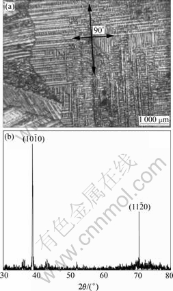
Fig.4 Micrograph (a) and X-ray diffraction pattern (b) of orthogonal-dendrite spangle ��
3.2 Pole figure analysis
It is known from the diffraction pattern of zinc powder that only six crystal planes produce diffraction peaks when 2�� is ranged from 30? to 80?. They are the planes of (0001),
 and
and  which were exactly captured in previous experiments. For powder samples, the diffraction peak of plane
 is the strongest, the diffraction peaks of planes (0001),
  and
and are the second strongest, the diffraction peak of
  is the third strongest.
In Fig.2(b), the planes (0001), 
 andproduce peaks, which are zone planes belonging to the zone axis
  and whose pole points in the (0001) pole figure all lie on the common great circle xOx��, as shown in Fig.5(a), which
shows the pole figure after the clockwise rotation by 30? of the standard zinc (0001) pole figure. It is deduced that the basal plane (0001) is aligned parallel to the steel sheet surface almost perfectly and the six fast growing  directions are all parallel to the steel sheet surface, which corresponds to the six primary dendrite arms in Fig.2(a) and is in good agreement with the 60? symmetry dendrite structure. The position of the zinc single crystal on the steel sheet surface is sketched in Fig.5(b). The six alike diffraction patterns can be gained while the sample is rotated from 0? to 360?.
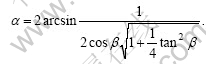
As shown in Fig.3(a), the standard six-fold stared shape is elongated along some direction and the �� angle is increased to 95? due to the inclination of the basal plane (0001) on the steel sheet surface. Fig.6(a) shows the relation between each crystallographic orientation (corresponding to each primary arm of spangle) and the c-axis of spangle. The correlation between �� and �� can be deduced by their geometric relation as follows:
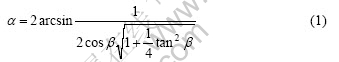
where �� is the angle between primary dendrite arms of spangles, �� is the angle between the basal plane (0001) and the steel sheet surface. The calculated values of �� as a function of �� are shown in Fig.6(b).
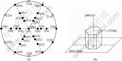
Fig.5 Pole figure (a) and schematic model of position of spangle �� on steel sheet surface (b)
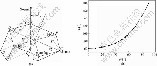
Fig.6 Schematic diagram of correlation between �� and �� (a) and curve of �� as function of �� (b)
It is known from Fig.6(b) that the basal plane (0001) of spangle �� inclines by 58? from the steel sheet surface. The pole figure of spangle II can be obtained by rotating Fig.5(a) by 58? along the  direction, as shown in Fig.7(a). In Fig.3(b), the intensity of plane
  is extremely strong, while the others are nearly close to zero, which corresponds to the great circle xOx�� where only
  pole point lies, as shown in Fig.7(a). This means that the six fast growing
  directions are no longer parallel to the steel sheet surface. Therefore an inclined dendrite spangle is formed, and the four alike diffraction patterns can be gained while the sample is rotated from 0? to 360?.
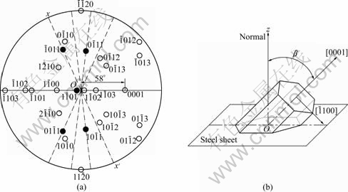
Fig.7 Pole figure (a) and schematic model of position of spangle �� on steel sheet surface (b)
In Fig.4(b), the planes  and
and  belong to the zone axis [0001], and their pole points lie on the common circle xOx��, as shown in Fig.8(a). Fig.8(a) is the pole figure gained by inclining Fig.5(a) by 90? along the
  direction. It is inferred that the basal plane (0001) is perpendicular to the steel sheet plane as shown in Fig.8(b). Under such circumstances, only the two of six fast growing directions
 and the other two <0001> directions can develop well and orthogonal- dendrite structure is formed. That is why the angle �� between arms equals 90? instead of 180? that was calculated by the angle �� between the arms of directions in Fig.6. The two alike diffraction patterns could be gained while the sample is rotated from 0? to 360?. The entire orthogonal-dendrite spangle should be the rhombus shape because the growing rate of the arms is faster than that of the <0001>. This difference is due to the anisotropy of the solid-liquid
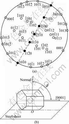
Fig.8 Pole figure (a) and schematic model of position of spangle �� on steel sheet surface (b)
interfacial energy (��s/l), which is smaller for the (0001) plane (about 70 mJ/m2) than for the  plane (about 100 mJ/m2) [19].
4 Conclusions
1) Each spangle represents a single-crystal zinc grain. The possible orientation of the basal plane (0001) on the steel sheet surface determines the morphology of the spangle. The correlation between the angle �� between the arms and the inclination angle �� on the steel sheet surface is denoted by the following equation:
2) Spangles may be categorized into three types according to ��: �� �£�0?,  zone planes produce diffraction peaks, in which the diffraction peak of the plane (0001) is the most intense, the spangle presents 60? symmetry dendrite structure and shiny surface, usually called snow-flake or six-fold star; �� 0?���£�90?, almost only plane
  produces diffraction peak, 60? symmetry of the dendrite structure disappears, and the spangle presents feathery structure or shiny/dull divided morphology; �� ��=90?, <0001> zone planes
  and
and  produce diffraction peaks, and the spangle presents dull and rough orthogonal-dendrite morphology.
3) Zinc solidification in hot dip galvanized coatings occurs by dendrite crystallization. Dendrite arms grow in preferred crystallographic directions, which are the fast growth directions in growth kinetics, and the most commonly observed directions for zinc are  secondly <0001>.
References
[1] MARDER A R. Metallurgy of zinc-coated steel [J]. Progress in Materials Science, 2000, 45(3): 191-271.
[2] LIU Y H, TANG N Y. Thermodynamic explanation of spangle formation [C]//Galvatech ��04 Conference Proceedings. Chicago: AISI, 2004: 941-949.
[3] FASOYINU F A, WEINBERG F. Spangle formation in galvanized steel sheet coatings [J]. Metal Trans B, 1990, 21(6): 549-558.
[4] PAVLIDOU E, PISTOFIDIS N, VOURLIAS G, STERGIOUSDIS G. Modification of the growth-direction of the zinc coating associated with element additions to the galvanizing bath [J]. Materials Letter, 2005, 59: 1619-1622.
[5] LI Xin-hai, LIANG Jiang-yu, GUO Bing-kun. Electrodeposition of corrosion-resistant zinc-alloy powder from alkaline solution [J]. Journal of Central South University of Technology, 1998, 5(11): 75-78.
[6] CHEN Wen-min, ZHANG Li. The corrosion characteristics of zinc lead alloys and zinc indium alloys in KOH solution [J]. Journal of Central South University of Technology: Natural Science, 2000, 31(5): 415-418. (in Chinese)
[7] MCDEVITT E T. Aluminum-Zinc Alloy Composition Spangle for Hot-Dipping Steel Products, Method and Product Obtainable Thereof [P]. USA, US6689489. 2004-03-03.
[8] MCDEVITT E T. Composition for Controlling Spangle Size, a Coated Steel Product, and a Coating Method [P]. Europe, EP1428898. 2004-07-06.
[9] ZERVOUDIS J, DUARTE V M, POAG G W. Process and Alloy for Decorative Galvanizing of Steel [P]. Europe, EP1428898. 2004-07-06.
[10] BIBER H E. Scanning Auger microprobe study of hot-dipped regular-spangle galvanized steel [J]. Metal Trans A, 1988, 19(6): 1603-1608.
[11] RODNYANSKY A, WARBURTON Y J, HANKE L D. Segregation in hot-dipped galvanized steel [J]. Surface and Interface Analysis, 1999, 29(11): 215-220.
[12] ZAPPONI M, QUIROGA A, PEREZ T. Segregation of alloying elements during the hot-dip coating solification process [J]. Surface and Coatings Technology, 1999, 122(12): 18-20.
[13] JAFFREY D, BRONE J D, HOWARD T J. The cracking of zinc spangles on hot-dipped galvanized steel [J]. Metal Trans B, 1980, 11(12): 631-635.
[14] VOURLIAS G, PISTOFIDIS N, STERGIORDIS G, PAVLIDOU E, TSIPAS D. Influence of alloying elements on the structure and corrosion resistance of galvanize coatings [J]. Phys Stat Sol, 2004, 201(7): 1518-1527.
[15] VOURLIAS G, PISTOFIDIS N, STERGIORDIS G, TSIPAS D. The effect of alloying elements on the crystallization behavior and on the properties galvanized coatings [J]. Cryst Res Technol, 2004, 39(1): 23-29.
[16] SINGH A K, JHA G, CHAKRABARTI S. Spangle formation on hot-dip galvanized steel sheet and its effects on corrosion-resistant properties [J]. Corrosion, 2003, 59(2): 189-196.
[17] SEMOROZ A, STREZOV L, RAPPAZ M. Orientation domains and texture in hot-dipped galvanized coatings [J]. Metal Trans A, 2002, 33(8): 2695-2701.
[18] SERE P R, CULCASI J D, ELSNER C I, DI SARLI A R. Relationship between texture and corrosion resistance in hot-dip galvanized steel sheets [J]. Surface and Coatings Technology, 1999, 122(6): 143-149.
[19] SEMOROZ A, STREZOV L, RAPPAZ M. Application of the phase�Cfield method to the solidification of hot-dipped galvanized coatings [J]. Metal Trans A, 2000, 31(2): 487-495.
Corresponding author: LU Jin-tang; Tel: +86-20-85511540; E-mail: mcjtlu@scut.edu.cn
(Edited by YANG Hua)

