J. Cent. South Univ. (2016) 23: 2354-2363
DOI: 10.1007/s11771-016-3294-7

Effects of nonlinear strength parameters on stability of 3D soil slopes
GAO Yu-feng(�����)1, WU Di(���)1, 2, ZHANG Fei(�ŷ�)1, 3, QIN Hong-yu(�غ���)4, Zhu De-sheng(���ʤ)1
1. Key Laboratory of Ministry of Education for Geomechanics and Embankment Engineering(Hohai University), Nanjing 210098, China;
2. School of Civil Engineering and Architecture, Qingdao Binhai University, Qingdao 266555, China;
3. Key Laboratory of Failure Mechanism and Safety Control Techniques of Earth-rock Dam of the Ministry of Water Resources, Nanjing 210029, China;
4. School of Computer Science, Engineering and Mathematics, Flinders University, Adelaide SA 5001, Australia
 Central South University Press and Springer-Verlag Berlin Heidelberg 2016
Abstract: Actual slope stability problems have three-dimensional (3D) characteristics and the soils of slopes have curved failure envelopes. This incorporates a power-law nonlinear failure criterion into the kinematic approach of limit analysis to conduct the evaluation of the stability of 3D slopes. A tangential technique is adopted to simplify the nonlinear failure criterion in the form of equivalent Mohr-Coulomb strength parameters. A class of 3D admissible rotational failure mechanisms is selected for soil slopes including three types of failure mechanisms: face failure, base failure, and toe failure. The upper-bound solutions and corresponding critical slip surfaces can be obtained by an efficient optimization method. The results indicate that the nonlinear parameters have significant influences on the assessment of slope stability, especially on the type of failure mechanism. The effects of nonlinear parameters appear to be pronounced for gentle slopes constrained to a narrow width. Compared with the solutions derived from plane-strain analysis, the 3D solutions are more sensitive to the values of nonlinear parameters.
Key words: three-dimensional slope; nonlinear failure criterion; limit analysis; stability; critical slip surface
1 Introduction
The linear Mohr-Coulomb (MC) failure criterion is always used in the traditional methods for stability analysis of earth slopes. In fact, the failure envelopes for many kinds of soils are curved, especially in the range of small normal stresses. This phenomenon has been observed in many experimental results [1-5]. According to the obtained results, various nonlinear failure criteria have been proposed to fit the curved failure envelopes [4-9]. Among these criteria, the power-law relations of nonlinear failure criteria (e.g., MELLO [6]; ZHANG and CHEN [8]; BAKER [9]) are commonly acceptable and have been widely applied into the assessment of slope stability.
One type of the power-law failure criteria is the simple power-law failure criterion, whose failure envelope is passing through the origin. The simple power-law failure criterion was originally suggested for rockfills by MELLO [6] and for colliery spoils by TAYLOR [10]. Afterwards, some researchers applied such a failure criterion into the conventional limit equilibrium (LE) method, to assess the stability of soil slopes and investigate the effects of nonlinear envelope on the slope safety and corresponding critical slip surface [7, 11-12]. Another commonly used type is the general power-law failure criterion, as proposed by ZHANG and CHEN [8] and BAKER [9]. The general power-law failure criterion is characterized by an initial cohesion at the origin, which is more appropriate for cohesive soils. Many attempts have been made to extrapolate the application of this power-law failure criterion in the stability analysis of soil slopes. The limit analysis (LA) method was widely used to evaluate the stability of soil slopes with the general power-law failure criterion [8, 13-17]. Besides, BAKER [18] combined this power-law failure criterion into a rigorous variational LE approach for the stability analysis of slopes. Moreover, the general power-law failure criterion has also been used in some other numerical methods to conduct the assessment of slope stability [19-21].In above-mentioned studies, the power-law failure criteria were used only for the evaluation of the stability of two-dimensional (2D) slopes. However, actual slope stability problems have the 3D characteristics and the curved failure envelopes. Therefore, performing 3D analysis using the nonlinear failure criterion will provide better representation of their actual values. In the literature, JIANG et al [22] combined the simple power-law failure criterion into the 3D LE method to analyze the stability of slopes. DENG et al [23] conducted the LE stability analysis of 3D slopes using the general power-law failure criterion. Although the existing studies considered the nonlinear failure criterion in the 3D LE method for the stability analysis of slopes, less attention has been paid to the effects of nonlinear parameters on the 3D slope stability, particularly on the critical slip surface.
This work incorporates the power-law nonlinear failure criterion into an alternative approach of upper-bound LA. A rotational 3D failure mechanism proposed by MICHALOWSKI and DRESCHER [24] is adopted here, to explore the 3D effects on the slope stability. Meanwhile, an efficient optimization procedure is used to obtain the upper bounds of slope stability and the corresponding critical slip surfaces. The calculated results are presented in the form of figures and tables to investigate the influences of the nonlinear parameters on the assessment of slope stability.
2 Limit analysis of 3D slope stability
2.1 Power-law nonlinear failure criterion
Many studies were conducted by using a nonlinear failure criterion with zero cohesion intercept at zero normal stress. Such a criterion is more suitable for uncemented and unbonded soils. However, the cohesive soils can sustain an initial cohesion and a limit tensile stress. The assumption of zero strength at zero stress is no longer valid. For cohesive soils, a general power-law failure criterion with an initial cohesion was proposed by ZHANG and CHEN [8]. This nonlinear criterion is widely acceptable and has been utilized in the slope stability analysis [3, 13-17, 19].
The power-law failure criterion can be expressed as
 (1)
(1)
where t and sn are shear and normal stresses on the failure surface, respectively. The parameters m, c0 and st are the nonlinear parameters and their values can be determined by tests. The parameter m is the nonlinearity coefficient, c0 is the initial cohesion of soil at zero stress, and st is the absolute value of tensile stress when t is equal to zero, as shown in Fig. 1. When m = 1.0, Eq. (1) is reduced to the well-known MC failure criterion with the identifications c=c0 and tanf=c0/st. It should be noted that the value of the parameter m must satisfy m��1.0, and the parameters c0 and st have to be larger than zero.
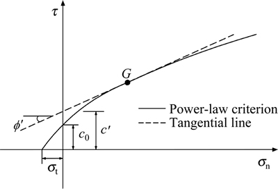
Fig. 1 Power-law failure criterion and its tangential line
2.2 Tangential technique
In the kinematic approach of LA, a nonlinear failure criterion is difficult to be directly used in the calculations of the rate of work done by soil weight and the rate of internal energy dissipation. To avoid the difficulty, DRESCHER and CHRISTOPOULOS [13] proposed a tangential technique, which was then developed by YANG and YIN [14]. The nonlinear failure envelope is replaced by a simple tangential line at some point G in the form of the equivalent MC strength parameters, as shown in Fig. 1. The least upper-bound solution can be obtained by minimizing the limit load with respect to the location of the tangency point. Thus, the obtained solution will be the upper bound, which is equal to or larger than the actual limit load. The equation of tangential line at some point G (in Fig. 1) can be expressed as
 (2)
(2)
where t and sn are the shear and normal components of the stress vector, respectively;  is the equivalent friction angle; and c�� is the equivalent cohesion, the intercept of the tangential line on the t-axis. As YANG and YIN [14] presented, the equivalent cohesion c�� can be derived by
 (3)
(3)
It can be seen that the expression of c�� is a function of . This equation will then be employed in the 3D LA method. As shown in Eq. (3), it can be found that the value of the parameter m must be greater than 1.0.
2.3 Kinematic approach of limit analysis with 3D failure mechanism
In the strict framework of upper-bound LA, the key element of 3D slope stability analysis is an admissible failure mechanism for 3D slope collapses. MICHALOWSKI and DRESCHER [24] proposed a 3D admissible rotational failure mechanism for slopes in homogeneous and isotropic cohesive/frictional soils obeying the MC failure criterion. However, the 3D rotational mechanism is limited to failures passing through the slope toe and cannot be constructed for slopes constrained to a narrow width. GAO et al [25] thus extended the 3D failure mechanism to include the face failure and base failure. This modified 3D failure mechanism is adopted here to conduct the stability analysis of 3D slopes with the power-law failure criterion.
Figures 2(a) and (b) illustrate the modified 3D mechanisms for face failure and base failure, respectively. The 3D mechanism is ��horn-shape�� marked by two log-spirals PAD and PA��D��, which are described as
 . (4)
. (4)
and
 (5)
(5)
where is the equivalent friction angle of the nonlinear failure criterion, and r0 and  relate to OA and OA�� in Fig. 2. The failure mechanism is generated by rotating a circle of increasing diameter R about an axis rm passing through point O outside the circle. The parameters R and rm have the following equations:
 (6)
(6)
 (7)
(7)
Figure 3 shows the extended 3D failure mechanisms for slopes with finite width B, modified by a plane insert with the width b. The width b allows the transition from 3D failure mechanism to 2D plane-strain mechanism of CHEN [26] as b approaches infinity. These figures (Figs. 2 and 3) are redrawn after GAO et al [25]. For details of the construction of 3D admissible rotational failure mechanism, see the source reference.
Based on 3D failure mechanisms above, the upper bound to the stability number N=gH/c0 (g is the unit weight of soil; H is the slope height) can be determined by equating the rate of work W�� done by soil weight to the rate of internal energy dissipation D. In general, the balance equation is given as
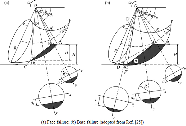
Fig. 2 3D ��horn-shape�� failure mechanisms:
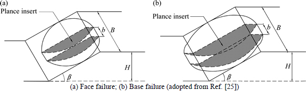
Fig. 3 3D failure mechanisms with finite width B:
 (8)
(8)
where the superscript ��curve�� denotes the work rates for the curvilinear cone at the two ends of the mechanism and the superscript ��plane�� relates to the work rates for the plane insert in the center of the mechanism. The work rates of  and Dplane for the plane insert can be found in the references of CHEN and LIU [27] and MICHALOWSKI and YOU [28]. The expressions of
  and Dcurve for the curvilinear cone are given in the following for 3D face-failure and 3D base-failure mechanisms, respectively.
For 3D face-failure mechanism (Fig. 2(a)), the rotating block has a similar shape to that of 3D toe-failure mechanism, but with a smaller height H ��. The 3D toe-failure mechanism is a special case of 3D face-failure mechanism when H��=H. Hence, the rate of work done by soil weight and internal energy dissipation Dcurve in MICHALOWSKI and DRESCHER [24] with H replaced by H �� can be used for the 3D face-failure mechanism. In conjunction with the equivalent strength parameters (c'and ) from the nonlinear failure criterion, the expressions of and Dcurve can be derived as

 (9)
(9)


 (10)
(10)
where variables a, d1 and angle qB can be obtained from the geometrical and trigonometric relations in Fig. 2, as shown
 (11)
(11)
 (12)
(12)
 (13)
(13)
 (14)
(14)
For the 3D base-failure mechanism, the geometry of failure surface is determined by an added parameter, angle �¡�, as shown in Fig. 2(b). The 3D toe-failure mechanism is also a special case of 3D base-failure mechanism when �¡� equals the inclination angle ��. However, the rate of work done by soil weight and internal energy dissipation in the portion of rotating block below the toe must be counted into the 3D base-failure mechanism. Based on the equivalent strength parameters c�� and  the expressions of and Dcurve for the 3D base-failure mechanism are derived

 (15)
(15)


 (16)
(16)
where the expressions of variable a, angle qB and A' are the same as those for face-failure mechanism. The variables d2, e and angle qC are given as
 (17)
(17)
 (18)
(18)
 (19)
(19)
For details of the procedure and notation, see Refs. [24-25]. It should be noted that the parameter c�� in above expressions is a function of determined by Eq. (3).
2.4 Optimization procedure
In order to obtain the least upper bound to N=gH/c0, an optimization method proposed by CHEN [29] is used here. In the optimization procedure, the global minimum will be found until the band widths of search variables become less than predefined values. From the presented analysis, the parameters st and c0 are found to be not independent. Their combination in a ratio of c0/st affects the stability number. Hence, the generalized coefficient of c0/st is adopted in the optimization procedure, as presented by LI [19] and DENG et al [23].
For a slope with given values (e.g., inclination angle b, nonlinear parameters m and c0/st, and relative width B/H), independent variables in the optimization process include angles q0 and qh, ratio of  relative width of the plane insert b/H, ratio n=H��/H for the 3D face-failure mechanism or angle �¡�for the 3D base-failure mechanism, and one additional variable
  In the search for the minimum value of gH/c0, the optimization procedure is performed until the band widths become less than 0.01�� for angles q0, qh, �¡�and and 0.001 for ratios of n and b/H. The type of corresponding critical failure mechanism can be determined by the critical values of n or �¡�: n<1 for face failure; �¡�<�� for base failure; and n =1 or �¡�=b for toe failure.
3 Results and discussions
Based on the LA method for stability analysis of 3D slopes, numerous calculations were carried out to obtain the least upper bounds to the stability numbers and the corresponding critical slip surfaces. In the calculations, the ratio of c0/st varies from 0.1 to 2.0 and the parameter m is from 1.2 to 2.5. The ratio of width to height B/H is selected as 0.5, 0.8, 1.0, 2.0 and 5.0. The calculated results are presented in the form of charts and tables. The presented results could demonstrate the sensitivity of the slope stability to the nonlinear parameters (c0/st and m) and geometrical constraint B/H. The 3D critical slip surfaces will be also investigated to assess these effects on the type of failure mechanism and the geometry of critical slip surface.
3.1 Effects of ratio c0/st
In Figs. 4-7, the stability numbers N=gH/c0 are shown as a function of c0/st for four slopes (b=30��, 45��, 60��, and 75��) with various values of m and B/H. The curves in each chart are presented with different relative widths: B/H=0.5, 0.8, 1.0, 2.0 and 5.0. The lowest curve marked by ��2D�� represents the stability numbers for the plane-strain log-spiral mechanism. From Figs. 4-7, it is clear that the stability number gH/c0 increases as the ratio of c0/st increases. The increase in the stability numbers is more significant with decreasing values of m, B/H and b. For example, when c0/st varies from 0.1 to 2.0, for a certain narrow slope (m=2.0 and B/H=2.0) with b=60��, the increase in the stability number is 172%; while, for the same slope with b = 45��, this mentioned increase will be as high as 302%. Compared with the stability numbers derived from 2D plane-strain analysis, the stability numbers of 3D slopes become more sensitive to the variation in the values of c0/st. It should be noted that the variation of the stability numbers with the increasing c0/st will change to be linear as m increases, as shown in Figs. 4(b)-7(b).

Fig. 4 Effect of c0/st on stability number and type of failure mechanism (b=30��):
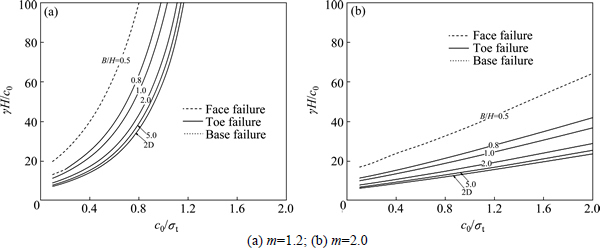
Fig. 5 Effect of c0/st on stability number and type of failure mechanism (b=45��):
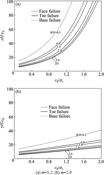
Fig. 6 Effect of c0/st on the stability number and type of failure mechanism (b=60��):
From Figs. 4-7, it can also be found that the type of failure mechanism for gentle slopes (b=30��) is significantly influenced by the ratio of c0/st. For gentle slopes (b=30��) with B/H��1.0, as c0/st increases, the type of failure mechanism changes gradually from face failure to toe failure. This phenomenon is more obvious for slopes with larger values of m. When the relative width B/H is larger than 1.0, the failure mechanism transforms from base failure to toe failure with increasing c0/st. However, once the inclination angle b is larger than 45��,the type of failure mechanism will not be changed. In this situation, the toe-failure mechanism yields the critical value of gH/c0, except for the case B/H=0.5.
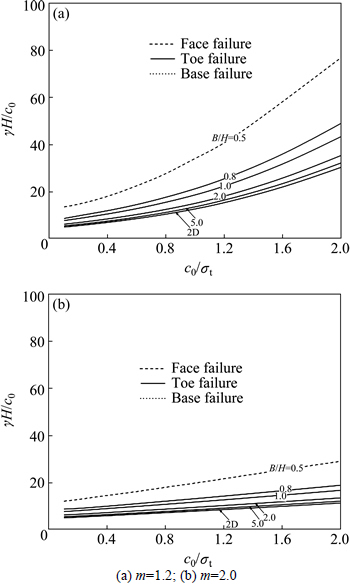
Fig. 7 Effect of c0/st on stability number and type of failure mechanism (b=75��):
To demonstrate the effect of c0/st on the 3D critical slip surface, Figs. 8 and 9 illustrate the 3D critical slip surfaces for slopes (b=30�� and 75�� ) with B/H=5.0. The nonlinear parameter m is adopted as a constant value of 1.6. As shown in Figs. 8 and 9, the 3D slip surface tends to be shallower with increasing c0/st. It can also be found that the 3D effect of critical slip surface becomes less pronounced as c0/st increases.
3.2 Effects of parameter m
Figures 10-13 present the stability numbers N=gH/c0 as a function of m. It is seen that the stability number gH/c0 decreases with increasing m. However, for the case c0/st=0.2 in Figs. 10(a)-13(a), the parameter m is found to have little effect on the stability number. Besides, it can be observed that the decrease in the stability numbers with increasing m will be pronounced for gentle slopes constrained to a narrow width. The 3D solutions for slope stability appear to be more sensitive to the variations in m than the 2D solutions.
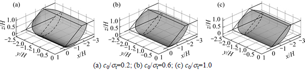
Fig. 8 Effect of c0/st on 3D critical slip surfaces (b=30��):
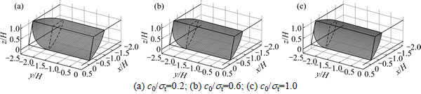
Fig. 9 Effect of c0/st on 3D critical slip surfaces (b=75��):
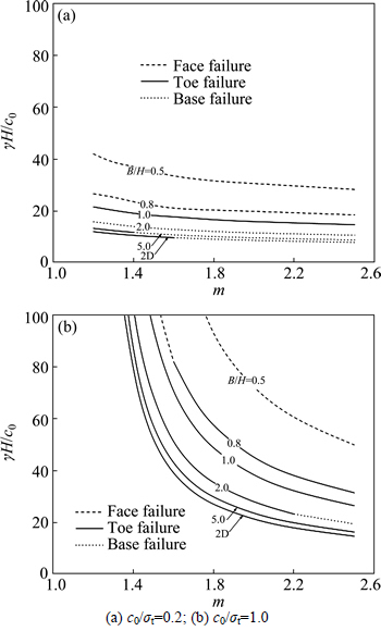
Fig. 10 Effect of m on stability number and type of failure mechanism (b=30��):
The effect of m on the type of 3D failure mechanism is also limited to slopes with b=30��, as shown in Fig. 10. For gentle slopes with B/H<1.0, the 3D failure mechanism changes from face failure to toe failure with increasing m, especially for the cases with larger c0/st. When B/H is larger than 1.0, the 3D failure mechanism tends to change from toe failure to base failure with increasing m, especially for slopes with smaller c0/st.

Fig. 11 Effect of m on stability number and type of failure mechanism (b=45��):
Figures 14 and 15 demonstrate the effect of m on the geometry of the 3D critical slip surface for two slopes with B/H=5.0 and c0/st=1.0. As m increases, a deeper slip surface with more pronounced 3D effect yields the critical value of gH/c0.
It can be concluded that both of the effects of c0/st and m on the stability numbers gH/c0 become significant with decreasing slope width and inclination angle. Compared with the 2D solutions, the 3D solutions are more sensitive to the values of c0/st and m. This indicates the importance of considering the nonlinear failure criterion when conducting the stability analysis of 3D slopes. Furthermore, the type of 3D failure mechanism is significantly influenced by c0/st and m, but limited to slopes with small inclination angles. For the same slope geometry, the 3D effect of the critical slip surface will be more pronounced for slopes with smaller values of c0/st or larger values of m. Therefore, the nonlinear parameters should be well considered and accurately measured in the actual slope engineering, especially for gentle slopes constrained to a narrow width.
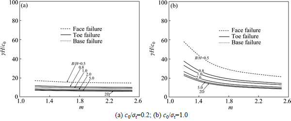
Fig. 12 Effect of m on the stability number and type of failure mechanism (b=60��):

Fig. 13 Effect of m on stability number and type of failure mechanism (b=75��):

Fig. 14 Effect of m on 3D critical slip surfaces (b=30��):
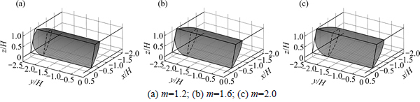
Fig. 15 Effect of m on 3D critical slip surfaces (b=75��):
3.3 Effects of relative width B/H
Table 1 presents the relative differences in stability numbers N=gH/c0 between the 2D and 3D results (B/H=1.0, 2.0, 5.0 and 10.0) for two slopes with b=30�� and 75��. The relative difference d=(N3D-N2D)/N2D��100% is used to show the effect of geometrical constraint B/H on the slope stability. As expected, the relative difference d decreases as B/H increases. The difference can exceed 40% when the slope is constrained to a narrow width of B/H=1.0. However, once the width of the slope reaches B/H=10.0, the relative difference d will be less than 5%. Therefore, the 2D plane-strain analysis is appropriate for the stability of 3D slopes with large widths (B/H��10.0).
From Figs. 4-7 and 10-13, it can be seen that the relative width B/H has significant effect on the type of 3D failure mechanism. To further investigate the effect of B/H on the geometry of 3D slip surface, Figs. 16 and 17 show the 3D critical slip surfaces of two slopes with B/H=0.8, 1.0 and 2.0. The nonlinear parameters of the soil are assumed to be c0/st=0.4 and m=2.0. As expected, the 3D effect of the critical slip surface becomes less obvious with B/H increasing, but the 3D slip surface turns to be deeper.
Table 1 Relative differences between 2D and 3D stability numbers

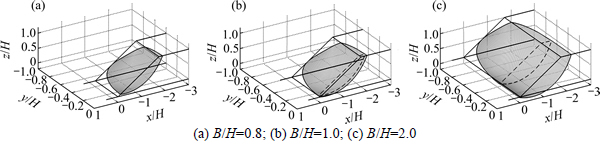
Fig. 16 Effect of B/H on 3D critical slip surfaces (b=30��):
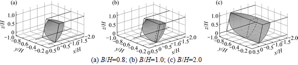
Fig. 17 Effect of B/H on 3D critical slip surfaces (b=75��):
4 Conclusions
1) The stability number gH/c0 increases as the ratio of c0/st increases, but decreases with the parameter m increasing. The effects of c0/st and m on the stability numbers will be more significant with decreasing slope width and inclination angle. Compared with the 2D solutions, the 3D solutions are more sensitive to the values of c0/st and m.
2) The type of the 3D failure mechanism is significantly influenced by c0/st and m, but limited to slopes with small inclination angles. For the same slope geometry, the 3D effect of the critical slip surface is more pronounced for slopes with bigger m or smaller c0/st.
3) For the evaluations of the safety of slopes in soils with the nonlinear failure criterion, the 2D plane-strain solutions can be appropriately used when the ratio of width to height B/H exceeds 10.0.
References
[1] PENMAN A. Shear characteristics of saturated silt measured in triaxial compression [J]. G��otechnique, 1953, 3(8): 312-328.
[2] BISHOP A W, WEBB D L, LEWIN P I. Undisturbed samples of London clay from the Ashford Common shaft: Strength-effective normal stress relationship [J]. G��otechnique, 1965, 15(1): 1-31.
[3] PONCE V M, BELL J M. Shear strength of sand at extremely low pressures [J]. Journal of the Soil Mechanics and Foundations Division, 1971, 97(4): 625-637.
[4] LEFEBVRE G. Strength and slope stability in Canadian soft clay deposits [J]. Canadian Geotechnical Journal, 1981, 18(3): 420-442.
[5] MAKSIMOVIC M. Nonlinear failure envelope for soils [J]. Journal of Geotechnical Engineering, ASCE, 1989, 115(4): 581-586.
[6] de MELLO V F B. Reflections on design decisions of practical significance to embankment dams-17th Rankine lecture [J]. G��otechnique, 1977, 27: 281-354.
[7] CHARLES J A. An appraisal of the influence of a curved failure envelope on slope stability [J]. G��otechnique, 1982, 32(4): 389-392.
[8] ZHANG X J, CHEN W F. Stability analysis of slopes with general nonlinear failure criterion [J]. International Journal for Numerical and Analytical Methods in Geomechanics, 1987, 11(1): 33-50.
[9] BAKER R. Nonlinear Mohr envelopes based on triaxial data [J]. Journal of Geotechnical and Geoenvironmental Engineering, ASCE, 2004, 130(5): 498�C506.
[10] TAYLOR R K. Properties of mining wastes with respect to foundations [M]// Foundation Engineering in Difficult Ground. London: Newnes-Butterworth, 1978: 175-203.
[11] CHARLES J A, SOARES M M. The stability of slopes in soils with nonlinear failure envelopes [J]. Canadian Geotechnical Journal, 1984, 21(3): 397�C406.
[12] PERRY J. A technique for defining non-linear shear strength envelopes and their incorporation in a slope stability method of analysis [J]. Quarterly Journal of Engineering Geology and Hydrogeology, 1994, 27: 231-241.
[13] DRESCHER A, CHRISTOPOULOS C. Limit analysis slope stability with nonlinear yield condition [J]. International Journal for Numerical and Analytical Methods in Geomechanics, 1988, 12(5): 341-345.
[14] YANG Xiao-li, YIN Jian-hua. Slope stability analysis with nonlinear failure criterion [J]. Journal of Engineering Mechanics, ASCE, 2004, 130(3): 267-273.
[15] YANG Xiao-li, HUANG Fu. Slope stability analysis considering joined influences of nonlinearity and dilation [J]. Journal of Central South University of Technology, 2009, 16: 292-296.
[16] ZHAO Lian-heng, LI Liang, YANG Feng, LUO Qiang, LIU xiang. Upper bound analysis of slope stability with nonlinear failure criterion based on strength reduction technique [J]. Journal of Central South University of Technology, 2010, 17: 836-844.
[17] ZHAO Lian-heng, YANG Feng, ZHANG Ying-bin, DAN Han-sheng, LIU Wei-zheng. Effects of shear strength reduction strategies on safety factor of homogeneous slope based on a general nonlinear failure criterion [J]. Computers and Geotechnics, 2015, 63: 215-228.
[18] BAKER R. Variational slope stability analysis of materials with non-linear failure criterion [J]. Electronic Journal of Geotechnical Engineering, 2005, 10: 19.
[19] LI X. Finite element analysis of slope stability using a nonlinear failure criterion [J]. Computers and Geotechnics, 2007, 34(3): 127- 136.
[20] LI Da-zhong, CHENG Yung-ming. Lower bound limit analysis using nonlinear failure criteria [J]. Procedia Earth and Planetary Science, 2012, 5: 170-174.
[21] YANG Xin-guang, CHI Shi-chun. Upper bound finite element analysis of slope stability using a nonlinear failure criterion [J]. Computers and Geotechnics, 2013, 54(10): 185-191.
[22] JIANG J C, BAKER R, YAMAGAMI T. The effect of strength envelope nonlinearity on slope stability computations [J]. Canadian Geotechnical Journal, 2003, 40(2): 308-325.
[23] DENG Dong-ping, ZHAO Lian-heng, LI Liang. Limit equilibrium slope stability analysis using the nonlinear strength failure criterion [OL/OJ]. Canadian Geotechnical Journal, 2014, 10.1139/cgj-2014- 0111.
[24] MICHALOWSKI R L, DRESCHER A. Three-dimensional stability of slopes and excavations [J]. G��otechnique, 2009, 59(10): 839-850.
[25] GAO Yu-feng, ZHANG Fei, LEI Guo-hui, LI Da-yong. An extended limit analysis of three-dimensional slope stability [J]. G��otechnique, 2013, 63(6): 518-524.
[26] CHEN W F. Limit analysis and soil plasticity [M]. Amsterdam: Elsevier, 1975.
[27] CHEN W F, LIU X L. Limit analysis in soil mechanics [M]. Amsterdam: Elsevier, 1990.
[28] MICHALOWSKI R L, YOU L Z. Displacements of reinforced slopes subjected to seismic loads [J]. Journal of Geotechnical and Geoenvironmental Engineering, ASCE, 2000, 126(8): 685-694.
[29] CHEN Zu-yu. Random trials used in determining global minimum factors of safety of slopes [J]. Canadian Geotechnical Journal, 1992, 29(2): 225-233.
(Edited by DENG L��-xiang)
Foundation item: Project(201501035-03) supported by the Public Service Sector R&D Project of Ministry of Water Resource of China; Project (2015CB057901) supported by Basic Research Program of China; Projects(51278382, 51479050, 51508160) supported by the National Natural Science Foundation of China; Project(B13024) supported by the 111 Project; Projects(2014B06814, B15020060, 2014B33414) supported by the Fundamental Research Funds for the Central Universities, China;Project(YK913004) supported by the Open Foundation of Key Laboratory of Failure Mechanism and Safety Control Techniques of Earth-rock Dam of the Ministry of Water Resources, China; Project(KYZZ_0143) supported by the Graduate Education Innovation Project of Jiangsu Province of China
Received date: 2015-05-26; Accepted date: 2015-10-26
Corresponding author: GAO Yu-feng, Professor, PhD;Tel: +86-25-83787287;E mail: yfgao66@163.com

