Non-linear performance analysis and voltage control of MFC based on feedforward fuzzy logic PID strategy
来源期刊:中南大学学报(英文版)2019年第12期
论文作者:安爱民 罗青竹 张浩琛 孟凡成
文章页码:3359 - 3371
Key words:microbial fuel cell; feedforward fuzzy logic PID; nonlinear performance analysis; output voltage tracking
Abstract: Microbial fuel cell (MFC) is a kind of promising clean power supply energy equipment, but serious nonlinearities and disturbances exist when the MFC runs, and it is an important topic to guarantee that the output voltage reaches the setting value quickly and smoothly. Regulating the feeding flow is an effective way to achieve this goal, and especially, the satisfactory results can be achieved by regulating anode feeding flow. In this work, a feedforward fuzzy logic PID algorithm is proposed. The fuzzy logic system is introduced to deal with the non-linear dynamics of MFC, and corresponding PID parameters are calculated according to defuzzification. The magnitude value of the current density is used to simulate the value of the external load. The simulation results indicate that the MFC output voltage can track the setting value quickly and smoothly with the proposed feedforward fuzzy logic PID algorithm. The proposed algorithm is more efficient and robust with respect to anti-disturbance performance and tracking accuracy than other three control methods.
Cite this article as: LUO Qing-zhu, AN Ai-min, ZHANG Hao-chen, MENG Fan-cheng. Non-linear performance analysis and voltage control of MFC based on feedforward fuzzy logic PID strategy [J]. Journal of Central South University, 2019, 26(12): 3359-3371. DOI: https://doi.org/10.1007/s11771-019-4259-4.

J. Cent. South Univ. (2019) 26: 3359-3371
DOI: https://doi.org/10.1007/s11771-019-4259-4

LUO Qing-zhu(罗青竹)1, 3, AN Ai-min(安爱民)1, 2, 3,ZHANG Hao-chen(张浩琛)1, 2, 3, MENG Fan-cheng(孟凡成)1, 3
1. College of Electrical and Information Engineering, Lanzhou University of Technology,Lanzhou 730050, China;
2. Key Laboratory of Gansu Advanced Control for Industrial Processes, Lanzhou 730050, China;
3. National Demonstrain Center for Experimental Electrical and Control Engineering Education, Lanzhou University of Technology, Lanzhou 730050, China
 Central South University Press and Springer-Verlag GmbH Germany, part of Springer Nature 2019
Abstract: Microbial fuel cell (MFC) is a kind of promising clean power supply energy equipment, but serious nonlinearities and disturbances exist when the MFC runs, and it is an important topic to guarantee that the output voltage reaches the setting value quickly and smoothly. Regulating the feeding flow is an effective way to achieve this goal, and especially, the satisfactory results can be achieved by regulating anode feeding flow. In this work, a feedforward fuzzy logic PID algorithm is proposed. The fuzzy logic system is introduced to deal with the non-linear dynamics of MFC, and corresponding PID parameters are calculated according to defuzzification. The magnitude value of the current density is used to simulate the value of the external load. The simulation results indicate that the MFC output voltage can track the setting value quickly and smoothly with the proposed feedforward fuzzy logic PID algorithm. The proposed algorithm is more efficient and robust with respect to anti-disturbance performance and tracking accuracy than other three control methods.
Key words: microbial fuel cell; feedforward fuzzy logic PID; nonlinear performance analysis; output voltage tracking
Cite this article as: LUO Qing-zhu, AN Ai-min, ZHANG Hao-chen, MENG Fan-cheng. Non-linear performance analysis and voltage control of MFC based on feedforward fuzzy logic PID strategy [J]. Journal of Central South University, 2019, 26(12): 3359-3371. DOI: https://doi.org/10.1007/s11771-019-4259-4.
1 Introduction
The energy shortage of the world is one of the most grim issues that is urgently needed to be resolved by using some sophisticated solutions. Currently, fossil energy accounts for more than 86% of global energy consumption according to statistics from the International Energy Agency (IEA). Particularly, 95% of the dependence on fossil fuel is in transportation industry [1, 2]. Therefore, diversifying the energy utilization mode is a major research content to alleviate the damage caused by fossil energy to the environment. Microbial fuel cell is an electrochemical equipment that can directly convert chemical energy into electrical power by the process of microbial metabolism, and it is a new kind of biomass energy utilizing electrogenic microorganism to get electrical power [3]. Microbial fuel cell (MFC) exhibits many attractive advantages compared with the conventional chemical fuel cell, such as wide range of raw materials, mild reaction condition, and high efficiency. Firstly, MFC essentially uses the metabolism of exoelectrogenic microorganisms to release electrons and then the electrons pass through external load to realize utilization of electric energy. Carbon sources available to various exoelectrogenic microorganisms varying greatly (organic acids, alcohols, sugars, amino acids and acetate and more). This characteristic allows MFC to use a variety of raw materials for metabolism. Secondly, the temperature required for MFC in operation is relatively mild. BOGHANI et al [4] measured the power curve of MFC at 30 °C, almost room temperature. Lastly, the conversion efficiency of electric energy is comparatively effective, and the coulombic efficiency of MFC can reach 63.4% in alkaline environment [5].
At present, the researches on MFC contain the optimization of battery configuration, electrode material research, electron transfer mechanism, bacterial population selection, catalyst reaction substrate and voltage output control methods. LOGAN et al [6] studied the configuration of MFC and the improvement of electrode materials. The research achievements show that brush anode of multi-pore structure and high superficial area can produce high power densities. DI LORENZO et al [7] found that the output current density of single chamber MFC increased as the superficial area increase of the anode electrode. REN et al [8] discovered that the MFC with micro size structure has higher current and power density. CHENG et al [9] researched the cathode MFC of the air, and found that the output voltage of the system increases with the increase of anode substrate concentration and conductivity of cathode solution. BOROLE et al [10] found that increasing the amount of bacteria in anode supply can raise the system output voltage. In terms of voltage output optimization control, BOGHANI et al [11] gave control of MFC’s voltage based on a gain scheduling control strategy, providing for a basis control of MFC stacks, and optimizing energy harvesting systems and low-power electronics powered by MFC. BOGHANI et al [12] employed sampled-time control of a microbial fuel cell stack, and the performance of the sampled-time controller is satisfactory because it can maintain a consistent MFC voltage suppressing variations caused by electrical loads, ambient temperature and substrate depletion. All these studies have acquired many achievements, but it is still necessary to guarantee output voltage stable and reliable when MFC is used as a power source, and the issue is an important technical challenge that need to address. So, the research on voltage output optimization control is still significant. On the whole, it is indispensable to study the output optimization of MFC from control strategy.
Some works report that PID method has been used to manipulate the output voltage of MFC, but the effectiveness of PID method is unsatisfactory when the non-linear property of the controlled object is too strong. So for the higher order system, there are some modified algorithms for PID strategy. For the conventional fuzzy logic PID (CFPID), its basic principle is to introduce the difference between the setting value and the feedback value of the control system and its first derivative to the input of the fuzzy logic controller [13]. To dynamically adjust the value of the PID parameters according to the different input conditions after the fuzzy reasoning, when this method is applied to the output voltage optimization control of MFC in small voltage setting value, the CFPID method can also achieve a certain voltage tracking effects since the biochemical reaction inside MFC is relatively gentle for MFC [14]. But when the voltage setting value is high, the control ability of output voltage becomes worse due to intense chemical reaction inside MFC, and the CFPID method cannot make adaptive adjustments to control parameters based on this special case. In order to make specific optimization of control parameters at high voltage setting, the feedforward fuzzy logic PID control introduces the voltage setting value to the input of the fuzzy logic controller. The feedforward fuzzy logic PID (FFPID) method is a suitable way to describe the relationships between system variables for better robustness, adaptability and better fault tolerance using fuzzy control rules. In this study, the fuzzy logic control rules are designed to adjust three parameters of the PID, which make the output voltage of the MFC fast and stable in accordance with the voltage setting value. Simultaneously, the FFPID controller can restrain the disturbance and ensure that the voltage output does not fluctuate greatly to protect the electric loads when external interference exists.
The structure of this paper is formed as follows: description of mathematical model are introduced in Section 2; non-linear performance analysis, design of feedforward fuzzy logic PID and its simulation results are presented in Section 3; conclusions are given in Section 4.
2 Fundamental mechanism of MFC
2.1 Basic working principle
Many types of MFC exist according to the different principles of power generation, but heterotrophic MFC is the most widely used for anaerobic bacteria or facultative microorganisms to extract electrons by combustion of organic matter under anaerobic conditions and to generate electricity power by electron transfer, and it is also the most commonly applied MFC reactor. Dual-compartment structural MFC is shown in Figure 1.
Anode chamber needs to maintain anaerobic environment (Initially, eliminating residual oxygen by inletting nitrogen in acetate solution). The acetate substrate is oxidized by the catalysis of the bacteria in the anode compartment. The anode electrode provides a carrier for the attachment of the electrogenic microorganism and conducts electrons. The generated electrons are transferred to the anode electrode through an electron carrier located on the extracellular membrane and then to the negative electrode via an external load. The basic requirements of the anode electrode material are corrosion-resistant, high conductivity, high porosity, large specific surface area and hard to plug. WANG et al [15], and LI et al [16] showed that the graphite felt is utilized for electrode material for high conductivity and large specific surface area, graphite felt electrode material is beneficial to increase the electrode capacitance and can effectively improve the anode performance of MFC. LAI et al [17] found that anode modified by polyaniline can effectively improve the power generation efficiency of MFC.
The aerobic environment is achieved in cathode chamber by injecting air-saturated water, and the cathode electrode placed in the cathode solution. Dissolved oxygen in solution can be the electron acceptor by aeration, and other soluble electron acceptors can achieve the same performance. Some noble metals can be used as catalysts to accelerate cathode reaction rate for MFCs due to their excellent stability [18]. The cathode uses the same electrode material with anode electrode, but the graphite felt used as cathode electrode is coated with powdered platinum powder in order to improve the effect of reduction reaction.
The proton exchange membrane isolates the anode compartment from the cathode chamber and allows hydrogen ions transfer from the anode to the cathode, and the dissolved oxygen and the transferred electrons combine to produce water in the cathode chamber.
In addition, there are gas storage tanks, pipes, valves, pumps and other feeding auxiliary equipments.
2.2 Mathematical model
There are many different expressions of the mathematical model of MFC. The steady-state MFC 1D model study the thermal coupling, charge and proton transfer process and biofilm formation in MFC electrochemical process, which is similar to the research of chemical fuel cell [19]. PINTO [20] constructed a two-population bio-electrochemical model of MFC, which describes the formation and retention of the biofilm in the anode compartment by using ordinary differential equations[20]. In this paper, the acetate in the substrate solution is oxidized by electrogenic microorganism in the anode chamber and releases electrons as described in Eq. (C1). The anode chamber biochemical kinetics can be simulated using anaerobic digestion model No. 1 for the anode chamber like MFC operating in an anaerobic or anoxic environment [21, 22]. The reaction rate is expressed in the same manner as the Butler-Volmer expression in electrochemical cell. MFC also uses this formula to represent the chemical reaction rate. Unlike traditional fuel cells, such as hydrogen oxygen fuel cell, using pure fuel as the oxidized substance, MFC can oxidize a variety of inorganic chemicals as raw materials for microbial metabolism, which causes the cationic group M+ to pass through the proton exchange membrane, not just the protons, during mass transport. Based on biochemical reaction, Butler-Volmer equation and material balance and charge balance equation, the chamber MFC model is established by ZENG et al [23], and the expression of anode reaction rate is as Eq. (1) based on the model:
 =
= (1a)
(1a)
 (1b)
(1b)
The depletion of dissolved oxygen in the cathode chamber is presented as Eq. (2a), analogously, the electrochemical reaction rate of cathode chamber is also expressed in Butler-Volmer expression as Eq. (2b):
 =
= (2a)
(2a)
 (2b)
(2b)
It is assumed that a continuously stirred tank reactor can be applied in both the anode and cathode compartment [24]. The reaction rate in solution can be considered as equality to the reaction rate on the face of the electrode because the mass transfer processes are assumed to be faster than the biochemical and redox reactions. In addition, it is assumed that carbon dioxide and acetate do not pass through the proton exchange membrane. Consequently, the mass balance equations of acetate, dissolved CO2, hydrogen ions and biomass in the anode chamber are presented in Eqs. (3)-(6), respectively:
 (3)
(3)
 (4)
(4)
 (5)
(5)
 (6)
(6)
where a stands for the anode; in represents the feeding flow.
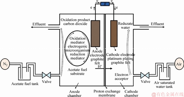
Figure 1 Schematic diagram of MFC
Assuming that only hydrogen ions are transported through the proton exchange membrane, the M+ ion group will not participate in the chemical reaction in the cathode chamber. The mass balances equation of dissolved O2, hydroxyl, and cations M+ are expressed by Eqs. (7)-(9):
 (7)
(7)
 (8)
(8)
 (9)
(9)
where the subscript c means the cathode; NM indicates the flux of M+ ions from the anode chamber to the cathode chamber. The expression of NM is as described:
 (10)
(10)
where 3600 is the factor of unit conversion; Jcell is cell current density, and is related to feeding flow and the load. The current density will also vary with changeable load.
The charge balance equations of the anode and the cathode are expressed by Eqs. (11)-(12), respectively:
 (11)
(11)
 (12)
(12)
It is assumed that the ohmic potential drop can be ignored, and MFC’s internal resistance is determined only by the substrate solution and membrane. Consequently, the voltage Ucell is calculated as Eq. (13):
 (13)
(13)
A detailed description of the parameters in Table 1 is shown in Ref. [23]. It is noted that the first six parameters are estimated values of acetate MFC, the rest of the parameters are referenced according to Ref. [23].
Table 1 Model parameters of MFC

The above MFC mathematical model described by the differential equations is not intuitive, so Figure 2 gives a simplified diagram of the MFC structure in a graphical manner in order to present the relationship between inputs and outputs of the controlled object in a clearer and more introductory manner. In Figure 2, there are three modules: the material balance equation of the anode chamber, cathode chamber described above, and the charge balance equation. Each module consists of the differential equations. Reaction rate of anode and cathode chamber (r1, r2) is intermediate variable connecting the material balance module and the charge balance module. Simultaneously, the charge balance module feeds back the overpotential value (ηa , ηa) to the material balance module. It can be seen that the inputs of the controlled object are the anode feeding flow flux (Qa), the cathode feeding flow flux (Qc), and the current density value (Jcell); the outputs are the voltage (Vcell) and power density (Pcell) of the MFC. Next, the relationship between inputs and outputs is analyzed to determine the appropriate control variable and controlled variable and use some input variables to simulate the actual physical quantities of MFC.
3 Dynamics analysis simulation
3.1 Input-output relationship analysis of MFC
Qa and Qc are the inputs of the MFC system according to Eqs. (3)-(9). Since the value of current density is closely related to the size of external load, the current density plays a role in simulating the load changes in this paper. But in accordance with the existing research, the major impact on the MFC output voltage is the anode feeding flow flux and solution conductivity, and the conductivity of solution can be improved by adding electrolyte [25]. So it is firstly assumed that the external load is constant (i.e., the current density remains unchanged). The dynamic characteristics are analyzed after constructing the SIMULINK model in MATLAB 2016a. The output voltage curves are shown in Figure 3 when the anode feeding flux with different constants is applied. It can be observed that the output voltage tends to be stable when the external load remains constant. However, at the 1500th s, the cathode feeding flow flux increases from 1.11×10⁻³ to 1.61×10⁻³ m3/h. It can be seen from three partial enlarged details that: the range of voltage change is very limited by changing cathode feeding flux; voltage output value remains unchanged during the simulation time. The power density curve is similar to Figure 3.
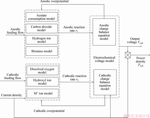
Figure 2 Dynamic structure diagram of MFC
In order to test and verify the effect of cathode feeding flow on output voltage again, Figure 4 shows the response curve of cathode feeding flux to output voltage when the anode feeding flow and current density are constant. The voltage steady-state value difference is very small after the output voltage curve is stabilized when the cathode feeding flow is given three different orders of magnitude. The reason is that the utilization of dissolved oxygen reaches saturation when the cathode chamber uses dissolved oxygen as electron acceptor. This rule is applicable when many different sets of anode feeding flow and current densities have been tested, so the cathode feeding flow can be considered as saturation invariant (1.11×10⁻³ m3/h) in later research.
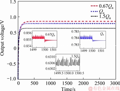
Figure 3 Output voltage with different anode feeding flux

Figure 4 Output voltage with different cathode feeding flux
Figure 5 shows the non-linear relationship between the current density and the output voltage at the different anode feeding flow flux. The output voltage decreases with the increase of the current density. Particularly, it can be seen from the 1.5Qa curve that there are three following stages of the whole process:
1) When the current density is small (less than 1 A/m2), the electron transfer between electrode and redox reaction is too slow, resulting in that electrode potential deviates from the equilibrium potential, and polarization loss is the principal reason for voltage drop.
2) When the current density is moderate (between 1 and 6 A/m2), the curve changes smoothly, and the principal reason for the decrease in voltage at this stage is ohmic losses.
3) When the current density is large (more than 6 A/m2), reactants concentration will decrease in liquid layer near the electrode and electrolyte interface, and concentration of the products increase. Due to the concentration difference, the reactants and products will diffuse to the electrode and the solution, respectively. The voltage drop at this stage is mainly caused by the concentration difference polarization.
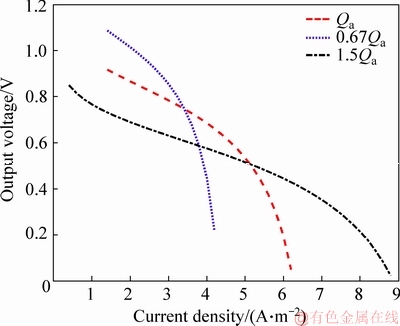
Figure 5 Relationship between current density and output voltage
Figure 6 shows the effect of anode feeding flow on the output voltage at different current densities. There is an optimal anode feeding flow that makes the output voltage maximum. The voltage rises rapidly before the optimal anode feeding flow flux, which is sensitive to the change of anode feeding flow. In practice, the reactants are discharged from the MFC system without involving in the reaction when the anode feeding flow is too large, which is also the reason for the decline of the voltage.

Figure 6 Relationship between anode feeding flow and output voltage
Figure 7 shows the relationship between the current density and power density. Some conclusions can be drawn from the curves that the current density at the maximum power density is exactly the current density value at the end of the ohmic polarization. So the current density should be kept at the end of the ohmic polarization in order to obtain the maximum power output.
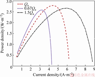
Figure 7 Relationship between current density and power density
According to these characteristics analyzed above, MFC is a non-linear system with multiple inputs and outputs. The anode feeding flow has the most obvious effect on the output voltage, so the anode feeding flow is chosen as the control variable; the cathode feeding flow can be as constant and the current density value simulates the external load. The appropriate controller is essential to make the MFC output track the setting voltage value quickly and stably to provide the stable voltage to the external load.
3.2 FFPID control algorithm for MFC
In this section, firstly, the PID controller is designed to control the anode feeding flow flux. The simulation results demonstrate that PID and CFPID method can achieve a certain control performance, but the response of the system is not satisfactory enough in accuracy, adjustment time and anti-load changes, especially, the actual value deviates from the setting value when the setting value is large. So, the feedforward fuzzy logic PID algorithm is proposed using r(t) as a fuzzy input variable. The schematic diagram of feedforward fuzzy logic PID control is shown in Figure 8.
The inputs of feedforward fuzzy logic controller are voltage setting value r(t) , error e(t), error change rate de(t); the outputs are the variation of three parameters of PID, namely, △KP, △KI, △KD.
 (14)
(14)

 (15)
(15)
where KP0, KI0, KD0 are three initial parameters. For practical engineering problems, the above- mentioned parameters are gradually determined by testing method. V(t)is the actual output voltage. The fuzzy controller facilitates the operator to use natural language for man-machine dialogue, and it is also a non-linear controller with excellent control performance, robustness, adaptability, and better fault tolerance.
Table 2 shows the domain of the input variables of the fuzzy logic controller. The fuzzy domain of r(t) is [0, 1], which is determined by the voltage output range with control simulation experiment. Due to the influence of various polarization phenomena in the initial stage of voltage output, the voltage fluctuation is very large. In order to ensure the completeness of fuzzy logic, the error field is set to [-10, 10]. The system eventually needs to become stable, and the derivative value should gradually change from negative to zero.
Table 3 shows the domain of the output variables of the fuzzy logic controller. The most important work is to determine control rules, and the membership function is a quantitative description of fuzzy concept. The correct membership functions need to be determined firstly when using fuzzy set theory to solve practical problems. The most commonly used membership function is the Gauss type fuzzy distribution as follows:
 (16)
(16)
where a is the mathematical expectation; b is twice the variance.
The inputs use symmetric Gaussian membership functions to realize fuzzification as Figure 9.
Take one of the rules as an example: for KP, if r(t) is NB, e(t) is NB, de(t)/dt is NB, then KP is NB, KI is ZO, KD is ZO.
Input: if r(t) is A′, e(t) is B′ and de(t) is C′.
Premise: if r(t) is A, e(t) is B and de(t) is C, so KP is D.
Conclusion: KP is D′.
Fuzzy implication relationship can be remarked as A×B×C→D. Mamdani fuzzy implication relationship [13] is described as Eq. (17):


 (17)
(17)
 (18)
(18)
In the fuzzy implication relationship above, A,B, C represents the domain of inputs respectively; D represents the domain of KP; represents reasoning operator. After fuzzificating inputs and fuzzy reasoning, the output membership value is calculated as Eq. (19):
 (19)
(19)
Using centroid as a clear value of △KP, the defuzzification is described as Eq. (20):
 (20)
(20)
where CPk is the central value of fuzzy set at the k-th rule. Similarly, △KI and △KD can be calculated.
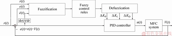
Figure 8 Schematic diagram of feedforward fuzzy logic PID control for MFC
Table 2 Inputs domain
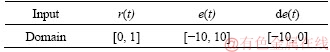
Table 3 Outputs domain


Figure 9 Input fuzzification based on symmetric Gaussian membership funetions
Table 4 lists the fuzzy control rules designed with different voltage set values, errors, and first- order derivatives of errors.
3.3 Simulation analysis
In this subsection, the PID control algorithm, neural network predictive control (NNPC) and conventional fuzzy PID controller are designed to manipulate the anode feeding flow flux. The control performance of the proposed FFPID is compared with neural network predictive control in Ref. [25], and the control effect can be seen as follows:
Figure 10 presents three different voltage settings, namely 0.35, 0.65 and 0.4 V. The simulation results show that the PID controller, NNPC and CFPID can achieve a certain control effect, but the response of the system is not good enough in terms of accuracy, adjustment time, especially when the voltage setting value is high (0.65 V). The voltage output of the NNPC method appears jagged since the biochemical reaction inside the MFC is severe, which is absolutely harmful to the voltage-sensitive load. The output voltage deviates from the setting value far in high voltage setting when CFPID and PID methods are adopted, and the control effect is not ideal. However, FFPID method can track the setting voltage quickly and accurately, and overshoot and steady-state error of the FFPID method are better than those of PID, NNPC and CFPID controllers. The reason is that FFPID takes the voltage setting as the feedforward variable to participate in the decision-making of the PID control parameters, and the PID parameters are adjusted when the voltage setting value is tracked according to the biochemical reaction inside the battery. It is of great significance to improve the tracking error for the load which is sensitive to the output voltage.
Figure 11 shows that the control performance of FFPID on anode feeding flow is more rapid and stable when the voltage setting changes at 500 s and 1500 s compared with PID, NNPC and CFPID. Combined with the information shown in Figure 6,the voltage setting value is abruptly changed at a given moment, since the anode feeding flow has a higher influence rate on the output voltage before the optimum anode feeding flow. It means that smaller anode feeding value changes can cause dramatic changes in the output voltage, so there is not much difference in the steady state value of the anode feeding flow.
Table 4 Fuzzy control rules for MFC after defuzzification
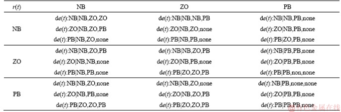

Figure 10 Voltage tracking performance using different control algorithms
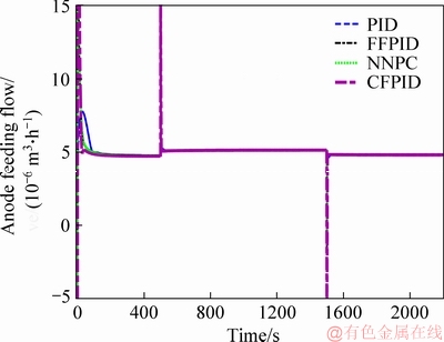
Figure 11 Change of anode feeding flow using different control algorithm
Figure 12 shows the control effects of anode overpotential under different control methods. It can be seen that when FFPID method is used, the change curve of the anode overpotential is quite stable and fast compared with the other three methods in the initial stage of the implementation of the control function. The main reason is that internal polarization phenomenon is more obvious in the initial start-up stage of MFC. The FFPID method can make adaptable change to the three parameters of PID when the voltage setting value is low, so the control of anode overpotential is relatively gentle when using FFPID method.
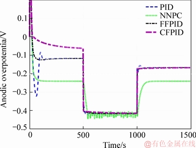
Figure 12 Change of anode overpotential using different control algorithm
In Figure 13, the current density changes abruptly at 500 s and 1500 s to simulate the sudden change of external load in MFC. For the load, it is necessary to keep its voltage steady at a certain value for a long time, and the controller needs to adjust quickly when the load suddenly changes due to various reasons to ensure that the voltage can quickly come back to the setting value, and the effect of output voltage on the load should be as small as possible in the process of adjustment. It can be seen that the curve obtained under the control of FFPID can return the voltage setting after the sudden change of the load, and the voltage transient shock on the load during the adjustment process is smaller than those of other three methods. It will be helpful to ensure the security of the external load.
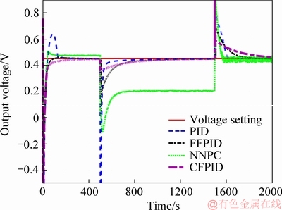
Figure 13 Output voltage change of anti load disturbance using different control algorithms
In order to illustrate the performance of the proposed FFPID, it is assumed that the external load is affected by white noise with 0.0001 W power. Figure 14 shows the performance of the voltage output in the presence of the disturbance. It can be seen that the output voltage fluctuates near the set-point value, but it is finally stable, and can track its set-point when white noise is added to the whole process.
From the analysis of simulation results above, voltage output of MFC has better ability to track the setting value when the feedforward fuzzy logic PID is used, and some satisfactory performance indices can be achieved. The control performance of the feedforward fuzzy logic PID is better than those of PID, NNPC and CFPID regardless of the abrupt interference or the external disturbance in the whole process. The improved PID algorithm achieves the desired control effect.

Figure 14 Voltage output change using different control algorithms with white noise
4 Conclusions
In this paper, the model of MFC is described and the simulation of the output performance is analyzed under the proposed control method in detail. The anode feeding flow is manipulated by the FFPID controller to make the MFC output voltage reach the setting value quickly and smoothly. The simulation results validate that FFPID controller can manipulate the output voltage faster and more stable, and the ability of FFPID method to adjust the internal polarization of MFC is stronger at the initial stage of the control effect compared with other three control methods. When the load changes abruptly or white noise is added in the control process, the output voltage of MFC can still track its setting point quickly and accurately, which solves the problem of stable power supply of MFC for external load. Further research on the control of MFC will focus on considering new control method called economic model predictive control when there are state constraints and economic indicators. It is a rolling time domain optimization algorithm using the economic objective function to obtain the sequence of control variables. The control method involving actual constraints and economic indicators is more in line with the practical application background of MFC.
References
[1] KADIER A, KALIL M S, ABDESHAHIAN P, CHANDRASEKHAR K, MOHAMED A, AZMAN N F, LOGRONO W, SIMAYI Y, HAMID A A. Recent advances and emerging challenges in microbial electrolysis cells (MECs) for microbial production of hydrogen and value-added chemicals [J]. Renewable and Sustainable Energy Reviews, 2016, 61: 501-525.
[2] JAFARY T, DAUD W R W, GHASEMI M, KIM B H, MD JAHIM J, ISMAIL M, LIM S S. Biocathode in microbial electrolysis cell; present status and future prospects [J]. Renewable and Sustainable Energy Reviews, 2015, 47: 23-33.
[3] LOGAN B E, HAMELERS B, ROZENDAL R, SCHRODER U, KELLER J, FREGUIA S, AELTERMAN P, VERSTRAETE W, RABAEY K. Microbial fuel cells: Methodology and technology [J]. Environmental Science & Technology, 2006, 40(17): 5181-5192.
[4] BOGHANI H C, KIM J R, DINSDALE R M, GUWY A J, PREMIER G C. Analysis of the dynamic performance of a microbial fuel cell using a system identification approach [J]. Journal of Power Sources, 2013, 238: 218-226.
[5] LI Xiao-min, CHENG Ka-yu, WONG J W C. Bioelectricity production from food waste leachate using microbial fuel cells: Effect of NaCl and pH [J]. Bioresource Technology, 2013, 149: 452-458.
[6] LOGAN B, CHENG Shao-an, WATSON V, ESTADT G. Graphite fiber brush anodes for increased power production in air-cathode microbial fuel cells [J]. Environmental Science & Technology, 2007, 41(9): 3341-3346.
[7] DI LORENZO M, SCOTT K, CURTIS T P, HEAD I M. Effect of increasing anode surface area on the performance of a single chamber microbial fuel cell [J]. Chemical Engineering Journal, 2010, 156(1): 40-48.
[8] REN H, TORRES C I, PARAMESWARAN P, RITTMANN B E, CHAE J. Improved current and power density with a micro-scale microbial fuel cell due to a small characteristic length [J]. Biosensors and Bioelectronics, 2014, 61: 587-592.
[9] CHENG Shao-an, LOGAN B E. Increasing power generation for scaling up single-chamber air cathode microbial fuel cells [J]. Bioresource Technology, 2011, 102(6): 4468-4473.
[10] BOROLE A P, HAMILTON C Y, VISHNIVETSKAYA T, LEAK D, ANDRAS C. Improving power production in acetate-fed microbial fuel cells via enrichment of exoelectrogenic organisms in flow-through systems [J]. Biochemical Engineering Journal, 2009, 48(1): 71-80.
[11] BOGHANI H C, MICHIE I, DINSDALE R M, GUWY A J, PREMIER G C. Control of microbial fuel cell voltage using a gain scheduling control strategy [J]. Journal of Power Sources, 2016, 322: 106-115.
[12] BOGHANI H C, DINSDALE R M, GUWY A J, PREMIER G C. Sampled-time control of a microbial fuel cell stack [J]. Journal of Power Sources, 2017, 356: 338-347.
[13] LI Hui-min, WANG Xiao-bo, SONG Shang-bin, LI Hao. Vehicle control strategies analysis based on PID and fuzzy logic control [J]. Procedia Engineering, 2016, 137: 234-243.
[14] YAN Min-xiu, FAN Li-ping. Constant voltage output in two-chanber microbial fuel cell under fuzzy PID control [J]. International Journal of Electrochemical Science, 2013, 8: 3321-3332.
[15] WANG Guan-wen, FENG Chun-hua. Electrochemical polymerization of hydroquinone on graphite felt as a pseudocapacitive material for application in a microbial fuel cell [J]. Polymers, 2017, 9(12): 220.
[16] LI Jing, LI Jie, LAI Yan-qing, SONG Hai-sheng, ZHANG Zhi-an, LIU Ye-xiang. Influence of KOH activation techniques on pore structure and electrochemical property of carbon electrode materials [J]. Journal of Central South University of Technology, 2006, 13(4): 360-366.
[17] LAI Bin, WANG Peng, LI Hao-ran, DU Zhu-wei, WANG Lijuan, BI Si-chao. Calcined polyaniline-iron composite as a high efficient cathodic catalyst in microbial fuel cells [J]. Bioresource Technology, 2013, 131: 321-324.
[18] OLIVEIRA V B, SIMOES M, MELO L F, PINTO A M F R. A 1D mathematical model for a microbial fuel cell [J]. Energy, 2013, 61: 463-471.
[19] PINTO R P, SRINIVASAN B, MANUEL M F, TARTAKOVSKY B. A two-population bio-electrochemical model of a microbial fuel cell [J]. Bioresource Technology, 2010, 101(14): 5256-5265.
[20] BATSTONE D J, KELLER J, ANGELIDAKI I, KALYUZHNYI S V, PAVLOSTATHIS S G, ROZZI A, SANDERS W T M, SIEGRIST H, VAVILIN V A. The IWA anaerobic digestion model No 1 (ADM1) [J]. Water Science and Technology, 2002, 45(10): 65-73.
[21] CHEN Jia-yi, ZHAO Lin, LI Nan, LIU Hang. A microbial fuel cell with the three-dimensional electrode applied an external voltage for synthesis of hydrogen peroxide from organic matter [J]. Journal of Power Sources, 2015, 287: 291-296.
[22] ZENG Ying-zhi, CHOO Y F, KIM B H, WU Ping. Modeling and simulation of two-chamber microbial fuel cell [J]. Journal of Power Sources, 2010, 195(1): 79-89.
[23] VOJTESEK J, DOSTAL P. Nostradamus 2014: Prediction, modeling and analysis of complex systems [M]. Cham: Springer International Publishing, 2014: 195-204.
[24] AN Ai-min, LIU Yun-li, ZHANG Hao-chen, ZHENG Chen-dong, FU Juan. Dynamic performance analysis and neural network predictive control of microbial fuel cell [J]. CIESC Journal, 2017, 68: 1090-1098.
(Edited by ZHENG Yu-tong)
中文导读
基于前馈模糊逻辑PID策略的MFC电压控制和非线性性能分析
摘要:微生物燃料电池(MFC)是一种具有应用前景的清洁供电能源设备,但在其运行过程中存在着严重的非线性和干扰,保证其输出电压快速、平稳地达到设定值是一个重要课题。调节进料流量是实现这一目标的有效途径,特别是通过调节阳极进料流量可以达到满意的效果。本文使用了一种前馈模糊逻辑PID算法,引入模糊逻辑系统来处理MFC的非线性动态特性,并根据解模糊化原理计算出相应的PID参数。电流密度的大小值用于模拟外部负载的大小。仿真结果表明,前馈模糊逻辑PID方法能够快速、平稳地跟踪设定值。与其他三种控制方法相比,该方法跟踪精度较佳,抗负载突发干扰的能力较强。
关键词:微生物燃料电池;前馈模糊逻辑PID;非线性性能分析;输出电压跟踪
Foundation item: Project(61563032) supported by the National Natural Science Foundation of China; Project(18JR3RA133) supported by Gansu Basic Research Innovation Group, China
Received date: 2018-11-15; Accepted date: 2019-06-18
Corresponding author: AN Ai-min, PhD, Professor; Tel: +86-13519602893; E-mail: anaiminll@163.com; ORCID: 0000-0003-3607- 6536

