J. Cent. South Univ. Technol. (2010) 17: 697-702
DOI: 10.1007/s11771-010-0542-0 
Effect of age condition on fatigue properties of 2E12 aluminum alloy
YAN Liang(闫亮)1, 2, DU Feng-shan(杜凤山)1, DAI Sheng-long(戴圣龙)2, YANG Shou-jie(杨守杰)2
1. School of Mechanical Engineering, Yanshan University, Qinhangdao 066004, China;
2. Beijing Institute of Aeronautical Materials, Beijing 100095, China
? Central South University Press and Springer-Verlag Berlin Heidelberg 2010
Abstract: The fatigue behaviors of 2E12 aluminum alloy in T3 and T6 conditions at room temperature in air were investigated. The microstructures and fatigue fracture surfaces of the alloy were examined by transmission electron microscopy (TEM) and scanning electron microscopy (SEM). The results show that the alloy exhibits higher fatigue crack propagation (FCP) resistance in T3 condition than in T6 condition, the fatigue life is increased by 54% and the fatigue crack growth rate (FCGR) decreases significantly. The fatigue fractures of the alloy in T3 and T6 conditions are transgranular. But in T3 condition, secondary cracks occur and fatigue striations are not clear. In T6 condition, ductile fatigue striations are observed. The effect of aging conditions on fatigue behaviors is explained in terms of the slip planarity of dislocations and the cyclic slip reversibility.
Key words: 2E12 aluminum alloy; aging; fatigue life; fatigue crack growth rate; fatigue fracture
1 Introduction
The 2x24 alloys with high strength are primary structural materials used in the aviation industry. The derivative 2524 alloy, with more strict limits on Fe and Si impurity levels, is a proprietary product of the Aluminum Company of American, and introduced to the commercial industry in 1990s. It is an Alclad Al-Cu-Mg alloy designed to replace 2024 skin sheet, a long-term industry standard, and has improved combinations of fracture toughness, fatigue life and stress corrosion resistance [1-2]. As the best skin material, this alloy was firstly used in Boeing 777 aircraft and recently applied in A380 large-type passenger plane [3-5].
The research on 2E12 aluminum alloy, exploited on the basis of 2524 alloy, is just start in China. Studies on the fatigue property and fatigue behavior of 2E12 alloy are limited. LIU et al [6-7] and DU et al [8] studied the fatigue crack growth rate (FCGR) and fatigue life of 2E12 alloy in T3 condition, respectively. LI et al [9] reported the effect of solution treatment on the fatigue life of 2E12 alloy. All the work on 2E12 alloy mainly demonstrated fatigue property and fatigue behavior in T3 condition, but the fatigue behavior in T6 condition has not been reported in public. Some aircraft structures are often required in the conventional peak-aged temper (T6). For this reason, it is very important and necessary to investigate the fatigue behavior in T6 condition.
In this work, the fatigue behavior of 2E12 alloy was examined in T3 and T6 conditions and the relationship between the fatigue property, and the resulting microstructures was analyzed based on the experimental data.
2 Experimental
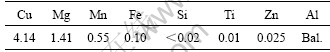
The composition of aluminum alloy used in this work is shown in Table 1. The alloy, prepared by ingot metallurgical route, was homogenized, hot-rolled, cold- rolled to 4.0 mm, then was solution heat treated at (498±2) ℃ for 1 h followed by water-quenching. Part of plate was left at room temperature for more than 96 h (condition T3). Another part was simultaneously aged at 190 ℃ for 9 h (condition T6).
Table 1 Chemical composition of 2E12 Al alloy (mass fraction, %)
Fatigue life tests were conducted on smooth specimens applying a constant maximal stress (σmax) of 185 MPa at a stress ratio (R) of 0.1 and the corresponding numbers of cycles to failure were recorded. All tests were conducted at a frequency of 140 Hz at room temperature in air. The FCGR tests were conducted on pre-cracked M (T) specimens according to GB/T 6398―2000 [10] and ASTM E 647 [11]. FCGR tests were done under a constant amplitude sinusoidal wave loading at R of 0.1 and a frequency of 10 Hz using a MTS-810 testing machine at room temperature in air.
TEM disks were electro-polished using a solution of 25% nitric acid and 75% methanol solution at -20 ℃. These disks were then examined on a JEM-2000FX electron microscope operating at 160 kV. Selected area electron diffraction (SAD) studies were performed on the same microscope operated in the diffraction mode.
The fracture analysis was carried out using a JSM-5600LV microscope. The fractured specimens after the fatigue testing were carefully cut into appropriate sizes prior to the examination.
3 Results and analysis
3.1 Microstructural results
Figs.1 and 2 represent TEM images showing the microstructures in T3 and T6 conditions, respectively. The micrographs were taken from the grains on the [001] zone axis combined with the corresponding SAD patterns. By TEM observation, it is found that neither extra diffraction in the SAD pattern nor distinct precipitates appear except iron-rich intermetallics (arrow

Fig.1 TEM image in T3 condition: (a) Bright field; (b) Corresponding SAD from [001]Al
1) and manganese-containing dispersoids (type Al20Cu2Mn3, arrow 2) [12] in T3 condition (Fig.1), which means that Cu-Mg clusters detected by APFIM and DSC [13-15] dominate in this condition.
Fig.2 shows lath-shape precipitates in T6 condition, the [001] Al SAD pattern reveals strong reflections that are consistent with S phase (arrow 3) [15-17]. This means that S phase is the main precipitate in T6 condition.
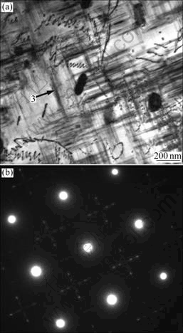
Fig.2 TEM image in T6 condition: (a) Bright field; (b) Corresponding SAD from [001]Al
3.2 Tensile properties
The results of the tensile testing are presented in Table 2. In T6 condition, the yield strength is increased by 16.3% compared with that in T3 condition. The increase in yield strength will reduce plastic deformation at the crack tip, hence resulting in the increase in FCGR (Fig.3).
Table 2 Tensile properties of alloy under various aging conditions

3.3 Fatigue life
High cycle fatigue lives are  cycles and 44 400 cycles for T3 and T6 conditions respectively at σmax=185 MPa. The value is the average value for five specimens. The fatigue life is increased by 54% in T3 condition.
3.4 Fatigue crack growth rate
The FCGR, da/dN, as a function of stress intensity factor range (ΔK) is shown in Fig.3. Paris constants C and n were evaluated from the linear region of plots of da/dN versus ΔK in Fig.3. C and n values in T3 condition are found to be 3.70×10⁻⁷ and 2.478, and in T6 condition, they are 3.74×10⁻⁷ and 2.758, respectively. The corresponding Paris equation may subsequently be written as follows:
For T3 condition:
da/dN=3.70×10-7 (?K)2.478 (1)
For T6 condition:
da/dN=3.74×10-7 (?K)2.758 (2)
The FCGR in the alloy due to two different aging conditions is compared and presented in Table 3. The da/dN values at specified ΔK levels between 10 and 20 MPa×m1/2 are determined to make the comparison. The comparison reveals that the FCGR in T3 condition is much lower than that in T6 condition. The corresponding increase in da/dN with the increase of both C and n values may be observed.
3.5 Fractography
Fig.4 represents SEM images of low speed growth area. Both fatigue fractures have transgranular character. The fatigue fracture surface of the alloy in T3 condition (Figs.4(a) and (b)) exhibits brittle fracture features, i.e., quasi-cleavage-like fracture. In contrast, the fatigue fracture surface of the alloy in T6 condition (Fig.4(c)) exhibits wave character along direction of fatigue crack propagation (FCP) due to intense plastic strain accumulation at the crack tip, and the secondary cracks and the fatigue striations are also observed (Fig.4(d)), but the striation space is very small. The difference of fracture surface supports the model of the reversed slip of dislocations discussed in detail in discussion part.
Fig.5 shows SEM images of middle speed growth area. Secondary cracks occur and striations are not clear in T3 condition. But ductile fatigue striations are the dominant features in T6 condition. It can be clearly seen, by comparison between Fig.5(a) and Fig.5(b), that T6 condition alloy has a much wider striation space due to possessing a higher FCGR.
3.6 Fatigue crack propagation path
Fig.6 shows the crack propagation paths developed in T3 and T6 conditions, respectively. Both paths are transgranular, which are in agreement with Figs.4 and 5. The crack deflects encountering grain boundary and exhibits Zigzag deflection. The crack propagation path in T3 condition exhibits larger deflection compared with that in T6 condition due to planar-reversible slip favoring the increased crack closure and tip deflection.
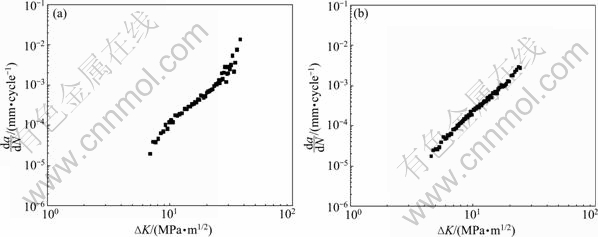
Fig.3 FCGR of 2E12 Al alloy: (a) In T3 condition; (b) In T6 condition
Table 3 da/dN values corresponding to various ΔK levels
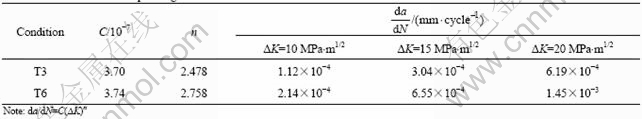
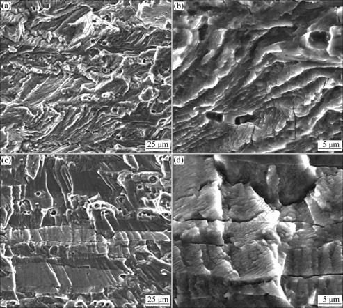
Fig.4 SEM images of 2E12 alloy showing low speed growth area: (a) In T3 condition; (b) High magnification of (a); (c) In T6 condition; (d) High magnification of (c)
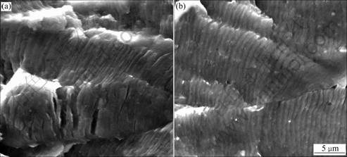
Fig.5 SEM images of 2E12 alloy showing middle speed growth area: (a) In T3 condition; (b) In T6 condition
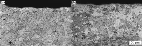
Fig.6 Typical fatigue crack propagation paths: (a) In T3 condition; (b) In T6 condition
4 Discussion
The present results demonstrate a significant difference in their FDP behaviors between T3 and T6 conditions. These can be explained on the basis of their microstructure differences.
HORNBOGEN and GAHR [18] put forward a model of reversed slip of dislocations at the crack tip during studying the influence of aging condition on the fatigue fracture behavior of Fe-Ni-Al alloy. According to Ref.[18], during cyclic loading, dislocations shear small-coherent strengthening precipitates and accumulate at the crack tip. During the unloading part of a loading, a number of dislocations will move backward on the same slip plane exactly, with minimal damage accumulation. This planar-reversible slip is considered to promote FCP resistance and reduce the FCGR in a material. On this basis, the slower FCGR in T3 condition compared to somewhat higher in T6 condition may be explained.
According to Fig.1, fine Cu-Mg clusters are the main strengthening precipitates in T3 condition. Such co-clusters are coherent and are sheared by dislocation. Under cycle loading, such co-clusters are sheared by dislocation, which promotes the movement of the reversed dislocation and reduces the number of dislocation at the crack tip, resulting in decreasing cyclic plastic deformation. It is the shearable nature of the precipitates that gives rise to the promoted FCP resistance and the reduced FCGR rate in T3 condition.
In T6 condition, the strengthening precipitates are the much coarser S phase. These precipitates are non-sheared and dislocations are likely to tangle and loop around particles. During the unloading part of a loading, the dislocations cannot move backward on the same slip plane exactly. The tip dislocations and cyclic plastic deformation are increased due to irreversible-planar slip, resulting in the decrease in FCP resistance and the increase in FCGR.
In addition, clusters that form in T3 condition can localize slip into a single-planar variant that retards cross slip. This planar slip is beneficial to the increased crack closure and tip deflection. From Fig.6, we can see that the alloy in T3 condition exhibits larger deflection compared with the alloy in T6 condition due to planar-reversible slip favoring increased crack closure and tip deflection.
The tip deflection can induce crack closure and shielding. Fig.7 represents schematic diagram of deflected crack. Based on the earlier studies [19-20], the equations for the local crack tip modeⅠand modeⅡstress intensity factors, k1 and k2, for the growth along a short kink/branch crack can be expressed as
 (3)
(3)
 (4)
(4)

Fig.7 Schematic diagram of deflected crack
where θ is the angle between the inclined main crack and the kink/branch crack (Fig.7). The effective stress intensity factor, keff, for the coplanar propagation along the deflected kink is
 (5)
(5)
If one changes k and K in Eq.(3) through Eq.(5) into the corresponding stress intensity factor ranges Δk and ΔK, Eq.(3) through Eq.(5) may be used to describe the fatigue crack growth behavior. The effective stress intensity factor range, Δ keff, can be expressed as
 (6)
(6)
When the main crack is perpendicular to the loading axis,  will be zero. Δkeff can be expressed as
 (7)
(7)
It can be concluded that Δkeff will decrease with increasing θ. Larger crack deflected angle θ is argued to promote FCR resistance by decreasing effective tip crack driving force.
It can be seen from Fig.6 that the alloy in T3 condition exhibits larger deflection compared with that in T6 condition, so it promotes FCR resistance and decreases FCRG by increasing crack closure.
5 Conclusions
(1) The alloy in T3 condition exhibits higher fatigue crack propagation resistance. The fatigue life is increased by 54% and fatigue crack growth rate is much slower than that in T6 condition.
(2) Both fatigue fractures are transgranular. But in T3 condition the secondary cracks occur and fatigue striations are not clear. In T6 condition, ductile fatigue striations are observed.
References
[1] GOLDEN P J, GRANDT A F, BRAY G H. A comparison of fatigue crack formation at holes in 2024-T3 and 2524-T3 aluminum alloy specimens [J]. International Journal of Fatigue, 1999, 21(1): S211-S219.
[2] BRAY G H, BUCCI R J, COLVIN E L, KULAK M. Effect of prior corrosion on the S/N fatigue performance of aluminum sheet alloys 2024-T3 and 2524-T3 [J]. ASTM Special Technical Publication, 1997, 1298: 89-103.
[3] WILLIAM C, JOHN L, JAMES T. Aluminum alloys for aircraft structure [J]. Advanced Materials and Processes, 2002, 160(12): 27-29.
[4] IAU J, KULAK M. A new paradigm in the design of aluminum alloys for aerospace applications [J]. Materials Science Forum, 2000, 331/337: 127-140.
[5] STARKE E A, STALEYT J T. Application of modern aluminum alloys to aircraft [J]. Progress in Aerospace Sciences, 1996, 32(2/3): 131-172.
[6] LIU Gang, ZHENG Zi-qiao, YANG Shou-jie, DAI Sheng-long, LI Shi-jie. The fatigue performance and fatigue crack propagation behavior of 2E12 Al alloy [J]. Materials for Mechanical Engineering, 2007, 31(11): 65-68. (in Chinese)
[7] LIU Gang. Study on microstructure and fatigue performance of 2E12 aluminum alloy [D]. Changsha: Central South University, 2007: 42-50. (in Chinese)
[8] DU Feng-shan, YAN Liang, DAI Sheng-long, YANG Shou-jie. Study on fatigue performance of high strength aluminum alloy [J]. Journal of Aeronautical Materials, 2009, 29(1): 96-100. (in Chinese)
[9] LI Hai, WANG Zhi-xiu, WEI Xiu-yu, ZHENG Zi-qiao. Effect of solution treatment time on microstructures and fatigue properties of aluminum alloy 2E12 [J]. Acta Aeronautica et Astronautica Sinica, 2009,30(1): 148-152. (in Chinese)
[10] GB/T 6398―2000. Standard test method for metallic materials fatigue crack growth [S].
[11] ASTM E647―93. Standard Test method for constant load amplitude fatigue crack growth rates above 10-8 m/cycle [S].
[12] WALSH J A, JATA K V, STARKE E A Jr. The influence of Mn dispersoid content and stress state on ductile fracture of 2134 type Al alloys [J]. Acta Metallurgica, 1989, 37(11): 2861-2871.
[13] STARINK M J, GAO N, YAN J L. The origins of room temperature hardening of Al-Cu-Mg alloys [J]. Materials Science and Engineering A, 2004, 387/389: 222-226.
[14] STARINK M J. The analysis of Al-based alloys by calorimetry: Quantitative analysis of reactions and reaction kinetics [J]. International Materials Review, 2004, 49(3/4): 191-226.
[15] WANG S C, STARINK M J. Precipitates and intermetallic phases in precipitation hardening Al-Cu-Mg-(Li) based alloys [J]. International Materials Review, 2005, 50(4): 193-215.
[16] WANG S C, STARINK M J. Two types of S phase precipitates in Al-Cu-Mg alloys [J]. Acta Materialia, 2007, 55(3): 933-941.
[17] KHAN I N, STARINK M J, YAN J L. A model for precipitation kinetics and strengthening in Al-Cu-Mg alloys [J]. Materials Science and Engineering A, 2008, 472(1/2): 66-74.
[18] HORNBOGEN E, GAHR K Z. Microstructure and fatigue crack growth in a γ-Fe-Ni-Al alloy [J]. Acta Metallurgica, 1976, 24(6): 581-592.
[19] COTTERELL B, RICE J R. Slightly curved or kinked cracks [J]. International Journal of Fracture, 1980, 16(2): 155-159.
[20] SURESH S, SHIH C F. Plastic near-tip fields for branched cracks [J]. International Journal of Fracture, 1986, 30(4): 237-259.
Foundation item: Project(2005CB623705) supported by the National Basic Research Program of China
Received date: 2009-10-19; Accepted date: 2010-04-19
Corresponding author: YAN Liang, Doctoral candidate; Tel: +86-13462404476; E-mail: yanliangyd2003@126.com
(Edited by YANG You-ping)

