Trans. Nonferrous Met. Soc. China 29(2019) 1689-1695
High-pressure torsion deformation process of bronze/niobium composite
S. O. ROGACHEV1, S. A. NIKULIN1, V. M. KHATKEVICH1, R. V. SUNDEEV2, D. A. KOZLOV1
1. National University of Science and Technology Ў°MISISЎұ, Leninsky pr. 4, Moscow 119049, Russia;
2. Russian Technological University Ў°MIREAЎұ, pr. Vernadskogo 78, Moscow 119454, Russia
Received 11 November 2018; accepted 19 April 2019
Abstract: The deformation process in the material volume under high-pressure torsion (HPT) was studied. As a model object for the observation of deformation process, we used a composite comprising a bronze matrix and niobium filaments. The arrangements of the niobium filaments in the bronze matrix and their size have regular geometry. This allows us to monitor and measure the displacement of the niobium filaments in the sample volume, which results from HTP. The bronze/niobium composite samples were subjected to HPT at room temperature and 6 GPa, and the number of revolutions N=1/4, 1/2, 1, 2, 3 and 5. It was shown that HPT with revolution number of 1 leads to the 360Ўг rotation of entire sample volume without sample slippage. Similar deformational behavior during HPT can be expected for high-ductility metallic materials. The increase in the number of revolutions more than 2 leads to twisting the niobium filaments in the sample volume and the formation of Ў°vortexЎұ multilayer structure. The mechanisms for the formation of such structures were discussed.
Key words: high-pressure torsion; severe plastic deformation; metal matrix composite; vortex structure
1 Introduction
At present, the high-pressure torsion (HPT) is widely used to form a nanocrystalline structure and to harden various metals and alloys [1]. The complete review of the HPT applications was made [2,3]. However, till now very little is known about the real processes occurring in the course of HPT.
The design of installations used for the realization of the HPT deformation is the development of well-known Bridgman anvil concept [4]. Initially, these installations were used to study phase transformations under very high pressures and deformations. The application of this method for the formation of nanostructures characterized by high-angle grain boundaries allowed one to consider it as a new procedure for the preparation of nanostructured materials [2].
In the course of HPT, a sample prepared in the form of a disk is placed between two anvils with flat bases and subjected to compression under a pressure of several gigapascals [3]. The bottom anvil revolves, and surface friction forces cause the shear deformation of the sample. The sample geometry allows the main volume of a material to be deformed in quasi-hydrostatic compression conditions under the action of pressure produced by outer layers of the sample. As a result, despite high degrees of strain, the sample is not broken. In some HPT installations, to decrease the outflow of a metal, the bottom base has a concave (hole).
The substantial disadvantage of HPT consists in the structural nonuniformity of prepared samples since the shear strain increases from the center of the sample to its periphery [5,6]. Some procedures used for the calculation of shear strains during HPT are available; however, the problem remains debatable [3]. The fact that, in most cases, the HPT deformation process is studied post-mortem, i.e., a deformed sample is studied, making the calculation of strains difficult. There are some studies related to in-situ investigations of the HPT deformation in literatures [7-9], i.e., in these studies, the evolution of the sample is monitored directly in the course of HPT. However, in all these studies, only changes in the physical properties or phase transformations in a sample during deformation were investigated. The monitoring of the deformation process in the course of HPT is of substantial interest. It is difficult to solve the problem since samples used for the HPT deformation are continuous and macro uniform; this fact does not allow the visual monitoring of deformation processes.
Interesting results were obtained in the course of processing of multiphase materials by the HPT method, for example, duplex steels [10-12], two-phase eutectoid Zn-22%Al alloys [13], and two-phase Cu-Ag alloys [14]. In these researches, unusual patterns of the plastic flow of the material were observed during deformation, such as double-vortex strains, shear vortices, and significant local turbulence. However, the random character of the phase distribution in the original materials made interpretation of the results difficult.
In the present study, as a model object for observation of deformation process during HPT, we used a billet of industrial low-temperature Nb3Sn-based superconductor consisting of a bronze matrix and niobium filaments, which were of the same size and formed in hexahedral clusters uniformly distributed in the matrix. The arrangements of clusters in the bronze matrix and their sizes have the regular geometry. This allows us to monitor and measure the displacement of clusters in the sample, which results from HTP.
Thus, the aim of the present work is to study the deformation process in the material under HPT by an example of a composite comprising the bronze matrix and niobium filaments.
2 Experimental
The samples cut from a cylindrical billet of industrial low-temperature Nb3Sn-based superconductor were subjected to HPT. Such a billet consists of a bronze matrix and niobium filaments, which are formed in hexahedral clusters having a regular geometry and uniformly distributed in the matrix (Fig. 1). The components of the billet (bronze matrix and niobium filaments) are characterized by adequate deformability and can be plastically deformed to high degrees of strain (typical degrees of drawing in manufacturing a superconducting wire are from 12 to 16).
The original billet was spark-cut into plates with 1 mm in thickness; disk samples with 8 mm in diameter were cut from the plates. Each of samples contains 48 clusters in average, each of which, in turn, consists of 36 niobium filaments. The length of each face of the hexahedral cluster is 560 ҰМm; the distance between centers of neighboring clusters is 1100 ҰМm.
The samples of the bronze/niobium composite were subjected to HPT at room temperature, at a pressure of 6 GPa using a hole with 0.5 mm in depth, which is located in the bottom anvil, and the number of revolutions N=1/4, 1/2, 1, 2, 3 and 5.
X-ray diffraction analysis of a longitudinal section of the samples was performed using a DRON-3M diffractometer and Co KҰБ radiation. Changes in the width of niobium and matrix reflections, which were caused by an increase in the HPT revolutions, were measured in the angular range 2ҰИ of 40Ўг-54Ўг.
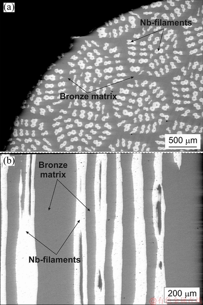
Fig. 1 Longitudinal (a) and cross-sectional (b) morphologies of bronze/niobium composite before HPT
After HPT, the bottom surface of samples was subjected to grinding and polishing; the grinding was performed using abrasive paper (P400ЁCP2500). The samples were polished using Masterprep suspension with an abrasive particle size of 0.05 ҰМm. A set of photos of the polished bottom surface (of the longitudinal section) of bronze/niobium composite samples subjected to HPT at different numbers of revolutions were taken at a magnification of 30 using a JSM-6610LV (JEOL) scanning electron microscope (SEM) and back-scattered electron mode. The photos were glued together to form a panoramic image of the whole bottom surface of the sample.
The preliminary processing of the obtained panoramic image was performed using CorelDRAW graphics software. In the course of processing, each of the hexahedral clusters consisting of niobium filaments was bounded by a polygon that was colored monochromatically. Further quantitative analysis of photos was performed using the ImageExpertPro software. In this case, the number, specific and average areas, and average perimeter of clusters were calculated.
After that, the samples subjected to HPT were spark-cut along the diameter into two fragments, which were pressed in epoxy resin, and transverse sections were prepared similarly to longitudinal sections. The panoramic image of the transverse section was taken using the scanning electron microscope and the procedure was used for the longitudinal section.
3 Results and discussion
Figure 2 shows SEM images of the surface (longitudinal section) of bronze/niobium samples subjected to HPT. Figure 3 shows schematic images of the whole surface (longitudinal section) of bronze/ niobium samples before and after HPT, which were obtained by processing the SEM images with a graphical software.
Panoramic images of the surface of bronze/niobium samples subjected to HPT show that, even after deformation with the number of revolutions N=1/4, substantial distortions of the shape of equiaxed hexahedral clusters and elongation of some niobium filaments and their displacement near the sample edges take place (Fig. 2(a)). As the number of HPT revolutions increases from 1/4 to 1, this tendency remains unchanged. At the same time, the character of the structure does not change qualitatively at HPT revolutions from 1/4 to 1 (Fig. 3).
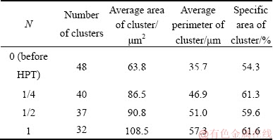
Table 1 shows quantitative characteristics of the clusters in the bronze/niobium composite samples before and after HPT. It is seen that, as the degree of deformation (i.e., the number of revolutions) increases, the number of clusters on the sample surface decreases as a result of their merging with each other near the sample edges. In this case, in turn, the average area and average perimeter of cluster increase.
After HPT with some revolutions (N=2-5), the twisting of niobium filaments is observed over the whole surface of the sample, except its center (Fig. 2(b)). In this case, the mixing of niobium and bronze areas and the formation of typical Ў°vortexЎұ structure are observed.
Vortex structures (or vortex defects) are often observed at large deformation, or dynamic deformation (for example, explosion welding) of some metallic materials [15]. Their formation occurs during the evolution of a deformed solid as a consequence of its adaptation to external mechanical loading [16]. The formation of vortex defects occurs as a result of coordinated displacement of atoms or structural elements under external load. The reason for that is the inhomogeneous stress distribution in the deformed solid [17].
It is well known that the vortices are formed during the hydrodynamic motion of a liquid, which is due to layers moving of a liquid at different speeds. The authors in Refs. [15,18,19] assume the possibility of a layered flow of a deformed metal solid when the condition of continuity between layers is satisfied, by analogy with the flow of a liquid. The turbulent plastic flow of metallic material is very characteristic when it is deformed by the HPT method, as evidenced by some researches [10,13,14,18]. However, the occurrence of turbulent plastic flow in a solid is obviously not related to the difference in the velocities of plastic flow of the layers, i.e., Kelvin-Helmholtz instability (because these velocities are small), although some similar mechanisms take place [20,21].
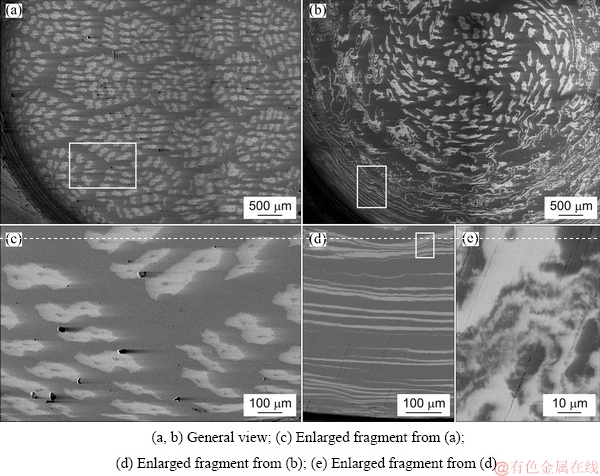
Fig. 2 SEM images of surface (longitudinal section) of bronze/niobium composite after HPT with N=1/4 (a, c) and N=5 (b, d ,e)
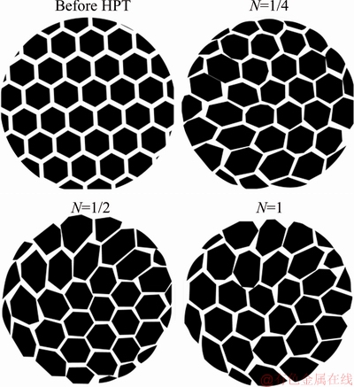
Fig. 3 Schematic images of surface (longitudinal section) of bronze/niobium composite before and after HPT
Table 1 Quantitative characteristics of clusters in bronze/ niobium composite samples before and after HPT
One of the main general reasons for the occurrence of turbulent flow during HPT is the inhomogeneous distribution of strains and the presence of strain gradients (local shear rate gradients) or local blocking of simple shear in the sample volume [17,19]. The inhomogeneous distribution of strains, for example, is confirmed by measuring the values of microhardness on the cross-section of the disk sample after HPT. Such studies have been carried out in Refs. [22-24]. The results presented indicate that the HPT deformation process is heterogeneous. The deformation is inhomogeneous in the thickness of the sample. The cross-sections with increased and decreased values of microhardness are well visible.
The most pronounced vortex structures were observed when the layered samples (sandwiches) from various metals, for example, Ў°steel/vanadium alloy/ steelЎұ [25-27], Ў°aluminum/magnesiumЎұ [28,29] and Ў°aluminium/copperЎұ [30-32] were processed by HPT. The layered sample under conditions of high pressures can be considered as a solid one, and the occurrence of a turbulent flow will occur more easily in this case.
In our case, the formation of vortex structures in bronze/niobium composite is possibly associated with the appearance of turbulent plastic flow in a bronze matrix under shear strain. The presence of niobium filaments having a deformation capacity slightly different from the bronze matrix leads to an easier occurrence of vortex strains at the interfaces between the bronze matrix and niobium filaments. This, in turn, contributes to the appearance of a developed vortex structure in the entire volume of the sample. It is important that the formation of vortex defects is possible only when the volume increases with shear strains. The increase in the volume will occur at the interfaces between the bronze matrix and niobium filaments.
To calculate the angle of displacement of niobium filament from the initial position at the distance R from the sample center, the panoramic image of the surface of the composite sample subjected to HPT was overlaid with a net with the applied image of initial (before HPT) arrangement of niobium filaments. After that, the angle of displacement of selected niobium filament from the initial position was calculated. For the number of revolutions N=1/4, the maximum angle of filament displacement was ~15Ўг; for the number of revolutions N=1, it was 30Ўг.
It should be noted that the calculation of displacements of niobium filaments using the panoramic images of the sample surface does not characterize the entire pattern of deformation, since niobium filaments during HPT can move together with the displacement of the bronze matrix, which results from the shear strain. In this case, the calculation shows the displacement of filament relatively to the adjacent filament rather than the initial position of considered filament because the initial position of the sample surface cannot be fixed. Therefore, the clearer pattern of the displacement of niobium filaments during HPT can be observed on the transverse section of the sample (Fig. 4).
SEM observation showed that the transverse section of the bronze/niobium sample subjected to HPT with the number of revolutions N=1 demonstrates twisting the niobium filaments (Fig. 4(a)). In this case, some of the filaments are observed on the longitudinal section, some are observed to be angularly cut, and some are observed to be transversely cut. This fact indicates (regarding geometrical considerations) the rotation of filaments by a revolution in the bronze matrix, confirming that HPT with N=1 leads to 360Ўг Ў°revolutionЎұ of sample volume without sample slippage.
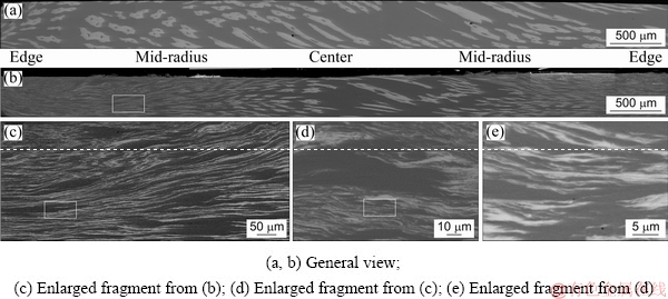
Fig. 4 SEM images showing cross-section of bronze/niobium composite after HPT with N=1 (a) and N=5 (b-e)
The increase in the number of revolutions from 2 to 5 leads to twisting the niobium filaments along the whole transverse section of the sample except its center; this pattern is similar to that observed for the longitudinal section (Fig. 4(b)). Expanded fragments of the sample structure show that the thickness of individually elongated filaments does not exceed several hundred nanometers. In this case, the mixing of niobium filaments and bronze matrix and the formation of typical Ў°vortexЎұ structure are also observed.
X-ray diffraction analysis shows that as the number of revolutions during HPT increases, the broadening of X-ray diffraction reflections of both niobium and matrix takes place (Fig. 5). In this case, the broadening of niobium reflection is less intense as compared with that of the matrix. In particular, the width of the niobium reflection before HPT is 0.404Ўг; as the number of revolutions increases from 1/4 to 5, the width of the niobium reflection increases slightly to 0.544Ўг. The most marked broadening of reflections is observed for the number of revolutions from 1 to 2 (from 0.434Ўг to 0.524Ўг). At the same time, the width of the matrix reflection even after HPT with N=1/4 increases from 0.392Ўг to 0.676Ўг; further increase in the number of revolutions leads to a monotonic increase in the width of the niobium reflection from 0.993Ўг to 1.009Ўг.
Such a behavior of the components of the composite billet (bronze matrix and niobium filaments) can be related to their different deformation mechanisms with increasing number of revolutions during HPT and different deformation ability of bronze and niobium (as compared to bronze matrix, the niobium filaments are more plastic and have lower ability to cold-work hardening). As a result of HPT, first the bronze matrix undergoes the shear deformation; this fact explains the substantial broadening of X-ray diffraction reflections of bronze even at low strain (at a low number of revolutions). As the number of revolutions increases, the deformation of the bronze matrix increases. This is accompanied by a monotonic increase in the width of diffraction reflections.
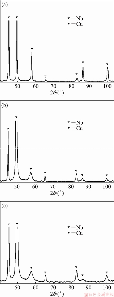
Fig. 5 Fragments of XRD patterns of bronze/niobium composite before (a) and after HPT with N=1 (b) and N=5 (c)
On the contrary, the niobium filaments at low strain (the number of revolutions from 1/4 to 1) mainly undergo the linear deformation, i.e. the elongation and twisting of them in the bronze matrix are observed. Taking into account the high deformation ability of niobium filaments, such deformation likely does not lead to the substantial increase in the density of dislocations and, therefore, is accompanied by a slight broadening of diffraction reflections. As the number of revolutions increases to 2, the mixing of niobium filaments and the bronze matrix is observed; more substantial shear deformation of niobium filaments occurs, which is accompanied by broadening the diffraction reflections.
It should be noted that the obtained results are obviously not universal. Similar deformation behavior during HPT can be expected for high-ductility metallic materials. In the case of HPT-deformation of high- strength metallic materials, for example, medium- and high-carbon steels, tungsten alloys, the slipping of the samples between the anvils of HPT-device was often observed; and the slipping often overlooked by the researchers [33,34]. As a result, HPT with N=1 will lead to a rotation of the entire sample volume by an angle of less than 360Ўг. Therefore, new research is needed to analyze the deformation behavior of such materials during HPT.
4 Conclusions
(1) The observation of the HPT deformation process was performed by an example of a composite comprising bronze matrix and niobium filaments which are formed in hexahedral clusters. The arrangements of clusters in the bronze matrix and their size have regular geometry; this allows to monitor the displacement of clusters in the sample volume, which results from HTP.
(2) HPT with revolution number of 1 (N=1) leads to the 360Ўг rotation of entire sample volume. Similar deformation behavior during HPT can be expected for high-ductility metallic materials.
(3) The increase in the number of revolutions from 2 to 5 leads to twisting the niobium filaments in the sample volume and formation of Ў°vortexЎұ structure.
Acknowledgments
The work was carried out with financial support from the Ministry of Science and Higher Education of the Russian Federation in the framework of Increase Competitiveness Program of NUST Ў°MISiSЎұ (No. K2-2019-008), implemented by a governmental decree dated 16th of March 2013, N211. The SEM analysis was carried out using the equipment of the Central Research Center Ў°Material Science and MetallurgyЎұ of the National University of Science and Technology Ў°MISISЎұ.
References
[1] VALIEV R Z, ZHILYAEV A P, LANGDON T G. Bulk nanostructured materials: Fundamentals and applications [M]. New Jersey: John Wiley & Sons, Inc., 2014.
[2] ZHILYAEV A P, LANGDON T G. Using high-pressure torsion for metal processing: Fundamentals and applications [J]. Progress in Materials Science, 2008, 53: 893-979.
[3] EDALATIA K, HORITA Z. A review on high-pressure torsion (HPT) from 1935 to 1988 [J]. Materials Science and Engineering A, 2016, 652: 325-352.
[4] BRIDGMAN P W. Effects of high shearing stress combined with high hydrostatic pressure [J]. Physical Review, 1935, 48: 825-847.
[5] KAWASAKI M, FIGUEIREDO R B, HUANG Y, LANGDON T G. Interpretation of hardness evolution in metals processed by high-pressure torsion [J]. Journal of Materials Science, 2014, 49: 6586-6596.
[6] VORHAUER A, PIPPAN R. On the homogeneity of deformation by high pressure torsion [J]. Scripta Materialia, 2004, 51: 921-925.
[7] LEVITAS V I, MA Y Z, SELVI E, WU J Z, PATTEN J A. High- density amorphous phase of silicon carbide obtained under large plastic shear and high pressure [J]. Physical Review B, 2012, 85: 054114.
[8] SUNDEEV R V, SHALIMOVA A V, GLEZER A M, PECHINA E A, NOSOVA G I. In situ observation of the Ў°crystalline-amorphous stateЎұ phase transformation in Ti2NiCu upon high-pressure torsion [J]. Materials Science and Engineering A, 2017, 679: 1-6.
[9] ALEXANDROVA M M, BLANK V D, BUGA S G. Phase transitions in Ge and Si subjected to shear under pressures up to 12 GPa and the P-T-ҰГ diagrams of these elements [J]. Physics of the Solid State, 1993, 35: 663-667.
[10] HUANG Y, KAWASAKI M, LANGDON T G. An investigation of flow patterns and hardness distributions using different anvil alignments in high-pressure torsion [J]. Journal of Materials Science, 2013, 48: 4533-4542.
[11] CAO Y, WANG Y B, ALHAJERI S N, LIAO X Z, ZHENG W L, RINGER S P, LANGDON T G, ZHU Y T. A visualization of shear strain in processing by high-pressure torsion [J]. Journal of Materials Science, 2010, 45: 765-770.
[12] HUANG Y, KAWASAKI M, LANGDON T G. Influence of anvil alignment on shearing patterns in high-pressure torsion [J]. Advanced Engineering Materials, 2013, 15: 747-755.
[13] CAO Y, KAWASAKI M, WANG Y B, ALHAJERI S N, LIAO X Z, ZHENG W L, RINGER S P, ZHU Y T, LANGDON T G. Unusual macroscopic shearing patterns observed in metals processed by high-pressure torsion [J]. Journal of Materials Science, 2010, 45: 4545-4553.
[14] TIAN Y Z, AN X H, WU S D, ZHANG Z F, FIGUEIREDO R B, GAO N, LANGDON T G. Direct observations of microstructural evolution in a two-phase Cu-Ag alloy processed by high-pressure torsion [J]. Scripta Materialia, 2010, 63: 65-68.
[15] KONSTANTINOVA T E. Evolution of the dislocation structure of metallic systems under high pressure [J]. Physics and High Pressure Technology, 2009, 19: 7-29. (in Russian)
[16] POPOV V L, PSAKHIE S G, DMITRIEV A, SHILKO E. Quasi-fluid nano-layers at the interface between rubbing bodies: Simulations by movable cellular automata [J]. Wear, 2003, 254: 901-906.
[17] PSAKHIE S G, SMOLIN A Y, SHILKO E V, KOROSTELEV S Y, DMITRIEV A I, ALEKSEEV S V. About the features of transient to steady state deformation of solids [J]. Journal of Materials Science and Technology, 1997, 13: 69-72.
[18] KULAGIN R, BEYGELZIMER Y, IVANISENKO Y, MAZILKIN A, HAHN H. High pressure torsion: From laminar flow to turbulence [J]. IOP Conference Series: Materials Science and Engineering, 2017, 194: 012045.
[19] KULAGIN R, BEYGELZIMER Y, IVANISENKO Y, MAZILKIN A, HAHN H. Modelling of high pressure torsion using FEM [J]. Procedia Engineering, 2017, 207: 1445-1450.
[20] POURYAZDAN M, KAUS B J P, RACK A, ERSHOV A, HAHN H. Mixing instabilities during shearing of metals [J]. Nature Communications, 2017, 8: 1611.
[21] QIA Y S, KOSINOVA A, KILMAMETOV A R, STRAUMAL B B, RABKIN E. Plastic flow and microstructural instabilities during high-pressure torsion of Cu/ZnO composites [J]. Materials Characterization, 2018, 145: 389-401.
[22] KAWASAKI M, FIGUEIREDO R B, LANGDON T G. Twenty-five years of severe plastic deformation: Recent developments in evaluating the degree of homogeneity through the thickness of disks processed by high-pressure torsion [J]. Journal of Materials Science, 2012, 47: 7719-7725.
[23] FIGUEIREDO R B, AGUILAR M T P, CETLIN P R, LANGDON T G. Deformation heterogeneity on the cross-sectional planes of a magnesium alloy processed by high-pressure torsion [J]. Metallurgical and Materials Transactions A, 2011, 42: 3013-3021.
[24] FIGUEIREDO R B, LANGDON T G. Development of structural heterogeneities in a magnesium alloy processed by high-pressure torsion [J]. Materials Science and Engineering A, 2011, 528: 4500-4506.
[25] ROGACHEV S O, NIKULIN S A, ROZHNOV A B, KHATKEVICH V M, NECHAYKINA T A, GORSHENKOV M V, SUNDEEV R V. Multilayer Ў°steel/vanadium alloy/steelЎұ hybrid material obtained by high-pressure torsion at different temperatures [J]. Metallurgical and Materials Transactions A, 2017, 48: 6091-6101.
[26] ROGACHEV S O, SUNDEEV R V, KHATKEVICH V M. Evolution of the structure and strength of steel/vanadium alloys/steel hybrid material during severe plastic deformation [J]. Materials Letters, 2016, 173: 123-126.
[27] NIKULIN S A, ROGACHEV S O, ROZHNOV A B, KHATKEVICH V M, NECHAIKINA T A, MOROZOV M V. Structure and properties of a layered steel/vanadium alloy/steel composite prepared by high-pressure torsion [J]. Russian Metallurgy (Metally), 2016, 2016: 375-379.
[28] QIAO X G, LI X, ZHANG X Y, CHEN Y, ZHENG M Y, GOLOVIN I S, GAO N, STARINK M J. Intermetallics formed at interface of ultrafine grained Al/Mg bi-layered disks processed by high pressure torsion at room temperature [J]. Materials Letters, 2016, 181: 187-190.
[29] AHN B, ZHILYAEV A P, LEE H J, KAWASAKI M, LANGDON T G. Rapid synthesis of an extra hard metal matrix nanocomposite at ambient temperature [J]. Materials Science and Engineering A, 2015, 635: 109-117.
[30] BOUAZIZ O, KIM H S, ESTRIN Y. Architecturing of metal-based composites with concurrent nanostructuring: A new paradigm of materials design [J]. Advanced Engineering Materials, 2013, 15: 336-340.
[31] OH-ISHI K, EDALATI K, KIM H S, HONO K, HORITA Z. High-pressure torsion for enhanced atomic diffusion and promoting solid-state reactions in the aluminumЁCcopper system [J]. Acta Materialia, 2013, 61: 3482-3489.
[32] KULAGIN R, BEYGELZIMER Y, IVANISENKO Y, MAZILKIN A, STRAUMAL B, HAHN H. Instabilities of interfaces between dissimilar metals induced by high pressure torsion [J]. Materials Letters, 2018, 222: 172-175.
[33] QIAN Chen-hao, HE Zi-yang, LIANG Cheng, JI Wei-xi. Microstructure and hardness of W-25Re alloy processed by high-pressure torsion [J]. Transactions of Nonferrous Metals Society of China, 2017, 27: 2622-2629.
[34] LI Ping, WANG Xue, XUE Ke-min, TIAN Ye, WU Yu-cheng. Microstructure and recrystallization behavior of pure W powder processed by high-pressure torsion [J]. International Journal of Refractory Metals and Hard Materials, 2016, 54: 439-444.
ЗаНӯ/окёҙәПІДБПөДёЯС№ЕӨЧӘұдРО№эіМ
S. O. ROGACHEV1, S. A. NIKULIN1, V. M. KHATKEVICH1, R. V. SUNDEEV2, D. A. KOZLOV1
1. National University of Science and Technology Ў°MISISЎұ, Leninsky pr. 4, Moscow 119049, Russia;
2. Russian Technological University Ў°MIREAЎұ, pr. Vernadskogo 78, Moscow 119454, Russia
ХӘ ТӘЈәК№УГУЙЗаНӯ»щМеәНокЛҝЧйіЙөДёҙәПІДБПОӘДЈРН¶ФПуЈ¬СРҫҝёЯС№ЕӨЧӘ(HPT)ПВІДБПМеДЪөДКөјКұдРО№эіМЎЈокЛҝөДіЯҙзәНЖдФЪЗаНӯ»щМеЦРөДЕЕБРҫщҫЯУР№жФтөДјёәОРОЧҙЈ¬ХвК№ОТГЗДЬ№»јаІвәНІвБҝСщЖ·ЦРокЛҝУЙУЪёЯС№ЕӨЧӘ¶шөјЦВөДО»ТЖЎЈҪ«ЗаНӯ/окёҙәПІДБПФЪКТОВЎў6 GPa С№БҰПВҪшРРёЯС№ЕӨЧӘЈ¬ЧӘКэN=1/4Ўў1/2Ўў1Ўў2Ўў3 әН5ЎЈҪб№ыұнГчЈ¬өұЧӘКэОӘ1КұЈ¬ХыёцСщЖ··ўЙъ360ЎгРэЧӘЈ¬Г»УРСщЖ··ўЙъ»¬ТЖЎЈёЯЛЬРФҪрКфІДБПФЪHPT№эіМЦРТІ»б·ўЙъАаЛЖөДұдРОРРОӘЎЈөұЧӘКэФцјУі¬№э2КұЈ¬КФСщМеДЪөДокЛҝ·ўЙъЕӨЗъЈ¬РОіЙЎ°РэОРЎұЧҙ¶аІгҪб№№ЎЈОДЦРМЦВЫҙЛҪб№№өДРОіЙ»ъАнЎЈ
№ШјьҙКЈәёЯС№ЕӨЧӘЈ»ҙуЛЬРФұдРОЈ»ҪрКф»щёҙәПІДБПЈ»РэОРҪб№№
(Edited by Wei-ping CHEN)
Corresponding author: S. O. ROGACHEV; E-mail: csaap@mail.ru
DOI: 10.1016/S1003-6326(19)65075-2

