


Trans. Nonferrous Met. Soc. China 22(2012) 1981-1988
Microstructure and depositional mechanism of Ni-P coatings with nano-ceria particles by pulse electrodeposition
ZHOU Xiao-wei1, SHEN Yi-fu1, JIN Hui-ming2, ZHENG Ying-ying1
1. College of Materials Science and Technology, Nanjing University of Aeronautics and Astronautics,Nanjing 210016, China;
2. College of Mechanical Engineering, Yangzhou University, Yangzhou 225127, China
Received 10 August 2011; accepted 28 October 2011
Abstract: Nano-CeO2 (RE) particles were co-deposited into Ni-P binary composite coatings by applying pulse current (PC) under ultrasonic (U) field. Morphology, chemical content and crystal microstructure were characterized by environmental scanning electron microscopy (E-SEM) with energy dispersive X-ray analysis (EDXA), XRD diffractometry and transmission electron microscopy (TEM). Experimental results show that Ni-P coating reinforced with 15g/L nano-CeO2, in amorphous state and with compact structure, can be improved in the microhardness from HV0.2580 to HV0.2780 by annealing at 600 ℃ for 2 h. The highest content of codeposited Ce and deposition rate can reach 2.3% and 68 μm/h, respectively. Furthermore, the effect of RE adsorption and pulse overpotential on depositional mechanism was investigated. n-CeO2 particles or Ce4+ ions with strong adsorption capacity acted as the catalytic nucleus to improve densification effectively. During annealing at 600 ℃ for 2 h, n-CeO2 particles will uniformly adsorb on crystal grain to preferentially pad and heal up gaps of cracking Ni boundaries, promoting dispersion strengthening with refiner-grained structure.
Key words: Ni-P coating; pulse electrodeposition; overpotential; depositional mechanism; CeO2
1 Introduction
Cerium oxide (CeO2), as one of the most powerful and fascinating rare earth oxides, has been widely applied to catalyst systems, solid state electrolytes, and high temperature ceramics, due to its good anti-corrosion property, wear resistance and excellent oxidation performance [1-3]. Compared with the conventional pure nickel coatings, several coatings (such as Ni-P [4], Ni-W [5], Ni-based [6]) reinforced with nano-CeO2 (RE) particles exhibit more crystal refinement, denser structure and better mechanical properties.
Pulse current (PC) power, bidirectional voltage with pulse current and fast duty cycle, is expected to be of great overpotential to electrodeposit nanocomposite coatings. PC has a more significant effect on depositional mechanism, metal recrystallization and concentration polarization in several more ways than direct current (DC) deposition, as reported by XUE et al [7].
Previous study on Ni-P coatings only focused on the experimental procedure, chemical content, morphology analysis, or microstructural characterization. SEO et al [8] indicated that a significant improvement on microstructural evolution and mechanical properties of Ni-P coatings are associated with precipitated Ni3P phase and recrystallization. JIN et al [9] illustrated that Ni-P/CeO2 coatings prepared by pulse electrodeposition have compact microstructure and good corrosion resistance. SONG et al [10] evaluated the corrosion resistance and wear property of Ni-W coatings with CeO2 incorporation. Recently, C?R?C et al [11] discussed the correlation between crystal microstructure and corrosion resistance of Ni-Co coatings incorporated with both CeO2 and La2O3 nanoparticles. However, little work has been done on the diffusion model of Ni-P/n-CeO2 composite coatings by pulse current (PC)+ultrasonic (U) and structural revolution during high annealing treatment. In this work, we attach importance to the codepositional mechanism based upon RE adsorption and dispersed strengthening, especially with respect to the role of pulse overpotential.
2 Experimental
2.1 Materials
Iron plate with dimensions of 20 mm×10 mm×0.5 mm and nickel plate (purity≥ 99.5%) with dimensions of 30 mm×20 mm×2 mm were employed as the cathode and anode, respectively. It was mechanically polished, immersed in a acetone solution, activated in a 5% HCl solution, and then rinsed with distilled water. All the chemical reagents used in this experiment were in analytical grade (AR). Electrolyte was composed of nickel sulphate (NiSO4・6H2O) 280 g/L, nickel chloride (NiCl2・6H2O) 40 g/L, phosphite nickel (NaH2PO3・7H2O) 20 g/L, surface active agent 0.8-1.5 g/L. In addition, pH value was measured by an HM-20E pH meter and adjusted with 15% NH3・H2O or 25% H2SO4 solution to hold an appropriate value of 2.8-3.2. Bath temperature was held at 55-65 ℃ by thermostatic water bath to increase the solubility limit of n-CeO2 particles. After finishing deposition, all the samples were cleaned in deionized water for 5 min to remove loose nanoparticles adsorbed onto coatings. The average thickness of coatings was 50 μm.
2.2 Dispersion of RE nanoparticles
An average size of CeO2 particles (purity≥99.95 %) was estimated to be 20-50 nm supplied by AR supplier. To work out the agglomerate problem caused by n-CeO2 solid particles, oscillating field simulated from ultrasonic generator (45 kHz /50 W) was used to make 15 g/L RE particles pretreat into nanosuspension. In addition, RE particles were put into the electrolyte after being hold statically for 15-25 min. Prior to electrodeposition, mechanically stirring of 80-100 r/min was employed to promote surface active agent mixed with CeO2 particles and the electrolyte for 2 h. Afterwards, mechanically stirring and ultrasonic field will uninterruptedly provide great impetus for nanoparticles to be transported from the double electrode layer to the diffuse interface [2]. Morphology characterized by E-SEM in Fig. 1(a), reveals good homodisperse of n-CeO2 particles. Uniform distribution of nanoparticles with an oval-shaped feature in composite coatings was also characterized by TEM (Fig. 1(b)).
2.3 Characterization
Morphology and chemical content were characterized by an environmental scanning electron microscope (Hitachi S-4800) operated at 10 kV (E-SEM, Hitachi/XL-30) and energy dispersive X-ray analysis (EDXA). XRD patterns were examined by X-ray diffractionometer (XRD/max-2500) with monochromatic radiation Cu Kα (λ=1.5406 ?). Microstructure and selected area electron diffraction patterns (SAED) were viewed with transmission electron microscope (TEM, Hitachi/JEOL-2000FX). An electro double tray analyzing balance (TG328) was used to calculate deposition rate by weighing method. A double pulse power supply (SMD-30S) was carried out to electroplate the coatings. Ultrasonic generator (KQ-100VDB) was applied to simulating the oscillating field. Muffle furnace (DC-B) was employed to make annealing treatment. Micro-hardness was tested by a Vickers (Leica VMHT), using a loading force of 1.96 kN and holding for 15 s, and each microhardness was an average value of three points of test results.
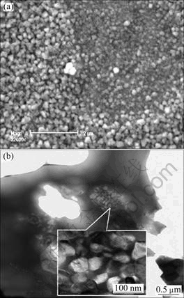
Fig. 1 Images of nano-sized CeO2 particles: (a) Uniform distribution after being pretreated by E-SEM; (b) Oval-shaped feature in composite coatings by TEM
3 Results and discussion
3.1 Surface morphology by E-SEM
Pure Ni-P and Ni-P/n-CeO2 coatings were synthesized at an average current density of 2.0 A/dm2 in the same electrolyte, and the processing parameters of electrodeposition were as follows: PC frequency of 1500 Hz, duty cycle of 25%, ultrasonic frequency and power of 45 kHz and 50 W, without and with 15 g/L RE addition. Surface morphology characterized by E-SEM, as shown in Fig. 2(a), indicates that Ni-P coating prepared by DC exhibits coarse Ni-P grains. While composite coating synthesized by PC with 15 g/L RE addition shows finer-grained state, as illustrated in Fig. 2(b), which is in good agreement with result of LI et al [12]. It can be anticipated that original RE particles (CeO2 or Ce4+) adsorbed on the catalytic sites and acted as the direction are favorable to obtain more nucleus for crystal growth, which will be helpful to codeposit with Ni grains to from nanocrystalline Ni-P/n-CeO2 coatings. Once cavitation bubble produced by ultrasonic power is shattered, alloying ions (such as Ni2+ and Ce4+) will get great impetus to be transported into the active interface, and then the coarse grains can be destroyed by the great impetus and divided into more crystal nucleus to make grain refine, promoting the plastic deformation and the dislocation density, as reported by QU et al [2]. Meanwhile, pulse power can also provide a great pulse impetus and transient high temperature to make the matrix grain disperse into the dislocation layer. Alloying ions (such as Ce4+, Ni2+, ) will be uninterruptedly supplied by the pulse impetus to reduce concentration polarization at the diffuse interface of double barrier layer [13]. Ni-P coatings incorporated with CeO2 particles are supposed to have compact structure, also holding the typical Ni-P cellular state of steamed bread pattern which has been confirmed by E-SEM observation shown in Fig. 2(c).
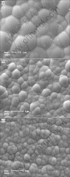
Fig. 2 E-SEM images of Ni-P coatings synthesized by DC (a), and PC with 15 g/L RE addition without (b) and with ultrasonic field (45 kHz, 50 W) (c)
3.2 Deposition mechanism
3.2.1 RE adsorption
The standard potential of Ce element transformed from Ce4+ is more negative, generally close to -2.5 V, while the cathode potential of Ni2+ is more positive (such as Ni2+→Ni, φ0=-0.25 V; Ce4+→Ce, φ0=-2.5 V). It was reported that Ce4+ ions will be very difficult to be reduced directly from the aqueous solution to codeposit with Ni matrix grain. However, with the aid of ultrasonic condition and magnetic stirring, n-CeO2 particles or Ce4+ ions (CeO2→Ce4+, pH=2.8-3.2) will be transported to the diffuse interface between the double barrier layers by the great pulsed impetus, reducing concentration polarization. Schematic illustration of Ni-RE coelectro- deposition may be supposed as Fig. 3(a). The codepositional mechanism suggests that the phosphorous oxyacid reduction is mainly depended on H+ reduction with the formation of a gaseous intermediate phosphine (PH3). Ni2+ reduction and PH3 oxidation would then occur simultaneously, which is due to the protons deficit at the interface layer of high polarization. Possible mechanism for Ni-P coatings by electrodeposition, referring to ORDINE et al [14], is listed as follows:


 (1)
(1)
 (2)
(2)
 (3)
(3)
 (4)
(4)
Evolution of OH- caused by hydrogen evolution will increase the pH value, close to the cathode. Ce4+ ions, which adsorbed on the surface of cathode near double electrode layer, will transform into Ce(OH)4 film so as to modify the depositional characteristic near he diffusion interface and prevent the ions from being exchanged, resulting in the lower current efficiency. The main cathodic process is possibly given by:
 (5)
(5)
 (6)
(6)
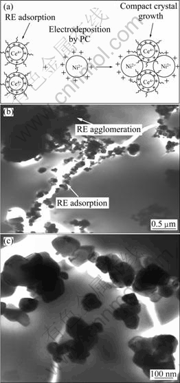
Fig. 3 Schematic illustration of RE-Ni coelectrodeposition (a), RE particles uniformly adsorbed along cracking gaps (b), and magnification (c) showing morphology in (b)
With increasing the RE concentration in the electrolyte, excess Ce4+ ions adsorbed on the surface of cathode will be in saturation, producing a continuous Ce(OH)4 film to bring about poor stability without available catalytic-activity, as illustrated in Fig. 3(b). Once abundant Ce(OH)4 film is cumulated, the active surface will be covered by this film to prevent Ni2+ or Ce4+ ions from being exchanged. Meanwhile, the electric discharging of metal ions will be seriously hindered to reduce the current efficiency, so it will be more difficult for Ce4+ ions to produce more nucleation. Interestingly, Ce4+ ion, as one of a few cations that can produce specific adsorption on the electrode surface, has a large number of extranuclear electrons with strong adsorption capacity. Ce4+ ions serving as catalytic sites will make Ni2+ discharge more electrons with positive potential (Zeta) to enhance nucleation, as indicated by FU and LIN [15]. Namely, it will be favourable to increase the adsorbability of Ni2+ and Ce4+ ions to promote them co-deposit effectively. Meanwhile, n-CeO2 particles will adsorb Ni2+ or Ni[P(OH)4]2+ and then attract as the growing center to shield the growing space or directions from coarsening growth of Ni grains. YANG et al [13] reported that Ce4+ or n-CeO2 would be co-deposited on Ni grain by its adsorption capacity rather than reduction reaction. CeO2 particles, dispersed by ultrasonic (U) field are, in general, uniformly distributed and co-deposited with Ni grain along cracking gaps, which is very useful to form alloying coatings and improve crack propagation resistance, as seen in Fig. 3(c).
3.2.2 Pulse overpotential
It is well known that nano-crystal growth mainly depends upon the number of original nuclei. Whereas, it will be prone to produce coarse grains during the rapid grain growth. Therefore, it is need to cope with the challenge between more nucleation and rapid crystal growth. Interestingly, it will achieve a higher polarization overpotential (ηc) with increasing nucleation rate (Pw), as illustrated by Eq. (7). The mechanism of crystallization overpotential by CHANG et al [16] described that more nucleation is mainly associated with the pulsed characteristic resulted from ultrasonic field and pulse power. Overpotential (ηc), defined in Eq. (8), mainly depends upon the electron discharge of metal ions during the course of electrochemical reaction.
 (7)
(7)
 (8)
(8)
where Pw is the nucleation rate; a and b represent the proportionality constants (a, b>0); ηc is the polarization overpotential; J0 and J are the current densities of exchange and cathode, respectively; T is thermodynamic temperature; R is the gas constant; F is the Faraday constant; n is the electronic number; α is the coefficient of diffusion in electrolyte.
Accordingly, as for DC deposition, those alloying ions (such as Ce4+, Ni2+ ) cannot be exchanged and reduced sufficiently because of the asymmetrical electric field and concentration polarization causing the electrode potential far from equilibrium value. Based on RE adsorption and overpotential from pulse current, the depositional mechanism near the double barrier layer has been managed (see Fig. 4). Overpotential of pulse current (ηcp) and direct current (ηcd) can be presented as:
 (9)
(9)
 (10)
(10)
where Jp and Jd are the pulse and direct current densities, respectively.
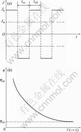
Fig. 4 Characteristic of double-pulsed current (a) and relationship between duty cycle of pulse current and polarization overpotential (b)
To fairly compare ηcp and ηcd, an average value of current density about pulse and direct is supposed to the same. Fast duty cycle and pulse current will enhance the polarization overpotential, as indicated by Eq. (11). Pulse current can provide a great pulsed impetus for alloying ions, making the internal electrons exchange rapidly at the solution/metal interface. Meanwhile, it will also improve current efficiency and reduce concentration polarization so as to ensure these ions could be supplied uninterruptedly.
When
 ,
,
 ;
;
then

 (11)
(11)
where Jm is an average current density; γ is the duty cycle (1>γ>0, lgγ<0 ); ton and toff refer to the positive- and negative-time of double pulse power, respectively.
3.3 Effect of RE addition on deposition rate
EDXA analyses of ceria and nickel, as shown in Fig. 5, indicate that content of Ce alloying element in coatings will increase with increasing CeO2 content. The highest contents of codeposited Ce and P can reach 2.3% and 8.6% in coatings with 15 g/L RE addition. In addition, with RE concentration ranging from 0 to 20 g/L, the deposition rate can achieve 68 μm/h, as shown in Fig. 6, which is mainly related to original RE particles (CeO2 or Ce4+) serving as the catalytic sites to capture more nuclei for crystal growth. In addition, pulse wave and mechanically rabbling can ensure alloying ions to be uninterruptedly supplied to decrease concentration polarization. So coarse grain will be destroyed into more crystal nucleus to improve the number of nuclei. However, deposition rate will decrease with increasing RE addition more than 20 g/L, due to the congregation of solid nanoparticle and poor stability in electrolyte.
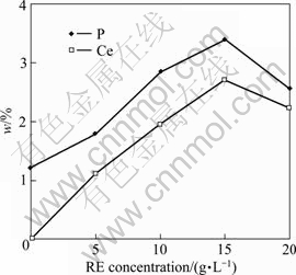
Fig. 5 Effect of RE concentration on codeposited content of (P, Ce) by EDXA analysis
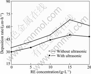
Fig. 6 Effect of RE concentration and ultrasonic field on deposition rate
In the experiment, electro double tray analyzing balance (TG328) was used to measure deposition rate by weighing method, using the following Eq.(12) as:
 (12)
(12)
where ν is deposition rate; ?m is the mass gain of specimens before or after deposition, ?m=mas-plated- msubstract; ρ is the average density of composite coatings, calculated by weighing and cubing method; t is the time duration of electroplating; As is the surface area of cathode.
3.4 Microstructure and phase analysis
XRD analysis has been applied to investigating the phase composition. According to Fig. 7, it is found that CeO2 addition does not have enough power to take a great effect on crystal growth for every grain. Obviously, crystal growth of Ni (111) plane is predominant while the intensity of both Ni(200) and (311) are significantly stronger with 15 g/L RE addition. During annealing at 600 ℃ for 2 h, recrystallized nucleation will reoccur at the preferential location on Ni (111) and NiO (101) faces to promote them stronger than (200) and (311) in Ni-P coatings. To review the co-depositional mechanism (as mentioned above), it is anticipated that the reduction of P would be inhibited and cannot be deposited alone by codeposition with iron-group metals, which is due to its non-electric characteristics at higher polarizations. Therefore, the intensity of P peak is not clear in the XRD patterns. Furthermore, the peak pattern corresponding to CeO2 (400) is observed from the patterns of coatings incorporated with 15 g/L RE. Faces of Ni3P (330) and NiO (101), (222) are also found and intensities increase with increasing annealing temperature ranging from 400 to 600 ℃. To survey each XRD pattern, the dominated orientation of Ni (111) has been distributed to different faces, including Ni(200) and (311), NiO (101) and (222), Ni3P (330), etc. It can be strongly suggested that ultrasonic field can restrain Ni and NiO crystal growth to obtain refiner-grained structure.

Fig. 7 XRD patterns of coatings incorporated with and without RE addition when annealed at different temperatures
Ni-P coatings without and with RE incorporation were annealed at 400 ℃ or 600 ℃, holding for 2 h in the muffle furnace without any protective atmosphere. As-plated Ni-P coatings show coarse Ni grain and large boundary, as seen in Fig. 8(a). Ni grain does grow up quickly during annealing at 400 ℃ for 2 h, even more than 300 nm, giving rise to cracking boundary and hot micro-cracks occur, as shown in Fig. 8(b). Cracking gaps and high tensile stress caused by crystal defect without being reasonably managed will be prone to obtain coarse structure with poor microhardness. However, with 15 g/L RE addition, nano-sized RE preferentially pads and occupies the cracking gaps to limit growing spaces for Ni grain at 400 ℃, as observed in Fig. 8(c). While annealing at 600 ℃, the precipitated phases (such as Ni3P, CeO2 or NiCe2O4) will diffuse to make dispersed- strengthening along the edge of cracks propagation, promoting large crystal boundary to obtain compact structure. Furthermore, Ni grain does not grow up into coarse ones quickly with increasing temperature, less than 150 nm, as shown in Fig. 8(d), which has been proved by the previous study [17].
To further study the structural revolution, SAED patterns obtained from TEM indicate that Ni-P coatings have been transformed from as-plated microlites into typical as-annealed crystalline structure at 400 or 600 ℃ in Figs. 8(a) and (b). Crystal texture with unstable amorphous or microlite as-plated state will change from preferent growth with irregular state into typical crystalline structure spontaneously, especially for matrix Ni crystal growth annealed above 600 ℃, as illustrated by ZHOU et al [18]. Nevertheless, with 15 g/L RE addition, it will hold amorphous or microlite state when annealed at 400 ℃ or 600 ℃, as seen in Figs. 8(c) and (d). Amorphous or microlite state can own compact microstructure without lots of boundaries, which is favourable to hinder grain boundary sliding.
3.5 Microhardness
Adding some active RE elements (such as Ce, La and Y) into coating could acquire good structure through uniform distribution along crystal defects by catalytic adsorption, producing dispersion strengthening at large gaps of boundaries or cracking micro-cracks by solution- hardening treatment during annealing treatment [19,20]. Microhardness (HV0.2) determined by Vicker’s tester under a loading force of 1.96 N and holding for 15 s was calculated by the following expression:
 (13)
(13)
where P is the loading force (N), d is the diagonal line length of importation press (μm).

Fig. 8 TEM bright field images of Ni-P coatings by DC and annealing at 400 ℃ (a) and 600 ℃ (b), with 15 g/L RE addition by PC+U when annealed at 400 ℃ (c) and 600 ℃ (d)
Microhardness value calculated from Eq. (13) displays that it has a range from HV425 in as-plated state to HV455 and HV520, corresponding to Ni-P coatings in as-annealed state at 400 ℃ and 600 ℃, as shown in Fig. 9. Moreover, with 10 g/L or 15 g/L RE addition, it is significantly improved, varying from HV515 to HV620 and HV680, and from HV575 to HV650 and HV780, respectively. Nevertheless, with more than 20 g/L RE addition, it will decrease to less than HV650 during annealing at 600 ℃ for 2 h. Based on the above results, several reasons are given as follows.
1) Microhardness is mainly governed by dense crystal structure through Hall-Petch theory. With a reasonable RE concentration, crystal, especially for Ni grain, exhibits obviously grain refining to enhance recrystallization. Meanwhile, appropriate annealing temperature less than 600 ℃, will be favourable to make dispersion strengthen to heal up pinholes and micro-cracks.
2) With increasing the RE concentration in electrolyte, codeposited CeO2 particle serving as soft phase is getting more while Ni matrix grain acting as strengthening phase is becoming less, which will be harmful to improve microhardness. Precipitated phase (including Ni3P, CeO2, NiCe2O4, etc) can produce dispersion strengthening and solution treatment during annealing treatment, but RE content could not be more than solubility limit in comparison with Ni-P-Ce ternary phase diagram.
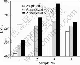
Fig. 9 Effect of annealing temperature on microhardness with different RE concentrations (1―0 g/L; 2―10 g/L; 3―15 g/L; 4―20 g/L)
4 Conclusions
1) 15 g/L nano-ceria particles can be pretreated into nanosuspension and homogeneously dispersed under ultrasonic field, displaying uniform distribution and oval shape in the composite coatings.
2) Polarization overpotential enhanced by fast duty cycle and pulse current characteristic is beneficial to increase deposition rate by modifying the concentration polarization.
3) During annealing at 600 ℃ for 2 h, RE addition can diffuse sufficiently with nickel matrix along the cracking gaps to remarkably improve microhardness.
References
[1] LI Jian-liang, XIONG Dang-sheng, HUANG Zhong-jia, KONG Jian, DAI Ji-hui. Effect of Ag and CeO2 on friction and wear properties of Ni-based composite at high temperature [J]. Wear, 2009, 267: 576-584.
[2] QU N S, ZHU D, CHAN K C. Fabrication of Ni-CeO2 nanocomposite by electrodeposition [J]. Scripta Mater, 2006, 54: 1421-1425.
[3] SEN R, BHATTACHARYA S, DAS S, DAS K. Effect of surfactant on the co-electrodeposition of the nano-sized ceria particle in the nickel matrix [J]. J Alloys Compd, 2010, 489: 650-685.
[4] LI L, ZHANG Y, DENG S, CHEN Y. Effect of ammonium on low temperature electrodeposition of Ni-P alloys [J]. Mater Lett, 2003, 57: 3444-3448.
[5] XU Rui-dong, WANG Jun-li, GUO Zhong-cheng, WANG Hua, High-temperature oxidation behavior of CeO2-SiO2/Ni-W-P composites [J]. Transactions of Nonferrous Metals Society of China, 2009, 19: 1190-1195.
[6] ZHANG Shi-hong, ZHANG Shi-hong, LI Ming-xi. Laser clad Ni-based alloy added nano-and micron-size CeO2 composites [J]. Opt Laser Technol, 2008, 40: 716-722.
[7] XUE Yu-jun, LIU Hong-bin, LAN Ming-ming, LI Ji-shun, LI Hang. Effect of different electrodeposition methods on oxidation resistance of Ni-CeO2 nanocomposite coating [J]. Surf Coat Technol, 2010, 204: 3539-3545.
[8] SEO M H, KIM J S, HWANG W S, KIM D J, HWANG S S, CHUN B S. Characteristics of Ni-P alloy electrodeposited from a sulfamate bath [J]. Surf Coat Technol, 2004, 176: 135-140.
[9] JIN Hui-ming, JIANG Shi-hang, ZHANG Lin-nan. Structural characterization and corrosive property of Ni-P/CeO2 composite coating [J]. J Rare Earths, 2009, 27: 109-113.
[10] SONG Yue-hai, WEI Gang, XIONG Rong-chun. Properties and structure of RE-Ni-W-SiC composite coating prepared by impulse electrodeposition [J]. Transactions of Nonferrous Metals Society of China, 2007, 17: 363-367.
[11] C?R?C G, BUND A, THIEMIG D. Electrocodeposition and characterization of cobalt lanthanide oxides composite coatings [J]. Surf Coat Technol, 2007, 202: 403-411.
[12] LI H, WANG L, CHEN H, DENG J F. Surface morphology and electronic state characterization of Ni-P amorphous alloy films [J]. J Nanocryst Solids, 2001, 281: 31-38.
[13] YANG L, PANG X, FOX-RABINOVICH G, VELDHUIS V, ZHITOMIRSKY I. Electrodeposition of cerium oxide films and composites [J]. Surf Coat Technol, 2011, 206: 1-7.
[14] ORDINE A P, D?AZ S L, MARGARIT I C P, BARCIA O E, MATTOS O R. Electrochemical study on Ni-P electrodeposition [J]. Electro Acta, 2006, 51: 1480-1486.
[15] FU Yen-pei, LIN Cheng-hsiung. Preparation of Y2O3-doped CeO2 nanopowders by microwave-induced combustion process [J]. J Alloys Compd, 2005, 389: 65-168.
[16] CHANG L M, GUO H F, AN M Z. Effect of Ce2(SO4)3 on structure and properties of Ni-Co/Al2O3 composite coating deposited by pulse reverse current method [J]. Appl Surf Sci, 2006, 253: 6085-6089.
[17] JIANG Li-long, YE Bing-huo, WEI Ke-mei. Effects of CeO2 on structure and properties of Ni-Mn-K/bauxite catalysts for water-gas shift reaction [J]. J Rare Earths, 2008, 26: 352-356.
[18] ZHOU Xiao-wei, JIN Hui-ming, ZHANG Lin-nan. Influence of pH value on microstructure and thermal stability of Ni-P electroless coating prepared in acidic condition [J]. Chin Chem Lett, 2009, 20: 845-848.
[19] CHANG L, KAO P W, CHEN C H. Strengthening mechanisms in electrodeposited Ni-P alloys with nanocrystalline grains [J]. Scripta Mater, 2007, 56: 713-716.
[20] BAHROLOLOOM M E, SANI R. The influence of pulse plating parameters on the hardness and wear resistance of nickel-alumina composite coatings [J]. Surf Coat Technol, 2005, 192: 154-163.
纳米稀土颗粒CeO2掺杂对Ni-P脉冲镀层
微观结构与沉积机理的影响
周小卫1,沈以赴1,靳惠明2,郑莹莹1
1. 南京航空航天大学 材料科学与技术学院,南京 210016;2. 扬州大学 机械工程学院,扬州 225127
摘 要:利用双脉冲电流特性与超声场高频振荡效应电沉积法制备Ni-P/n-CeO2 纳米复合镀层。借助环境扫描电镜 (E-SEM/EDXA)、透射电子显微镜 (TEM) 及X射线衍射仪 (XRD),对镀层微观形貌、化学成分及晶体结构进行分析。结果表明:掺杂15 g/L 纳米CeO2 (RE) 颗粒,稀土Ce含量与沉积速度分别可达2.3% 和68 μm/h,晶粒致密,呈现非晶态;在600 ℃下时效处理 2 h,复合镀层的显微硬度高达HV780。讨论了纳米稀土颗粒吸附特性与脉冲过电势对电沉积机理的影响。Ce4+ 或 n-CeO2 吸附在阴极活性表面形成大量具有催化作用的晶核,沉积并钉扎在开裂的纹裂源边缘。在高温时效时,纳米颗粒与部分Ni晶粒充分弥散互溶,占据空间,阻碍晶粒粗化及裂纹扩展,从而有效提高复合镀层的裂纹扩展抗力与显微硬度。
关键词:Ni-P镀层;脉冲电沉积;过电电势;沉积机理;CeO2
(Edited by LI Xiang-qun)
Foundation item: Project (CXLX12_0151) supported by Jiangsu Innovation program for Graduate Education and Fundamental Research Funds for Central Unibersities, China
Corresponding author: SHEN Yi-fu; Tel: +86-25-84896170; E-mail: Yifushen@nuaa.edu.cn
DOI: 10.1016/S1003-6326(11)61417-9

