J. Cent. South Univ. (2017) 24: 736-742
DOI: 10.1007/s11771-017-3475-z

A novel ice slurry producing system with vacuum freezing
TANG Yi-fang(唐艺芳)1, LIU Zhi-qiang(刘志强)1, 2, LIU Pei(刘佩)1, KANG Wei(康威)1
1. School of Energy Science and Engineering, Central South University, Changsha 410083, China;
2. Collaborative Innovation Center of Building Energy Conservation & Environmental Control,Zhuzhou 412007, China
 Central South University Press and Springer-Verlag Berlin Heidelberg 2017
Abstract: A novel vacuum ice slurry producing system with jet-pumps was proposed to deal with the problems of high energy consumption and ice blockage. In this novel system, one steam driven by a jet-pump was used to create vacuum in a hermetic vessel where water was sprayed through a nozzle to produce ice slurry, while the other steam was used to provide enough cold energy to make the left vapor in the hermetic vessel condense. Mathematical models of this novel system were established and theoretical simulation on the performance characteristics was also implemented based on the MATLAB program. Results show that the novel system is feasible and practicable, and the system performance is affected by many factors, such as the temperature of the generators, condensing temperature, evaporation temperature, and the cooling load of the refrigerator sub-system. The findings are helpful to improve the performance of ice slurry producing system.
Key words: ice slurry; vacuum freezing; ejector; solar energy
1 Introduction
Ice slurry is the mixture of ice particles and liquid solution. It has been used in many fields, e.g., refrigeration, food reserving and medical treatment. Recently, more attention has being attracted due to its flow and thermal characteristics and the environmental- friendly feature [1].
There are many ways to produce ice slurry including scraped-surface, orbital rod, fluidized bed, direct contact, sub-cooled water, vacuum method, etc. However, some economic and technical limitations exist [2, 3]. The scraped-surface method is widely used while it must be equipped with external motor-driven rotating blades. The rotor consumes a large amount of energy and the scrapers wear with time. The orbital rod method also uses moving parts, which is easy to be damaged. For the fluidized bed method, the main limitation is the maximum allowable temperature difference between the primary refrigerant and ice slurry, which enlarges the amount of ice crystals sticking on the tube wall, and the gradually thickening crystal layer deteriorates the effect of heat transfer. Besides, the fluidization velocity should be high enough; otherwise, the solid particles will not impact the inside heat exchanging walls and it will be hard to prevent build-up of an ice layer. The direct-contact method requires no mixture of water with the coolant. In such case, the proper refrigerants are limited and there exists a problem of separating water from the coolant to prevent clogging the coolant circuit. For the super-cold water method, the ice blockage is of a problem as super-cooled water may freeze inside the heat exchanger before contacting with the super-cooled state releaser. The vacuum ice slurry producing method is however, still under research and development. The saturation temperature of water varies with the change in the pressure. The pressure in the freezer is close to the triple-point of water, hence part of the water inside the freezer becomes water in low pressure and absorbs heat from the rest of that water, freezing the rest of the water [4-6]. Freezing occurs when the water droplets are falling (a large space exists), which can effectively prevent ice blockage. This method also has the advantages of simple device and high heat transfer rate due to the direct heat transition from latent heat of evaporation and solidification. However, the problem of high degree requirement of vacuum in the chamber is a concern. Nowadays, the mechanical vacuum pump is usually employed to maintain vacuum. Unfortunately, the mechanical-vacuum process is hurry for electric power and easy to wear. Besides, the suction of vapor makes it emulsified. To improve the vacuum freezing method, LI et al [7] proposed a new ice producing method where water is super-cooled to be evaporated in a low humidity. This proposal avoids the problem of ice blockage and the ice production is more reliable. ASAOKA et al [8, 9] investigated an alternative vacuum freezing method which produces ice slurry by evaporating ethanol solution instead of water. This system improves the ice forming stability and releases the high requirement for vacuum degree but still needs a large amount of energy.
In the present work, a novel ice slurry producing system is investigated which has been applied for patents [10]. The novel system is described and its mathematical model is built according to thermodynamic cycle analysis in the work. In addition, theoretical simulation studies on the performance characteristics are also investigated.
2 Novel vacuum ice slurry producing system
As shown in Fig. 1, the novel ice slurry producing system was composed of three working subsystems including ice slurry producing subsystem, conventional jet-pump refrigeration subsystem and jet-pump vacuum subsystem. The last two subsystems aimed to maintain the vacuum degree. Ejector has been taken into particular consideration as it improved fluid pressure without the consumption of mechanical energy and its structure was simple and reliable. It was possible to use low-grade thermal energy in an ejector, e.g., solar energy and waste heat [11, 12].
In the ice slurry producing subsystem, external water was pumped into the vacuum tank through the spray nozzle. Then, part of the water became vapor in low pressure, which absorbed the latent heat of vaporization from the rest water, freezing the rest of the water. Simultaneously, part of the vapor generated in the vacuum tank was condensed by jet-pump refrigeration subsystem, while the rest was extracted to the jet-pump vacuum subsystem to maintain the vacuum degree of the vacuum tank.
For the jet-pump refrigeration subsystem as shown in the left of Fig. 1, the condensation process of the vapor in the vacuum tank was realized by the following steps. The liquid refrigerant was boiled in the generator 1 at saturated pressure, and then the high temperature vapor entered into the steam ejector 1 and flowed through a convergent-divergent nozzle, where it expanded to supersonic flow and induced a low-pressure region at the nozzle exit [13]. The pressure difference produced by the driving fluid caused the suction of the refrigerant vapor from the modified evaporator that can condense the water vapor in the vacuum tank. After that, the two streams mixed in the mixing chamber and the mixed stream undergone shock waves in the constant section and its pressure was increased to a suitable condenser pressure in the diffuser. In the condenser, the mixed vapor was liquefied by cooling water to achieve the high thermal efficiency. Part of the resulting liquid refrigerant was pumped by feed pump to the generator 1, while the remaining liquid entered the modified evaporator after undergoing a pressure reduction in the expansion valve to complete the cycle.
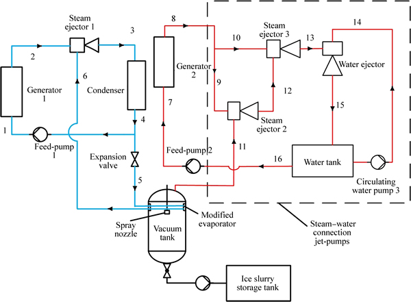
Fig. 1 Schematic of novel ice slurry producing system
For the jet-pump vacuum subsystem as shown in the right of Fig. 1, high-pressure steam was produced in the generator 2 at saturated pressure by absorbing heat (low-grade thermal energy can be used here). This steam flowed through a pipeline to the steam-water connection jet-pumps to entrain part of the vapor from the vacuum tank. Referring to the dashed rectangle in Fig. 1, the steam-water connection jet-pumps worked as follows: high-pressure steam from generator 2 was separated into two parts. The primary streams undergone adiabatic expansion through the convergent-divergent nozzle in the steam ejector 2 and steam ejector 3, respectively. At the same time, the vapor from the vacuum tank and the vapor from the steam ejector 2 outlet (the secondary stream) were entrained to each ejector. Both streams mixed in the mixing section of each ejector. The pressure of the mixed streams would be raised to intermediate pressure of the steam ejector 2 and steam ejector 3 in the diffuser section. Finally, the mixed stream at the exit of steam ejector 3 was entrained by water in water ejector. The mixed fluid flowed to the water tank which had an overflow. Correspondingly, the water in the tank was separated into two parts, one was pumped to the entrance of the water ejector as the working fluid and the rest was pumped to the generator to complete the sub-cycle.
To better understand the operation and the performance of the system, the following simulation was performed.
3 Models of ice slurry producing systems
Before numerical simulations, the coefficient of performance (COP) was theoretically analyzed, and the thermodynamic parameters of refrigerant used in the paper referred to NIST Refprop. All the energy and mass conservation equations were considered steady flows and only the mechanical or heat losses in the ejectors and pumps were considered [14].
3.1 Mathematical model of droplet in vacuum tank
As mentioned in Section 2, part of the water became vapor when the water was sprayed through the atomized nozzle (the rest became to ice). In this case, the energy balance equation will be Eq. (1) under the assumption that the vacuum tank undergone an adiabatic process.
 (1)
(1)
where c1 represents the specific heat of liquid water; cs represents the specific heat capacity of solid ice;  is the water mass flow sprayed into the vacuum tank;
  is the mass flow rate of the evaporated water in the vacuum tank; Δt1 is the difference in droplet temperature from initial temperature to the freezing temperature of subcooled water, set as 26 °C in the paper (supposing that the initial temperature was 20 °C and the freezing temperature was -6 °C as there was certain degree of supercooling when the water was freezed); Δt2 is the degree of supercooling, set as 6 °C in the paper.
The ice producing rate [5] is
 (2)
(2)
where  represents the mass flow rate of the produced ice.
3.2 Mathematical model of jet-pump refrigeration subsystem
Referring to Fig. 1, the energy balance equations of the jet-pump refrigeration subsystem under steady state conditions are as follows:
 (3)
(3)
 (4)
(4)
 (5)
(5)
 (6)
(6)
where ηm is the ratio of the shaft output power to the electrical input power (and the average efficiency of electric motors is 80%); ηp is the pump efficiency. The efficiency of the pump is usually 70% [14].
The mass balance is
 (7)
(7)
 (8)
(8)
 (9)
(9)
 (10)
(10)
where  represents the mass flow rate of water condensed by evaporator; μ1 is the entrainment ratio of the steam ejector 1.
Ejector entrainment ratio μ is defined as the ratio of the secondary mass flow rate to the primary counterpart. It depended on the operating temperature and pressure of the generator, the modified evaporator and the condenser. The current study calculated it through the method of SOKOLOW [15], which came from former Soviet Union and the method has been widely used in China. The model assumptions were: 1) the flow inside the ejector is one dimensional, steady and adiabatic; 2) the working fluid is an ideal gas with constant properties; 3) the pressure of the two fluids is constant during mixing process and they are completely mixed at the exit of the mixing chamber; 4) the irreversible factors, such as friction, boundary layer separation, shock wave interference, are characterized with speed coefficient and the mixing efficiency is within 0.8-1.0, depending on the operating conditions [15].
The method combines the conservations of momentum, energy and mass with the gas dynamic function model [15-18]. The gas dynamic function model links isentropic speed with the thermodynamic parameters of gas or vapor to simplify the calculation process.
3.3 Mathematical model of jet-pump vacuum subsystem
The energy balance equations of the jet-pump vacuum subsystem are
 (11)
(11)
 (12)
(12)
 (13)
(13)
The mass balance is
 (14)
(14)
 (15)
(15)
 (16)
(16)
 (17)
(17)
 (18)
(18)
Ejector entrainment ratio μ is
 (19)
(19)
 (20)
(20)
 (21)
(21)
The steam-water connection jet-pumps aimed to pump the low-pressure vapor extracted from the vacuum tank to the ambient pressure at water tank. This cannot be achieved by one ejector. The steam-water connection jet-pumps were composed of two steam ejectors and a water ejector. The steam-water connection jet-pumps can raise the pressure of the ejection fluid more effectively when compared with the steam jet-pumps. The entrainment ratio μ mainly depended on the operating temperature and pressure of the ejector’s inlet and outlet. Considering the principle of uniform distribution [16] and the conventional ejector compression ratio, one can find that p12/p11=p13/p12=4. This means the steam ejectors 2 and 3 increase the pressure of suction gas up to 4 times. One can then calculate the μ of each steam ejector. In the water ejector, the process was complex as the direct contact of the steam and water, resulting in the condensation of the vast majority of steam. A small amount of uncondensed steam and the non-condensable gas were mixed with the water and flew to the outlet. The entrainment ratio of the water ejector can be calculated via the laws of conservation of energy and mass as [17]
 (22)
(22)
Substitute Eq. (21) into Eq. (22) and rearranged as
 (23)
(23)
As depicted above, the function of the jet-pump refrigeration subsystem and jet-pump vacuum subsystem is to maintain the pressure inside the vacuum tank by condensing the vapor or extracting the vapor. Therefore,
 (24)
(24)
 (25)
(25)
where y represents the proportion of the vapor condensed which is also directly linked to the cooling load of the jet-pump refrigeration subsystem. In other words, the bigger the cooling load is, the more the vapor will be condensed in the vacuum tank.
3.4 Analysis of coefficient of system performance
The performance of the system was judged by COP [19]. COP is the ratio of the refrigerating effect to the energy input. In the current system, the heat absorption of evaporation was the refrigerating effect and therefore the COP is
 (26)
(26)
The system was driven by thermal energy Qg and mechanical energy Wp. To determine the quantity of each type of energy, the following COP was introduced [20].
 (27)
(27)
The performance characteristics of the system and the main influencing factors can then be investigated based on the above mathematical models.
4 Results and discussion
Generally, the operation temperature of a generator for an ejector refrigeration cycle or an ejector vacuum cycle is determined by heat source. In the current work, solar energy was the heat source in low-medium temperature field. Therefore, the collector lost more heat to the ambient and had lower efficiency at a higher operating temperature [21]. Consequently, the generator temperature of the jet-pump vacuum subsystem was in the range of 90-130 °C while the generator temperature of the jet-pump refrigeration subsystem was based on the critical temperature of the refrigerant. According to the Montreal Agreement, many commonly used refrigerants will be eliminated, such as R134a, R114. The thermophysical properties of refrigerants affect system performance. As a result, the selection of optimal refrigerant is significant. In this work, R290 was chosen as an example because its thermophysical properties can meet the need of the system. R290 does not have an effect on the ozone layer and has low global warming potential. Thus, the generator temperature of the jet- pump refrigeration subsystem can be chosen as 70-90 °C. The operating temperatures of evaporator and condenser were determined by the refrigeration purpose and climate. The condensing temperature was selected in the range of 25-45 °C, following the usual selection; The evaporation temperature was from -11 °C to -6 °C to condense the vapor in the vacuum tank. The constant parameters are listed in Table 1.
Table 1 Constant parameters of system
The calculations were performed with MATLAB. The thermodynamic properties of the refrigerants were cited from the REFPROP. The refrigerants used in the system were assumed to be saturated. The pressure drop of the system was negligible.
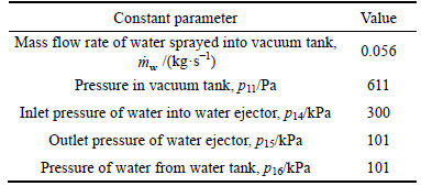
Figure 2 shows the effect of y on the value of COP and COPw at te1=-6 °C, tc1=30 °C, tg1=90 °C and tg2=120 °C. It can be seen from Fig. 2 that the COP of the system is almost the same, decreasing from 0.114 to 0.1114 when y increases from 0 to 1. On the contrary, the COPw of the system decreases from 24.95 to 4.29. This is because the heat transfer of the generators is the main part of the energy consumption when the COP is considered. The heat transfer of the generator 1 increases with the increase in y. The growing rate is higher than the dropping rate of the heat transfer of generator 2. When the COPw is considered, the pumps become the main part of energy consumption. The work of the feed pump 1 increases significantly with the increase in y. The growing rate of the work is higher than the dropping rate of the sum feed pump 2 plus water pump 3. It shows that the refrigeration subsystem adds operating cost to the whole system without increasing its performance in Fig. 2. However, the increase in ice producing is due to the fact that the vapor is condensed to ice via the refrigeration subsystem.
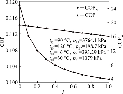
Fig. 2 Effect of proportion of vapor condensed y on COP and COPw
The temperatures tg1 and tg2 of the generator of the jet-pump refrigeration subsystem and the jet-pump vacuum subsystem are independent. Operating parameters play an important role in affecting the performance. Figure 3 gives the variations in COP and COPw of the system with tg1. It demonstrates that an increase in the generator temperature tg1 from 70 to 90 °C leads to the increase in the COP from 0.0748 to 0.1128, while the COPw increases firstly from 6.285 to 7.073 when the generator temperature tg1 increases from 70 to 80 °C, and then it drops from 7.073 to 6.794 as the generator temperature tg1 increases from 80 °C to 90 °C. The increase in COP is mainly due to the fact that the entrainment ratio μ1 increases with the increase in the generator temperature tg1. In such case, it requires less high-pressure vapor to pump the same amount of low-pressure vapor. Although the work of the feed pump 1 increases, it does not overweigh the decrease in heat transfer. Considering the COPw, the main energy consumption is the pump work. The work of the feed-pump 1 accounts for a large part of the whole energy consumption as it has high pressure difference and low density. The variation in the COPw is mainly due to the change in the work of feed-pump 1.
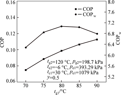
Fig. 3 Effect of generator temperature tg1 on COP and COPw
As shown in Fig. 4, both COP and COPw increase with the increase in the generator temperature tg2, which is due to the increase in the generator temperature tg2, therefore increasing the values of the entrainment ratios μ2 and μ3. Consequently, to compress the same amount of low-pressure vapor, less high-pressure vapor is required, resulting in the decrease in the heat transfer of generator Q2 and the work of the circulating water pump.
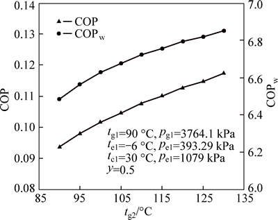
Fig. 4 Effect of generator temperature tg2 on COP and COPw
Figure 5 shows the variations in the COP and COPw with different condensing temperature tc1. Figure 5 illustrates that the condensing temperature affects the COP and COPw as well. The COP decreases from 0.1361 to 0.0257 as the condensing temperature increases from 25 to 45 °C while the COPw decreases from 9.676 to 0.995. This is because the raised condensing temperature decreases the value of the entrainment ratio μ1. As a result, to compress the same amount of the low-pressure vapor, more high-pressure vapor is needed, resulting in the increase in the heat transfer of the generator Q1 and the work of the feed pump 1.
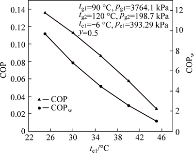
Fig. 5 Effect of condensing temperature tc1 on COP and COPw
Figure 6 shows the variations in the COP and COPw with different evaporation temperature te1. As shown in Fig. 6, better system performance is generally obtained at higher evaporation temperatures. This is because the higher the evaporation temperature is, the bigger the entrainment ratio is. Therefore, to eject the same amount of vapor (secondary stream), less high-pressure vapor (primary stream) is required, resulting in the decrease in the heat transfer of the generator 1 and the work of the feed-pump 1.
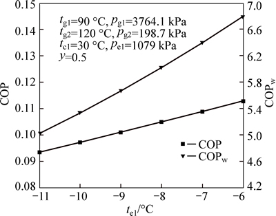
Fig. 6 Effect of evaporation temperature te1 on COP and COPw
5 Conclusions
1) A novel vacuum ice slurry producing system is presented. In this novel system, the vacuum degree is maintained by the jet-pump refrigeration subsystem and jet-pump vacuum subsystem through extracting the vapor and condensing the vapor, respectively. In such way, the freezing process occurs in the scope of large space. As a result, the problem of ice blockage can be avoided. The performance of the system is improved due to the direct heat transfer of the solidification latent heat and evaporation latent heat.
2) The mathematical model of the vacuum ice slurry producing system with refrigerant R290 was presented and the theoretical analysis of the system performance characteristics was conducted. Results show that the system performance is affected by many factors, like the temperature of the generators, condensing temperature, evaporation temperature, and the cooling load of the refrigerator sub-system. The findings are helpful to improve the system performance. The experimental study of the system will be carried out in the near future.
Acknowledgement
This work was supported by National Natural Science Foundation of China (NSFC) under the grant No. 51376198 and Hunan Provincial Natural Science Foundation of China (11JJ22029). The authors also gratefully acknowledge the Collaborative Innovation Center of Building Energy Conservation & Environmental Control, China.
References
[1] ZHANG Xue-jun, QIU Li-ming, ZHANG Peng. Performance improvement of vertical ice slurry generator by using bubbling device [J]. Energy Conversion and Management, 2008, 49(1): 83-88.
[2] KAUFFELD M, KAWAJI M, EGOLF W P. Handbook on ice slurries [M]. Paris: International Institute of Refrigeration, 2005.
[3] ZHANG Peng, MA Zhi-wei. An overview of fundamental studies and applications of phase change material slurries to secondary loop refrigeration and air conditioning systems [J]. Renewable & Sustainable Energy Reviews, 2012, 16(7): 5021-5058.
[4] JIN Cong-zhuo, ZHAO Lian-jin, MA Teng-yue, CHENG Wen-long, YI Guang-jiang. Theoretical analysis of ice slurry production by water spray evaporation method [J]. Fluid Machinery, 2011, 39(5): 61-65.
[5] SHIN H T, LEE Y P, JURNG J. Spherical shaped ice partical production by spraying water in a vacuum chamber [J]. Applied Thermal Engineering, 2000, 20: 439-454.
[6] EAMES I W, WORALL M, WU S. An experimental investigation into the integration of a jet-pump refrigeration cycle and a novel jet-spay thermal ice storage system [J]. Applied Thermal Engineering, 2013, 53(2): 285-290.
[7] LI Xiu-wei, ZHANG Xiao-song, CAO Rong-quan, FU Xiu-zhang. A novel ice slurry producing system: Producing ice by utilizing inner waste heat [J]. Energy Conversion and Management, 2009, 50(12): 2893-2904.
[8] ASAOKA T, SAITO A, OKAWA S, KUMANO H, HOZUMI T. Vacuum freezing type ice slurry production using ethanol solution 2nd report: Investigation on evaporation characteristics of ice slurry in ice production [J]. International Journal of Refrigeration, 2009, 32(3): 394-401.
[9] ASAOKA T, SAITO A, OKAWA S, ITO T, LIUMI N. Vacuum freezing type ice slurry production using ethanol solution 1st report: Measurement of vapor-liquid equilibrium data of ethanol solution at 20 °C and at the freezing temperature [J]. International Journal Of Refrigeration, 2009, 32(3): 387-393.
[10] LIU Zhi-qiang, LIU Pei, LV Yuan-yuan. A novel ice slurry production system of vacuum freezing type: CN, ZL20132 0123086.2[P]. 2015-02-18. (in Chinese)
[11] YAN Jia, CAI Wen-jian. Area ratio effects to the performance of air-cooled ejector refrigeration cycle with R134a refrigerant [J]. Energy Conversion and Management, 2012, 53(1): 240-246.
[12] GRAZZINI G, MILAZZO A, PAGANINI D. Design of an ejector cycle refrigeration system [J]. Energy Conversion and Management, 2012, 54(1): 38-46.
[13] KHALIL A, FATOUH M, ELGENDY E. Ejector design and theoretical study of R134a ejector refrigeration cycle [J]. International Journal of Refrigeration, 2011, 34(7): 1684-1698.
[14] JARUWONGWITTAYA T, CHEN G. Application of two stage ejector cooling system in a bus [J]. Energy Procedia, 2012, 14: 187-197.
[15] SOKOLOW E R, ZINGER H M. Jet devices injector [M]. HUANG Qiu-yun, trans. Beijing: Science Press, 1977. (in Chinese)
[16] PENG Wang-ming. Research on the solar energy air-cooled ejection refrigeration System [D]. Changsha: Central South University, 2009. (in Chinese)
[17] WANG Wei-hui. Design and application of a steam-water ejector mixer [J]. Fluid Machinery, 2007, 35(2): 26-28.
[18] PAN Jin-shan, SHAN Peng. Fundamentals of gas dynamics [M]. Beijing: National Defence Industry Press, 2012. (in Chinese)
[19] PRIDASAWAS W, LUNDQVIST P. An exergy analysis of a solar-driven ejector refrigeration system [J]. Solar Energy, 2004, 76: 369-379.
[20] YU Jian-lin, DU Zhen-xing. Theoretical study of a transcritical ejector refrigeration cycle with refrigerant R143a [J]. Renewable Energy, 2010, 35(9): 2034-2039.
[21] HUANG B J, PETRAKOS V A, SAMOFATOU Y I, SHCHETININ N A. Collector selection for solar ejector cooling system [J]. Solar Energy, 2001, 71(4): 269-274.
(Edited by YANG Hua)
Cite this article as: TANG Yi-fang, LIU Zhi-qiang, LIU Pei, KANG Wei. A novel ice slurry producing system with vacuum freezing [J]. Journal of Central South University, 2017, 24(3): 736-742. DOI: 10.1007/s11771-017-3475-z.
Foundation item: Project(51376198) supported by the National Natural Science Foundation of China; Project(11JJ22029) supported by the Hunan Provincial Natural Science Foundation of China
Received date: 2015-08-31; Accepted date: 2016-01-16
Corresponding author: LIU Zhi-qiang, PhD, Professor; Tel: +86-731-88879863; E-mail: liuzq@csu.edu.cn

