Trans. Nonferrous Met. Soc. China 24(2014) 1800-1806
Microstructure and cutting performance of CrTiAlN coating for high-speed dry milling
Li LU1, Qi-min WANG1, Bing-zhou CHEN2, Yong-cui AO1, Dong-hai YU1, Cheng-yong WANG1, Shang-hua WU1, Kwang Ho KIM3
1. School of Electromechanical Engineering, Guangdong University of Technology, Guangzhou 510006, China;
2. Kunshan Kedun Nano Coatings Tech. Co. Ltd., Suzhou 215000, China;
3. National Core Research Center for Hybrid Materials Solution, Pusan National University, Busan 609735, Korea
Received 24 July 2013; accepted 5 November 2013
Abstract: Using a closed field unbalanced magnetron sputtering system, the cemented carbide end mills were coated with a CrTiAlN hard coating, which consisted of a Cr adhesive layer, a CrN interlayer and a CrTiAlN top layer. The microstructure and mechanical properties of the coating were investigated by X-ray diffraction (XRD), scanning electron microscopy (SEM), transmission electron microscopy (TEM), micro indentation and scratch test. The cutting performance of the coated end mills were conducted by high-speed dry milling hardened steel (P20, HRC 45). The results indicates that the coating is composed of (Cr,Ti,Al)N columnar grains with nanolayers. The coating exhibits good adhesion to cemented carbide substrate and high microhardness of around 30 GPa. The coated end mills show significant improvement on tool life and much lower cutting force as compared to the uncoated ones. And the related mechanisms were discussed.
Key words: CrTiAlN coating; high-speed machining; hardened steel; tool wear
1 Introduction
Nowadays high-speed and dry machining materials at hardened state increasingly becomes important in manufacturing industry due to its advantages, such as high productivity, cost reduction, and environmental waste elimination [1,2]. In high-speed and dry machining operations, due to high cutting temperatures and high stresses on the cutting edges [3], tool life is greatly shortened because of rapid tool wear, especially the hard machining difficult-to-cut materials, such as hardened steels, titanium alloys and superalloys [4-6]. The application of single and multilayer nitride coatings on carbide cutting tools has led to the significant increase of tool life in machining processes [7]. Various hard coatings on cutting tools have been developed to meet the requirements of hardness, chemical inertness, wear resistance, and oxidation resistance [8].
As one conventional hard coating, CrN coating is popularly used for its low friction coefficient, high toughness, and good oxidation and corrosion resistance. However, CrN coating is mainly limited to tribological applications on machine parts due to its relatively low hardness. Recently, CrN-based coatings with additions of elements such as Al [9], Si [10], B [11], C [12], have been actively investigated to improve the properties of CrN binary coating. Among these coatings, CrTiAlN coatings exhibit excellent combinations of high hardness, good toughness, and excellent wear resistance [13]. The coatings were successfully fabricated by magnetron sputtering or cathodic arc evaporation techniques on various substrates, and were reported to improve the tribological property of Mg alloy and AISI 304 stainless steel [8,14], enhance corrosion and wear resistance of titanium alloys [15], and to improve cutting performance of the high speed steel drills during dry drilling processes [16]. By considering the good properties of the CrTiAlN coatings, they have high potential to be applied on the carbide cutting tools for high speed milling. However, it seems that little work has been reported on this topic.
In this work, a closed field unbalanced magnetron deposition system was used, and the carbide end mills were coated with a CrTiAlN hard coating. The microstructure, properties of the coating and the cutting performance of the coated end mills were studied. The performance of CrTiAlN coating for high-speed dry milling was discussed.
2 Experimental
2.1 Coating deposition and evaluation
The CrTiAlN coating was deposited using a closed field unbalanced magnetron sputtering system (Teer UDP850, as shown in Fig. 1) with four metal targets (two Cr targets placed symmetrically, one Al target and one Ti target) installed on four sides of the chamber wall. The substrates utilized in this study included (100) single crystalline Si wafers (for microstructure analysis), mirror-polished SUS304 stainless steel plates (for Rockwell C indentation test and friction coefficient measurements), cemented carbide plates (for scratch test) and cemented carbide end mills (for cutting test), respectively. Before coating deposition, the substrates were degreased and ultrasonically cleaned in acetone and ethanol solutions and dried by filtrated compressive air. Then the substrates including cemented carbide end mills were loaded on a substrate holder. The substrate holder was rotating with speed of 3 r/min. During coating deposition, Ar gas (99.999%) with flux rate of 30 mL/min was introduced into the sputter target holder to increase the sputtering rate. The N2 gas (99.999%) was injected near the substrate holder using an optical emission monitor (OEM) with feedback system. The substrates were cleaned by ion bombardment using plasma of low sputtering current under Ar atmosphere, followed by the deposition of a Cr adhesive layer, a CrN interlayer, and a CrTiAlN top layer. The deposition parameters are listed in Table 1. The base pressure was 4.0×10⁻³ Pa. The chamber deposition pressure and substrate temperature during deposition were set as 10×10-1 Pa and 300 °C, respectively. For all the sputtering sources, pulsed powers with frequency of 250 kHz were utilized. The thicknesses of the individual layers were controlled as 0.4, 0.6, and 2.1 μm for the Cr, CrN, and CrTiAlN layer, respectively, by controlling the deposition time.
The phase structure of the as-deposited coatings was characterized by X-ray diffraction (D8 Advance Brucker, Cu Kα) with diffraction angles 2θ between 30° and 80°. The morphologies and chemical compositions of the coatings were observed and determined by scanning electron microscope (SEM, Hitachi, S3400N) equipped with an energy-dispersive X-ray spectrometer (EDX). Structural information of the coating was analyzed by transmission electron microscope (TEM, FEI, Tecnai G2 F20 S-Twin) with a 200 kV acceleration voltage. The average friction coefficient was evaluated through sliding tests using a conventional ball-on-disc wear apparatus (MMU-5G). A steel ball (diameter of 5 mm, HV0.2 of 700) was used as the counterpart material. Adhesion and coating toughness were evaluated by the Rockwell C indentation method (tip radius of 0.2 mm, applied load of 1470 N) and scratch test (CSM, Revetest scratch tester). Hardness measurements were performed using a HXD-10000TM/LCD microhardness tester with a diamond Vickers indenter under a load of 0.49 N.
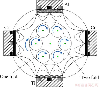
Fig. 1 Schematic setup of closed field magnetron sputtering machine
2.2 Milling tests
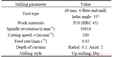
The cemented carbide end mills (type GM-4E-D6.0S, average WC grain size of 0.8 μm) with and without CrTiAlN coatings were tested in a vertical high speed machining center (DMU 60T) with the milling parameters listed in Table 2. The cutting force was measured and recorded by a Kistler 9265B three- dimensional force measurement platform. The machining process was paused at each interval milling length of 2.6 m to measure the flank wear of peripheral edge under a stereo optical microscope (OLYMPUS, SZ61TRC) with a CCD camera. In order to maintain the position precision and continuity of the experiment, the tool holder was directly detached from the main spindle in each interval to do the test. Flank wear was obtained by averaging three values on the cutting edge within axial depth of cut. The tool life obtained with flank wear threshold of 0.2 mm was used as a criterion (ISO 3002/1) for a comparative evaluation of the coating performance [17].
Table 1 Deposition parameters of CrAlTiN coating
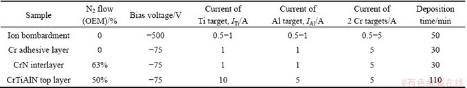
Table 2 Milling parameters for tool performance tests
3 Results and discussion
3.1 Characterization of CrTiAlN coating layers
Figure 2 shows the surface and cross-sectional SEM images of the CrTiAlN coating in this study. A smooth surface can be observed on the coating surface. The coating consists of three layers: 1) Cr interlayer with thickness of ~0.4 μm at the coating-substrate interface; 2) CrN interlayer with thickness of ~0.6 μm on top of the Cr layer; and 3) CrTiAlN layer with thickness of ~2.1 μm on the top of the coatings. The CrTiAlN top layer exhibits apparent columnar microstructure. The densely packed columns with diameter of ~0.1-0.2 μm can be observed both from the cross section image in Fig. 2(b) and from the corresponding surface particles in Fig. 2(a), which correspond to the domes of columns. The chemical composition is identified as: 36.22% Cr, 8.57% Ti, 5.99% Al, and 49.22% N (mole fraction) by EDX analysis.
The XRD pattern of the CrTiAlN coating is shown in Fig. 3. The diffraction peaks are identified as TiN and CrN FCC phases. The two peaks between 35° and 45° are close to TiN (111) and CrN (200), respectively. No hexagonal AlN peak is observed. Therefore, it can be concluded that CrTiAlN coating is composed of FCC- (Ti, Cr, Al)N phase of B1-NaCl (rock salt) structure, where Ti and Al solid solutionized into the CrN phase by substituting the position of Cr atoms. The shift of (111) and (200) peaks is because of the different radius of Ti and Cr atoms. This result is in agreement with the work by other research groups [18,19].
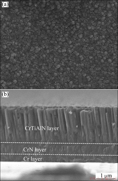
Fig. 2 SEM images of surface (a) and cross-section (b) of CrTiAlN coating
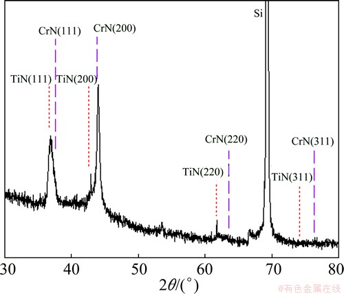
Fig. 3 XRD spectra of as-deposited CrTiAlN coating
To further investigate the coating microstructure, the CrTiAlN coating of top layer was analyzed by cross-sectional TEM observations. The cross sectional TEM images and the selected area electron diffraction (SAED) pattern are shown in Fig. 4. Corresponding to SEM observations in Fig. 2, the coating exhibits columnar microstructure with column width of 50-100 nm. On high magnifications (Figs. 4(b) and (c)), it can be detected that the columns are composed of nanolayers with thickness of several nanometers. The formation of nano multilayer structure is due to the substrate rotation during coating deposition. In the deposition process, the substrates successively pass Cr, Ti, Cr, Al targets in one cycle. When the substrates are close to one target, the metallic species will fly to the specimens and grow corresponding nitride on the surface. Correspondingly, the multilayered microstructure forms in the coatings. Because of the 2-dimensional rotation, the thicknesses of the nano layers in different columns are not uniform, varying from 2-3 nm to 4-6 nm. From the SAED pattern in the insert of Fig. 4(a), the diffraction spots are mainly indexed to FCC structure of CrN phase with (111), (200), (220) and (311) diffractions. Weak diffraction patterns corresponding to the TiN phase are also detected. The coating is mainly composed of CrN phase with solid solution of Al and Ti elements.
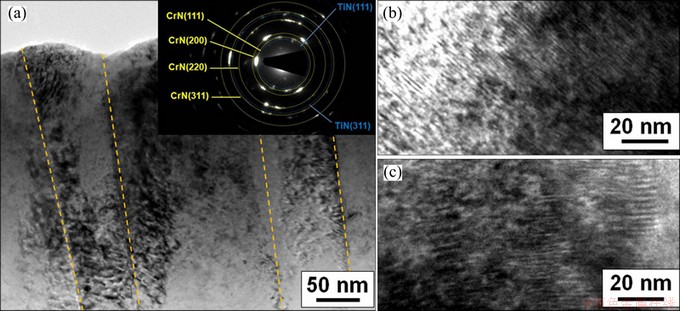
Fig. 4 Cross-sectional TEM image of CrTiAIN coating with corresponding SAED pattern (a), and high-resolution TEM images (b) and (c)
Table 3 lists the mechanical properties of the CrTiAlN coating. Hardness is an important property of coatings for cutting tool applications. In this study, the CrTiAlN coating shows the high hardness around 30 GPa, much higher than that of the CrN coating. The improved hardness should be due to the solid-solution hardening by the addition of Ti and Al elements in the CrN crystals. The nanolayered microstructure should also contribute to the hardening of the coating. The wear property of the coating is measured by ball-on-disc wear test. The average friction coefficient of the coating against hardened steel ball is 0.55 which is apparently lower as compared to that of the bare cemented carbide (about 0.78). This is the value similar to other studies [8].
Adhesion and coating toughness is evaluated by the scratch test and Rockwell C indentation method (tip radius of 0.2 mm, applied load of 1470 N) [20]. As shown in Fig. 5(a), in the indented coatings, no sign of spalling or adhesion failures is found. The coating adhesion can be identified as HF1 according to the defined adhesion strength quality (ASQ) criterion. According to the scratch test result, the critical load is more than 60 N. As shown in Fig. 5(b), no delamination and cracks of the coating are detected. The coating exhibits excellent adhesion on the substrate.
Table 3 Mechanical properties of as-deposited CrTiAlN coating

3.2 Cutting performance
The cutting performance of uncoated and CrTiAlN coated end mills is compared by milling a hardened steel P20 (HRC 45) in high-speed dry cutting conditions. Figure 6 shows the flank wear values as a function of cutting length for uncoated and coated end mills. As the cutting length increases, the flank wear increases accordingly. The wear curve of the CrTiAlN coated end mills increases more slightly as compared to the uncoated one. The flank wear of the bare end mill is more than 200 μm at cutting length of 10.4 m. At the same cutting length, the coated one exhibits the flank wear value of only 68 μm. The CrTiAlN coating can significantly improve the cutting performance of cemented carbide end mills, reduce flank wear and extend tool life. The wear morphologies of two cutting tools at a cutting length of 10.4 m are shown in Fig. 7. Serious flank wear of uncoated tool was found in Fig. 7(a). Considering the same cutting length, the CrAlTiN coated end mill is much less wear than the uncoated one.

Fig. 5 Coated surface after Rockwell C adhesion test (a) and scratch test (b)
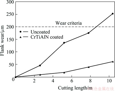
Fig. 6 Flank wear as function of cutting length
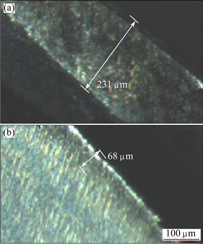
Fig. 7 Wear morphologies of worn uncoated tool (a) and coated end mills (b) at cutting length of 10.4 m
Figure 8 shows the average cutting force F as a function of cutting length. Here the average cutting force F is calculated by the principal force Fx, the thrust force Fy and axial force Fz with the formula F=(Fx2+Fy2+Fz2)1/2 . As shown in Fig. 8, with the increase of cutting distance, the cutting forces of uncoated tool increase apparently. The cutting force for the CrTiAlN coated end mill is much lower than that of the uncoated one and remains almost unchanged during the cutting process. Evidently, the coating reduces the cutting force of the end mills. During milling tests, the uncoated tool exhibits a cacophony of mechanical noise with sparking chips splashing out, which reveals high temperature at the cutting edge. Comparatively, the coated tool shows a stable milling process with darker chips indicating lower cutting temperature. The low friction coefficient of CrTiAlN coating is the reason for the low cutting force and stable milling process. CrTiAlN coating can diminish the mechanical stress among tool and chips, so as to make the chips run out more smoothly. As a result, cutting forces and flank wear as a function of the cutting length are considerably lowered by application of CrTiAlN coatings in high-speed milling.

Fig. 8 Variation of cutting force as function of cutting length during milling test
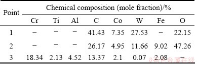
In order to further understand the wear mechanism, SEM observations and local chemical analysis were performed on the flank edge of the end mills with and without coating after milling tests. Corresponding to the SEM observations in Fig. 9, the uncoated one exhibits much wider flank wear on the cutting edges. For the uncoated tool, the EDX results in Table 4 show that the content of W, C and Co in the cutting area 2 is much lower than that in the uncontact area 1, which indicates loss of hard WC phase. Meanwhile, the Fe content (main constituent of hardened steel) in the cutting area increases significantly, which means the transfer of materials from the workpiece to the cutting edge. Another important phenomenon to be noted is that high concentration of oxygen on the worn surface of the uncoated tool is detected by EDX. It demonstrates that the oxidation takes place on the cutting edge under high cutting temperature. Therefore, the failure of uncoated end mill is a result of loss of hard WC phase, cold welding of machined material, and oxidation of cutting edge. As the milling progresses, the strength of cutting edge decreases, leading to enhanced attrition and worn on the cutting edge [21]. The adhered or welded work material will be hit and squashed by the tool on re-entry into the workpiece, thus leading to the initiation of chipping and finally to the breakage of carbide at the cutting edge. The worn cutting edge induces higher friction, load and temperature, which results in further wear, chipping, and failure of milling tools [22]. For the coated tool, chemical analysis on the cutting edge (Area 3) of coated end mills shows that mainly Ti, Al, Cr and N (elements of coating) with low fraction of W and Co (elements of cemented carbide) are found at the wear area of the cutting edge. It indicates that the CrTiAlN coating does not run out off and shows a good wear resistance although some cemented carbide is exposed after the milling test. Less Fe at the worn surface of coated tool reveals that CrTiAlN coating reduces the adhesive wear at the contact area in the complex terrible conditions to some extent. The lower adhesive wear for the coated tool can be attributed to the decreased cutting force due to lower friction coefficient and better oxidation resistance of the coating than those of the WC-Co substrate. Therefore, it can be concluded that the CrTiAlN coating improves the cutting performance of the end mills by diminishing cutting forces, lowering the temperatures, and reducing the adhesive wear on the cutting edges.
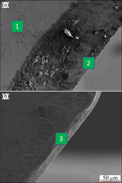
Fig. 9 Local chemical analysis on flank of uncoated (a) and CrTiAlN coated (b) end mills after milling test
Table 4 Chemical compositions of corresponding points in Fig. 9
4 Conclusions
1) CrTiAlN hard coating with Cr and CrN interlayers was deposited on Si wafers and cemented carbide end mills using a closed field unbalanced magnetron deposition system.
2) The CrTiAlN coating exhibits a dense columnar crystal structure with columns consisting of nanolayers. The formation of nano-layered structure is due to the substrate rotation in front of Cr, Ti, and Al targets during coating deposition.
3) The CrTiAlN coating shows good mechanical properties such as high hardness (30 GPa), good adhesive strength (>60 N), and low friction coefficient (about 0.55). Due to the excellent mechanical properties of CrTiAlN coating, it can significantly improve the cutting performance of cemented carbide end mills in high-speed milling hardened steel. The main merits of the coating lie in that the coating diminishes cutting forces, lowers the temperatures on the cutting edge, and reduces the adhesive wear on the cutting edges.
References
[1] GRZESIK W. Advanced machining processes of metallic materials: Theory, modeling and applications [M]. Netherlands: Elsevier, 2008.
[2] EL HAKIM M A, ABAD M D, ABDELHAMEED M M, SHALABY M A, VELDHUIS S C. Wear behavior of some cutting tool materials in hard turning of HSS [J]. Tribology International, 2011, 44: 1174-1181.
[3] NING Y, RAHMAN M, WONG Y S. Investigation of chip formation in high speed end milling [J]. Journal of Materials Processing Technology, 2001, 113: 360-367.
[4] JUAN H, YU S F, LEE B Y. The optimal cutting-parameter selection of production cost in HSM for SKD61 tool steels [J]. International Journal of Machine Tools & Manufacture, 2003, 43: 679-686.
[5] YAO C F, WU D X, JIN Q C, HUANG X C, REN J X, ZHANG D H. Influence of high-speed milling parameter on 3D surface topography and fatigue behavior of TB6 titanium alloy [J]. Transactions of Nonferrous Metals Society of China, 2013, 23: 650-660.
[6] AXINTE D A, DEWES R C, MATER J. Surface integrity of hot work tool steel after high speed milling-experimental data and empirical models [J]. Journal of Materials Processing Technology, 2002, 127: 325-335.
[7] BIROL Y, ISLER D. AlTiN and AlTiON-coated hot work tool steels for tooling in steel thixoforming [J]. Transactions of Nonferrous Metals Society of China, 2010, 20: s1022-s1028.
[8] HSU C H, CHEN K L, LIN Z H, SU C Y, LIN C K. Bias effects on the tribological behavior of cathodic arc evaporated CrTiAlN coatings on AISI 304 stainless steel [J]. Thin Solid Films, 2010, 518: 3825-3829.
[9] LI P, CHEN L,WANG S Q, YANG B, DU Y, LI J, WU M J. Microstructure, mechanical and thermal properties of TiAlN/CrAlN multilayer coatings [J]. International Journal of Refractory Metals and Hard Materials, 2013, 40: 51-57.
[10] KANG M S, WANG T G, SHIN J H, NOWAK R, KIM K H. Synthesis and properties of Cr-Al-Si-N films deposited by hybrid coating system with high power impulse magnetron sputtering (HIPIMS) and DC pulse sputtering [J]. Transactions of Nonferrous Metals Society of China, 2012, 22: s729-s734.
[11] ROTHER B, KAPPL H. Effects of low boron concentrations on the thermal stability of hard coatings [J]. Surface and Coatings Technology, 1997, 96: 163-168.
[12] LACKNER J M, WALDHAUSER W, EBNER R, BAKKER R J,  T, MAJOR B. Room temperature pulsed laser deposited (Ti, Al)CxN1-x coatings―Chemical, structural, mechanical and tribological properties [J].Thin Solid Films, 2004, 468: 125-133.
[13]  Industrial applications of CrN (PVD) coatings, deposited at high and low temperatures [J]. Surface and Coatings Technology, 1997, 97: 182-191.
[14] SHI Y J, LONG S Y, YANG S C, PAN F S. Structural and tribological properties of CrTiAlN coatings on Mg alloy by closed-field unbalanced magnetron sputtering ion plating [J]. Applied Surface Science, 2008, 254: 7342-7350.
[15] WANG Y M, JIANG B L, GUO L X, LEI T Q. Tribological behavior of microarc oxidation coatings formed on titanium alloys against steel in dry and solid lubrication sliding [J]. Applied Surface Science, 2006, 252: 2989-2998.
[16] BAI L J, ZHU X D, XIAO J M, HE J W. Study on thermal stability of CrTiAlN coating for dry drilling [J]. Surface and Coatings Technology, 2007, 201: 5257-5260.
[17] D’ERRICO G E, GUGLIELMI E, RUTELLI G, MATER J. A study of coatings for end mills in high speed metal cutting [J]. Journal of Materials Processing Technology, 1999, 92-93: 251-256.
[18] EZURAA H, ICHIJOA K, HASEGAWAB H, YAMAMOTOC K, HOTTA A. SUZUKI T. Micro-hardness, microstructures and thermal stability of (Ti,Cr,Al,Si)N films deposited by cathodic arc method [J]. Vacuum, 2008, 82: 476-481.
[19] HUANG F, WEI G, BARNARD J A, WEAVER M L. Nanotribology studies of Cr, Cr2N and CrN thin films using constant and ramped load nanoscratch techniques [J]. Surface and Coatings Technology, 2001, 146-147: 357-362.
[20] HEINKE W, LEYLAND A, MATTHEWS A. Evaluation of PVD nitride coatings, using impact, scratch and Rockwell-c adhesion test [J]. Thin Solid Films, 1995, 270: 431-438.
[21] JAWAID A, SHARIF S, KOKSAL S. Evaluation of wear mechanisms of coated carbide tools when face milling titanium alloy [J]. Journal of Materials Processing Technology, 2000, 99: 266-274.
[22] TRENT E M, WRIGHT P K. Metal Cutting [M]. Netherlands: Elsevier, 2000.
CrTiAlN涂层的显微组织及其在高速干铣削中的切削性能
鲁 力1,王启民1,陈柄洲2,敖永翠1,余东海1,王成勇1,伍尚华1,Kwang Ho KIM3
1. 广东工业大学 机电工程学院,广州 510006;
2. 昆山克顿纳米镀层科技有限公司,苏州 215000;
3. National Core Research Center for Hybrid Materials Solution, Pusan National University, Busan 609735, Korea
摘 要:利用闭合场非平衡磁控溅射系统制备CrTiAlN 复合涂层硬质合金立铣刀,该涂层由Cr粘接层、CrN过渡层以及CrTiAlN涂层组成。采用X 射线衍射(XRD)、扫描电子显微镜(SEM)、透射电镜、显微硬度、划痕仪等技术对CrTiAlN 涂层的显微组织和力学性能进行分析表征。在干式切削条件下,通过高速铣削测试淬硬钢(P20,HRC45)的切削性能。结果表明:涂层由有着纳米层Cr(Ti,Al)N结构的柱状晶组成。CrTiAlN涂层在硬质合金上具有良好的结合性能以及近30 GPa的高硬度。相对于无涂层铣刀,涂层大大提高硬质合金立铣刀寿命、减小切削力。讨论其相关切削机理。
关键词:CrTiAlN涂层;高速加工;淬硬钢;刀具磨损
(Edited by Chao WANG)
Foundation item: Projects (500120069, U1201245) supported by the National Natural Science Foundation of China;Project (2011J2200036) supported by Guangzhou Scientific and Technological Planning Project, China; Project supported by Guangdong Province Universities and Colleges Pearl River Scholar Funded Scheme (2012), China
Corresponding author: Qi-min WANG; Tel/Fax: +86-13802729261; E-mail: qmwang@gdut.edu.cn
DOI: 10.1016/S1003-6326(14)63256-8

