J. Cent. South Univ. Technol. (2008) 15: 285-288
DOI: 10.1007/s11771-008-0053-4

3D cavity detection technique and its application based on cavity auto scanning laser system
LIU Xi-ling(刘希灵)1, LI Xi-bing(李夕兵) 1, LI Fa-ben(李发本)2,
ZHAO Guo-yan(赵国彦)1, QIN Yu-hui(秦豫辉)2
(1. School of Resources and Safety Engineering, Central South University, Changsha 410083, China;
2. Luoyang Luanchuan Molybdenum Group Incorporated Company, Luoyang 471500, China)
Abstract: Ground constructions and mines are severely threatened by underground cavities especially those unsafe or inaccessible ones. Safe and precise cavity detection is vital for reasonable cavity evaluation and disposal. The conventional cavity detection methods and their limitation were analyzed. Those methods cannot form 3D model of underground cavity which is used for instructing the cavity disposal; and their precisions in detection are always greatly affected by the geological circumstance. The importance of 3D cavity detection in metal mine for safe exploitation was pointed out; and the 3D cavity laser detection method and its principle were introduced. A cavity auto scanning laser system was recommended to actualize the cavity 3D detection after comparing with the other laser detection systems. Four boreholes were chosen to verify the validity of the cavity auto scanning laser system. The results show that the cavity auto scanning laser system is very suitable for underground 3D cavity detection, especially for those inaccessible ones.
Key words: cavity detection; 3D laser detection; cavity auto scanning laser system
1 Introduction
The demand for mineral products in China is rising because of the increasing shortage of resources and the huge consumption due to rapidly expanding economy, which leads to the most prosperous time now for the mining industry. However, the underground cavities can exist natively or be left by various exploitation, such as unfilled normal mining, disordered exploitation, only rich ore being exploited, private mining and different groups’ mining, which are all the major hidden problems for further exploitation, and the disasters caused by cavities are shocking[1]. So a accurate cavity detection is necessary for cavity disposal and safe exploitation. At the same time, the accurate detection of cavities and voids under highway, constructions and buildings, is also necessary for their safety.
Assisting by distortion observation, hydrological experiment, etc, mining circumstance investigation, engineering drilling and geophysical exploration are the major cavity detection methods now. Thereinto, western developed countries give the priority to geophysical methods. However, drilling is the major method in China assisted by geological methods. The main cavity detection methods are as follows: micro-gravity method, DC electrical method, transient electromagnetic method (TEM), resistivity imaging method, ground penetrating radar technique, transient Rayleigh wave method, seismic tomography method, shallow seismic exploration and radioactive gas measurement technique[2]. However, the complicated geological circumstance around cavity extremely affects the precise explanation for the detection results, which makes the accurate cavity detection more difficult. The main job of cavity detection is to design more precise equipment and find out the effect of complicated circumstance around cavity on the explanation for detection results, and to choose feasible detection methods based on different geological circumstances or to use multi-detection methods. But all these methods mentioned above cannot give an accurate cavity model.
In recent years, the 3D cavity detection method based on laser range finding technique has been widely used in mines abroad, it is a new and perfect 3D cavity detection method as for its application[3-9]. However, for some special cavities such as inaccessible ones under open pit limit, cavities under highway or buildings, underground voids, it is necessary to deploy the laser scanner into cavities by borehole if we want to carry out 3D laser detection. At the same time, the laser system is needed, which is small, flexible and has good deployment and orientation system because of the narrow underground space of some mines, cavity auto
scanning laser system of MDL is the only laser detection system that could well fit such kind of cavity detection, the application of cavity auto scanning laser system abroad has fully validated its performance[10-11].
2 Principle of 3D cavity laser detection
Laser is a new kind of illuminant formed by stimulated radiation that is strong, concentrated and has good monochromaticity. 3D cavity laser detection is based on laser range finding technique whose basic principle is using propagation time of the laser round tripping on the measuring distance to calculate the distance (L), the conversion equation is[12]:
 (1)
(1)
where c is laser propagation speed in the atmosphere, t is propagation time of laser round tripping on the measuring distance.
The original observation data obtained by 3D laser scanner are mainly as follows: 1) the horizontal and vertical direction values of laser beam based on the angle of continuously rotational mirror that is used to reflect the impulse laser; 2) the distance between apparatus and scanning point calculated by impulse laser propagation time; 3) reflection intensity of the scanning point. The data of 1) and 2) are used to calculate the three dimensional coordinate values, and the reflection intensity is used to match color for the reflection points[13].
Commonly, 3D laser detection method uses the internal reference frame shown in Fig.1.
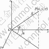
Fig.1 Imaging principle of 3D laser scanning
Axis x is in the cross direction scanning plane, axis y is also in the cross direction scanning plane and perpendicular to axis x, axis z is perpendicular to the cross direction plane. Observation value S of range finding is obtained through data collection, cross direction scanning angle α and longitudinal scanning angle θ of every laser impulse synchronously are measured by accurate clock controlling coder, thereby, the calculation equation of 3D laser footpoint coordinate is[14]:
 (2)
(2)
3 Cavity auto scanning laser system
Cavity auto scanning laser system scans the cavity by using “time-of-flight” laser measurement technique. The detector of this system is just 50 mm in diameter, the unit is designed to deploy down boreholes 300 m long, to be deployed uphill and horizontally 100 m long, covering the entire void up to a range of 150 m with the accuracy of ±5 cm. The scanned data can be used to establish 3D model through processing, and can be embedded into popular software such as SURPAC, VULCAN, AutoCAD and DATAMINE.
3.1 System’s composition and application
Cavity auto scanning laser system is composed of hardware and software. Hardware mainly includes the scanner, nose cone infra-red camera, bore track rods, cable and surface unit. Nose cone borehole infra-red camera in the probe is used to survey the borehole conditions; bore track rods are designed to accurately locate the cavity model and to avoid probe rotation in the borehole that will affect the data reading. Software mainly includes the controlling software and the laser point cloud edit software.
Due to various laser detector deploying methods, the cavity auto scanning laser system can fit for different types of cavity detection, including stope surveys, abandoned mine workings, orepass surveys, pillar recovery areas, backfilling areas, silo or ore bin surveys, tunnel profiling, survey of any inaccessible location and structural monitoring.
3.2 System detection procedure and data processing
The detection procedure (Fig.2) of cavity auto scanning laser system includes the following three steps:
1) deploying the scanner to cavity;
2) carrying out scan through controlling software;
3) processing the measured data using laser point cloud edit software to get 3D cavity model.
4 Application of cavity auto-scanning laser system in Luanchuan mine
4.1 Present situation and problems of Luanchuan mine
Sandaozhuang mine of Luoyang Luanchuan Molybdenum Group Inc. is now on the process of mining with 5.29×10⁸ t of molybdenum and tungsten geological
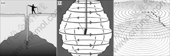
Fig.2 Detection procedure of cavity auto scanning laser system: (a) Deploying scanner to cavity; (b) Carring out scan; (c) Processing data
reserves, the average geological grade of molybdenum and tungsten of 0.11%, metal reserves of 6.725×10⁵ t, the verified molybdenum reserve is 2.52% of the world’s total. Sandaozhuang is an open pit with 30 kt/d production ability and 2×10⁸ annual production value. The mine experienced unreasonable underground mining for more than 20 years because of historical reasons, there are massive cavities left by sublevel open stope mining and large amount of unclear cavities left by private mining. Statistically, more than 100 cavities of various shape and size with total volume about 1×10⁷ m3 under the open pit, making the ore body in disastrous state. Meanwhile, these cavities suffered the ground pressure, weathering and blasting vibration, the rocks around them are in distortion and breakage, and their location, size and shape have already altered. As Sandaozhuang open pit bottom draws nearer to the underground cavity group, segregating layer between open pit bottom and cavities is thinner, both workers and large equipment in open pit are directly threatened by underground cavities. It is possible to occur fatal accidents at any time caused by surface collapse. The major task of the mine is to deal with those cavities under open pit. First of all, it is vital to accurately detect the shape, location and size of the cavities firstly to dispose them.
4.2 Detection method and its effect
Because of the problems described above, the cooperative research was carried out by researchers of Luoyang Luanchuan Molybdenum Group Inc. and School of Resources and Safety Engineering of Central South University. The cavity auto scanning laser system of MDL in UK was finally chosen to detect the cavities under open pit after analyzing the formative course of cavity. Therefore, the detection of some cavities under open pit bottom of Sandaozhuang mine was carried out in August of 2006 by personnel of MDL accompanied by researchers of School of Resources and Safety Engineering. This is the first application of cavity auto scanning laser system in China.
Four different boreholes were chosen to achieve the detection in order to verify the validity of cavity auto scanning laser system. Boreholes 1, 2 and 3 were in the open pit bottom, borehole 4 was on the surface outside the open pit boundary. Borehole 1 was drilled down to a cavity with 60 m in depth; borehole 2 was drilled down to a crack with 20 m in depth; borehole 3 was just a hole with depth of 8 m; borehole 4 was drilled down to underground cavity with 40 m in depth. Boreholes 2 and 3 were correctly detected by nose cone infra-red camera of the cavity auto scanning laser system in the process of detection. The model of cavity under borehole 1 in SURPAC is shown in Fig.3. The cavity is a normal and typical one left by conventional mining with about the same size in width and length, and about 10 m in height, the farthest distance in horizontal direction is 61 m. The model of cavity under borehole 4 in point cloud edit software of cavity auto scanning laser system is shown in Fig.4. The cavity is a anomalous one left by disorder mining, the farthest distance is about 8 m in vertical direction and 42 m in horizontal direction. The concave-convex status of this cavity can be clearly seen from Fig 4. The cavity auto scanning laser system is fully
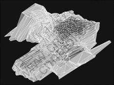
Fig.3 Model of cavity under borehole 1 in SURPAC
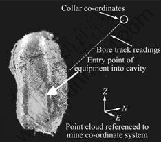
Fig.4 Model of cavity under borehole 4 in laser point cloud processing software
verified to be very suitable for underground cavities of Luanchuan Molybdenum Mine through the results above.
5 Conclusions
1) 3D laser detection method can provide accurate 3D cavity model to visually guide the disposal of underground cavities and voids. The model can also be built up by software SURPAC and DATAMINE, and incorporating with the mine reference frame to complete the whole mine 3D digital modeling. The application of cavity auto scanning laser system proves that it is an effective way for cavity detection.
2) The cavity auto scanning laser system can carry out cavity detection through borehole. This system can not only ensure the accurate detection, but also ensure the safety of detecting personnel, its unique character is very suitable for 3D detection of inaccessible underground cavities and voids such as the cavities under open pit of Sandaozhuang Molybdenum Mine.
3) Differing from those conventional cavity detection methods, 3D laser detection needs to know the rough location of the cavity in advance and then choose the drilling position. However, most of the cavities and voids’ situation are unclear, especially those inaccessible ones. Therefore, 3D laser detection method should be combined with the conventional detection methods to detect those unknown cavities. Location of the cavity can be determined by conventional detection methods in advance, and then the drilling position can be chosen to carry out detection by cavity auto scanning laser system.
4) Because laser reflection by water and glass is almost zero, and detection effect is limited by the visibility of underground cavity. The influences of water, fog (such as blasting fume) and humidity in the cavity to laser detection need to be further researched. At the same time, although laser equipment has been used in coal mine underground space, as the cavity auto scanning laser system is not specifically rated intrinsically safe, the detection feasibility of cavity auto scanning laser system in any area where there is risk of flammable gas (such as gas in coal mine) needs to be validated.
References
[1] LI Xi-bing, LI Di-yuan, ZHAO Guo-yan, ZHOU Zi-long, GONG Feng-qiang. Detecting, disposal and safety evaluation of the underground goaf in metal mines[J]. Journal of Mining and Safety Engineering, 2006, 23(1): 24-29. (in Chinese)
[2] YAN Chang-bin, XU Guo-yuan, ZHONG Guo-sheng. Research of composite prospecting and its application in complicated underground mined-out areas[J]. Journal of Liaoning Technical University, 2005, 24(4): 481-484. (in Chinese)
[3] MILLER F, POTVIN Y, JACOB D. Laser measurement of open stope dilution[J]. Canadian Institute of Mining Bulletin, 1992, 85(962): 96-102.
[4] HUBER D, VANDAPEL N. Automatic three-dimensional under- ground mine mapping[J]. International Journal of Robotics Research, 2006, 25(1): 7-17.
[5] FARDIN N, FENG Q, STEPHANSSON O. Application of a new in situ 3D laser scanner to study the scale effect on the rock joint surface roughness[J]. International Journal of Rock Mechanics and Mining Sciences, 2003, 41(2): 329-335.
[6] SYDDELL M. Company maps way forward for mining (laser scanning and digital imaging system)[J]. Australian Mining, 2005, 97(4): 30.
[7] GILBERTSON R J. The application of the cavity monitoring system at olympic dam operations [C]// Proceedings of Underground Operators Conference. Kalgoorlie: 1995, 245-252.
[8] JAROSZ A, SHEPHERD L. Application of cavity monitoring system for the control of dilution and ore loss in open stopes[C]// 11th International Congress of ISM. Cracow: 2000, 155-164.
[9] LUPTON J D. Cavity monitoring system and stope analysis [C]// Proceedings of Mass Mine Chile 2004. Santiago, 2004, 56-62.
[10] STUTTLE M C. Combined probe drilling and laser surveying for complex underground mapping[J]. Canadian Mining Journal, 1998, 119(6): 21-23.
[11] STUTTLE M C. Laser scanning aids underground mine mapping[J]. Mining Engineering, 1999, 51(3): 45-46.
[12] LI Xiang-yin, YAO Min-yu, LI Zhuo, CUI Ji. Laser principle technic and application[M]. Harbin: Harbin Institute of Technology Press, 2004. (in Chinese)
[13] ZHANG Yuan-zhi, HU Guang-yang, LIU Yu-tong, WANG Qing-zhou. Application of 3D laser scanning system in engineering projection[J]. Highway Transportation, 2001(9): 38-40. (in Chinese)
[14] GAO Shan. Application of the I-SITE 3D laser imagery system in mine survey[J]. Railway Investigation and Surveying, 2004, 30(6): 38-40. (in Chinese)
(Edited by YANG Hua)
Foundation item: Project(50490274) supported by the National Natural Science Foundation of China
Received date: 2007-10-21; Accepted date: 2007-12-12
Corresponding author: LIU Xi-ling, Doctor candidate; Tel: +86-731-8879612; E-mail: lxlenglish@163.com

