��Ħ�������·ǶԳ����ƶ�AA1050���Ͻ��ٽᾧ֯�������Ը������Ե�Ӱ��
��Դ�ڿ����й���ɫ����ѧ��(Ӣ�İ�)2019���11��
�������ߣ�Bianca. Delazari ZANCHETTA Vanessa. Karoline DA. SILVA Vitor. Luis. SORDI Jose Benaque RUBERT Andrea Madeira KLIAUGA
����ҳ�룺2262 - 2272
�ؼ��ʣ��ǶԳ����ƣ����Ͻ�X�������䣻����Ԫ������Ӧ��/Ӧ�����������
Key words��asymmetric rolling; aluminium alloy; X-ray diffraction; finite element analysis; stress/strain measurements; plasticity
ժ Ҫ���ڷǶԳ������У�����������Բ���ٶȲ�ͬ�����¸��ӵı�����ʽ���������С�ѹ������ת�������ȡ���Ҫ�����ṹ�ı��Ǿ���֯���ı仯�������Ͻ���˵�����������ٽᾧ��ı������������Ľ����̱���(ÿ���κ�ȼ�����(TRP) �����ʱ�)���˻���֯����չ����������ϵ����������Ԫģ���Ӧ�������Ӱ����ж���������������֯�������Ը������Ե�ʵ�����ݡ�����������ģ�ѹ�������ƺ�����������ת���Ӷ�����{111}//ND (����)֯����֡���������棬�ٶ��ݶȵľֲ��仯�����Ʒ������ת�������Ӷ�ʹ��ת����֯�����ӡ��˻������ĵ���Ҫ֯����ֵõ���������֯��ǿ�Ƚ��͡�ƽ���������(��r)���ͣ�����Erichsen�����У������е������¶��õ����Ƶĺ������Ժ�������ܡ������ʱ�Ϊ1.5��TRPΪ10%ʱ����r�ļ�������ѡ�
Abstract: In asymmetric rolling (ASR) the circumferential velocities of the working rolls are different. This yields a complex deformation mode with shear, compression and rigid body rotation components. The main microstructural modification is on crystallographic texture, and, for aluminium alloys, this may improve the deformability after recrystallization. This work correlated the process variables, thickness reduction per pass (TRP) and velocity ratio between the upper and bottom rolls, with the texture development and the plastic properties after annealing. Finite element (FE) simulations were performed to quantify the influence of the strain components. Experimental data on texture, and plastic anisotropy were analyzed. In the sheet centre a crystallographic rotation of the compression components about the TD (transverse direction) axis was obtained, which yielded the development of {111}//ND (normal direction) texture components. On the surfaces the local variation of the velocity gradients caused an extra rotation component about ND. This yielded the increment of rotated cube components. After annealing the main texture components at the sheet centre were maintained and the texture intensity decreased. The planar anisotropy ��r) was reduced but the normal anisotropy and deep drawability obtained by the Erichsen test were similar for all conditions. The most favourable reduction of ��r was obtained at a velocity ratio of 1.5 and TRP of 10%.
Trans. Nonferrous Met. Soc. China 29(2019) 2262-2272
Bianca. Delazari ZANCHETTA1, Vanessa. Karoline DA. SILVA2, Vitor. Luis. SORDI2, Jose Benaque RUBERT3, Andrea Madeira KLIAUGA2
1. Graduation Program in Materials Science, Federal University of Sao Carlos, Rod. Joao Leme dos Santos km 110, 18052-780 Sorocaba, Brazil;
2. Department of Materials Engineering, Federal University of Sao Carlos, Rod. Washington Luis km 235, 13565-905 Sao Carlos, Brazil;
3. Department of Mechanical Engineering, Federal University of Sao Carlos, Rod. Washington Luis, km 235, 13565-905 Sao Carlos, Brazil
Received 22 February 2019; accepted 23 July 2019
Abstract: In asymmetric rolling (ASR) the circumferential velocities of the working rolls are different. This yields a complex deformation mode with shear, compression and rigid body rotation components. The main microstructural modification is on crystallographic texture, and, for aluminium alloys, this may improve the deformability after recrystallization. This work correlated the process variables, thickness reduction per pass (TRP) and velocity ratio between the upper and bottom rolls, with the texture development and the plastic properties after annealing. Finite element (FE) simulations were performed to quantify the influence of the strain components. Experimental data on texture, and plastic anisotropy were analyzed. In the sheet centre a crystallographic rotation of the compression components about the TD (transverse direction) axis was obtained, which yielded the development of {111}//ND (normal direction) texture components. On the surfaces the local variation of the velocity gradients caused an extra rotation component about ND. This yielded the increment of rotated cube components. After annealing the main texture components at the sheet centre were maintained and the texture intensity decreased. The planar anisotropy (��r) was reduced but the normal anisotropy and deep drawability obtained by the Erichsen test were similar for all conditions. The most favourable reduction of ��r was obtained at a velocity ratio of 1.5 and TRP of 10%.
Key words: asymmetric rolling; aluminium alloy; X-ray diffraction; finite element analysis; stress/strain measurements; plasticity
1 Introduction
One of the limitations for a wider commercial application of aluminum alloys in automobile sheet panels is their lower drawability in comparison to steels. Rolled and recrystallized aluminium sheets are characterized by lower normal anisotropy (rm, usually 0.8), which yields poor resistance to thinning (steels have rm>1), and higher planar anisotropy (��r, usually around 0.3, when the ideal value is 0), which induces earing [1]. The most likely rolling texture is composed of the ��-fibre (main orientations include Brass {011}<211>, S {123}<634> and Copper {112}<111>), which evolves to the cube {001}<100> plus Goss {011}<100> orientations after annealing [2]. A strong cube orientation is responsible for the poor drawability, but more balanced strength and elongation properties may be achieved by a random [3] or a {111}//ND (normal direction) texture [4]. This arrangement can be obtained if shear strain is imposed throughout the entire sheet thickness [5,6].
Asymmetric rolling (ASR), is a modification of the conventional rolling process (SR), in which the circumferential velocities of the working rolls are different. This technique has been extensively studied in the past decade because it has the advantage of reducing rolling torque and pressure and an improvement of the rolled plate shape at velocity ratios between the upper and bottom rolls up to 1.2 [7]. It also imposes through thickness shear plus compressive strains, and introduces rigid body rotation components. This changes the deformation texture from pure compression to shear and rotation, a condition which generates lower texture intensity and greater microstructural refinement [8,9]. Texture modification is more efficient when velocity ratios higher than 1.4 are applied [10]. Texture modification improves the drawability values in aluminium alloys, a behaviour which has been observed by many authors [3-10]. Moreover, the technique has also been investigated as a manner to increase the mechanical isotropy of hexagonal metals such as magnesium and titanium [11,12]. However, ASR texture is very sensitive to processing parameters and different results are reported. For instance, both the ideal shear texture [4,6] and the FCC plane strain compression texture rotated about the sheet transverse direction (TD) axis [13-15] were observed. The main process parameters that affect the crystallographic orientation are friction coefficient, velocity ratio, thickness reduction per pass (TRP) and gap geometry.
The effect of asymmetry is to reduce the ��-fibre and accentuate the shear components across the sheet thickness, but it was also observed that the effect of friction, although quite hard to quantify, may be more determinant [10]. When the friction coefficient is high, both SR and ASR induce significant shear strain close to the sheet surface and yield shear textures [5,10]. This behaviour may be controlled by changing the roughness of the roll surfaces and the type of lubricant used in the process. For example, UTSUNOMIYA et al [16] achieved asymmetry under different lubrication conditions between top and bottom rolls. Moreover, the available experimental data show that ASR does not create the ideal shear texture if the sufficiently high friction is absent. SHORE et al [6] calculated that a minimum friction coefficient of 0.3 is necessary to transmit shear strains to the sheet. For example, SIMOES et al [17] obtained no difference in texture after ASR at low friction conditions and a velocity ratio of 1.4; WRONSKS and BACROIX [13] obtained a 8�� rotation at a ratio of 1.5, while LEE et al [5] obtained a 15�� rotation for the same ratio.
At a constant friction coefficient, the rotation of texture increases with the velocity ratio [6,13]. For the velocity ratios below 1.15, WRONSKI et al [14] observed an increase of cube texture, and a decrease of the ��-fibre components and above 1.15 the shifted brass component was stronger. For warm ASR the {111} fibre appeared for higher velocity ratios; the average texture intensity was significantly lower than that after cold rolling and the Cube and rolling components were reduced.
At a velocity ratio of 2, SIDOR et al [18] achieved shear textures through the sheet. They observed that the intensity of the shear texture developed after a sequence of ASR processes depends on the shear direction and TRP. Varying the initial thickness and the initial condition(annealed or work hardened) also changed the depth of the shear region. Therefore, decreasing the TRP should yield higher equivalent strains and higher shear strain components.
MA et al [19] studied the effect of TRP at a velocity of 1.25 and observed that smaller reduction rates yielded higher equivalent strains and higher shear strain components in the sheet centre, which in its turn promoted an increment of shear bands and a higher microstructural refinement when higher reduction rates are employed. The observation of deformed finite element meshes showed that the distortion caused by additional shear deformation in the centre layer was smaller than that on the surface. SIDOR et al [18] also observed that low thickness reductions (<10%), applied in the ASR process, causes an inhomogeneous distribution of deformation with pronounced shear localization within sub-surface regions.
On the other hand, GAO et al [20] calculated that the increment TRP increases the rolling force and the depth of shear deformation. LEE and LEED [21] could not differentiate the resultant texture on the surface of ASR samples deformed with different TRPs, and observed that at TRP of 5% and 50% grain refinement was maximal, but less efficient for intermediate values. Moreover it is not clear how this parameter influences the rigid body rotation that actuates the sheet��s central volume.
From the review mentioned above, it is still unclear in which conditions either shear or rotation takes place, and which is the influence on further annealing. Hence, the objective of this work is to correlate TRP and velocity ratios at high friction coefficients with the texture development and the plastic properties after annealing. Finite element (FE) simulations were performed in order to quantify the influence of shear and rigid body rotation in the process, and experimental data on texture, annealing texture and plastic anisotropy were analyzed.
2 Experimental
The initial material, a 7 mm-sheet of AA1050 alloy obtained by the roll casting process, was annealed at 350 ��C for 1 h prior to SR and ASR. Its chemical composition is given in Table 1.
In SR, the specimens were cold rolled at room temperature in a FENN 051 rolling mill, using conventional lubrication and 10% reduction per pass up to final thickness reduction of 70% was applied.
Table 1 Chemical composition of AA1050 aluminium alloy used in this work (wt.%)

The ASR was performed on 5 HP rolling mill, with two different roll diameter ratios of 1.5 and 2, the upper roll being the largest. The total thickness reduction was 50% for alloy samples. The angular speed was 23 r/min. The roll surfaces were machined producing a grooved surface, in order to avoid slip during the process and thus imposing the maximal friction. No lubricant was used.
The FE simulation was carried out using the DEFORM software. Sheets were considered as being elasto-plastic and the rolls perfect rigid bodies, respectively. The constitutive equation used was the Hollomon��s equation with the constants provided by the software (��=179��0.22, MPa) and the elastic modulus of 71 GPa. The plane-stress model was applied, forcing symmetry in the central plane consisting of the RD��ND and an adhesive frictional condition with the friction coefficient (m) of 0.9 was assumed. The FE simulation was compared with the change in shape of marks engraved at the sheets lateral. From the simulations, discrete values along the sheet thickness for shear strain ��xz and compression strain ��zz were calculated.
The numerical simulations consider the physical data of the rolling mill and the model symmetry; the results are displacements, strain and stress fields. To obtain the rigid body rotation of each element of the grid, a program routine was written using the procedure suggested by CODA [22] and BONET et al [23]. The initial (Ao) and final (Ax) spatial positions after the rolling process are mapped and give the known gradient deformation tensor F:
F=AxAo-1 (1)
The polar decomposition theorem of F was used to obtain the orthogonal tensor Q which is free of stretch and distortion influence and whose components depict only the rigid rotations of one point on a continuum media, and the tensor F is given by
F=QU (2)
U2=C=FTF
where C is the right Cauchy-Green tensor and U is the right stretch tensor. With F and the inverse U tensors, the orthogonal tensor Q is obtained by
Q=FU-1 (3)
From Q the rotation about the TD was calculated considering the projection of the rotation on the symmetry plane located in the middle of the sheet and having the normal RD and ND directions as the reference axis.
The experimental samples and numerical simulations were identified by four characters: the first two related to the roll velocity ratio (10 for the SR and 15 or 20 for the ASR corresponding to velocity ratios of 1.5 and 2) whilst the third and fourth characters are related to the TRP (5% or 10%).
After rolling the samples were annealed at 350 ��C for 1 h and quenched in water.
The microstructure was revealed by conventional polishing techniques followed by anodizing (2.5% HBF solution, 20 V, 3-5 min); optical microscopy was performed under polarized light. To characterize the degree of heterogeneity present in the sample, the texture was measured both on the upper sub-surface and on the centre of the as-rolled samples. After annealing only the centre of the sheets was analyzed. The (111), (200) and (220) pole figures, together with background and defocusing curves for further correction, were measured by X-ray diffraction on a Philips X-Pert MPD diffractometer located at Brazilian Nanotechnology National Laboratory using Co K�� radiation.
The orientation distribution functions (ODFs), were calculated from the three incomplete pole figures by using the series expansion method according to BUNGE [24] with the MTEX [25], routine running on the MATHLAB software. The orthorhombic symmetry was used for the SR samples and the triclinic symmetry for the ASR samples.
From the ASR sheets with approximately 3 mm in thickness, tension miniature samples with gauge lengths of 7 mm and 3 mm in width and 50 mm-diameter disc samples were cut by spark erosion. The rough surfaces were removed by grinding and the surface was finished with 1200 mesh abrasive paper, reducing the final thickness to 2 mm.
Tension tests were performed in an INSTRON universal testing machine. The elongation and lateral contraction were followed by an optical extensometer. The tests were performed at room temperature under a nominal strain rate of 1��10-3 s-1. The plastic anisotropy was calculated from the contraction ratios between the width (��w) and the thickness (��t) directions (r=��w/��t) measured on samples cut at 0��, 45�� and 90�� relative to the extrusion direction in the plane of the sheet.
The conventional average parameters of the normal and planar anisotropy are expressed by the rm and the ��r values, respectively:
 (4)
(4)
 (5)
(5)
Finally, in order to evaluate the deep drawing capability of the ECAP-processed samples, Erichsen tests following ASTM E643 were performed on the disc-shaped samples.
3 Results
Figure 1 shows the results of the FE simulation. The FE grid is distorted towards the rolling direction (Fig. 1(a)), indicating the effect of the different roll diameters. The total equivalent strain (Fig. 1(b)) has similar distribution for all four ASR samples: a gradient with lower strains at the sheet centre, higher strains on the surfaces and a more accentuated deformation close to the smaller roll, where the stress due to the smaller contact area is higher (Fig. 1(b)). Compressive strains are similar to all ASR samples, but as expected TRP of 5% produces greater gradients between surface and sheet centre (Fig. 1(c)). Differences between shear strains due to the variation of diameter ratio and TRP are greater than those for compression strains. TRP of 10% was more effective in transmitting shear than TRP of 5%, and increasing R1/R2 from 1.5 to 2 increases the shear strain (Fig. 1(d)). However, when the relative contribution of shear and compression ��xz/��zz (Fig. 1(e)) was analyzed, it is clear that with exception of the 2010 sample the compression is twice as strong than the shear and thus is responsible for the major contribution in the deformation. The simulation in high friction conditions predicted a range of rigid body rotations varying from 20�� to 40�� (Fig. 1(f)) which is higher than the one calculated under a friction coefficient of 0.3 by UNIWERSAL et al [26,27]. It also presents a gradient with lower intensity at the sheet centre and higher rotational field close to the rolls. Opposite to the shear, the predicted rigid body rotation on the surfaces was higher for TRP of 5% than for TRP of 10%.

Fig. 1 Strain distribuition in ASR samples
Figure 2 shows the results of texture measurements on the surface and the center of the ASR sheets. Upper and bottom surfaces yielded similar componentes, therefore only the results from upper surface are presented. A comparison of the texture intensities is presented in the dicussion section. The {111} pole figures are ploted with the RDxND reference axis to describe the rotation of the compression components about TD. On the CR samples the surface and center present the compression components copper {112}<111> and strong brass  , on the surface some deviation from these components due to suface fricion is also present.

Fig. 2 ODFs for ��2=45�� of cold-rolled samples using SR (1010) and ASR with roll diameter ratios of 1.5 and 2, and TRP of 5% and 10%
The ASR samples show very different textures on the surface and center. On the surface, it presents shear texture due to the high fricion coefficient and fibres <100>//ND, <112>//ND, <111>//ND and <011>//ND, the rotation took place about ND rather than about TD. The cube and rotated cube components increased when TRP was reduced from 10% to 5%. In the sheet center, rotation of the compression components, shift of the Brass orientations in the �� direction and strengthening of <112>//ND orientations were observed.
After annealing (Fig. 3), the SR sample shows a transition to the cube texture, whereas the ASR maintains most of the deformed components, but with increased spread. The most intense components in samples 1505 and 2005 were rotated Goss  and rotated Cube {001} <110>, in sample 1510 the <111>//ND fibre was more intense, and sample 2010 presented mainly the rotated cube and other <001>//ND fibre orientations with weak intensities in the <111>//ND fibre.

Fig. 3 ODFs sections at ��2=45�� of annealed samples (Contour levels are described in the scale bars; A: Annealed sample)
Figure 4 shows the typical microstructures of the as-rolled and annealed samples and the measured values of grain size and hardness are achieved after the heat treatment. After ASR the microstructure consists of highly elongated grains partitioned by shear bands induced by the asymmetry. The equivalent strains for all variables are very similar, as can be seen in Fig. 1(b).

Fig. 4 Optical micrographs of ASR sample (a) and sample after annealing at 350 ��C for 1 h (b), and grain size (c), hardness (d) and drawing test (Erichsen) (e) achieved after annealing
After annealing, all samples showed grain sizes around 30 ��m and harness of HV 20 at the centre. The surface and bottom layers were removed by grinding to prepare the tensile samples, thus removing the heterogeneities caused by the strain gradient of the process. The drawing test, shown in Fig. 3(e), yielded very similar rupture depths for all samples, showing that there was no significant change in this property due to the similarity of grain sizes and hardness.
The plastic anisotropy measurements are summarized in Table 2 and Fig. 5. A normal anisotropy of 0.6 was obtained for both SR and ASR samples confirming the Erichsen test and showing that there was no effect of the ASR in this property. On the other hand, there was a greater improvement of planar anisotropy for the ASR and annealed samples with the exception of sample 2010A, which presented high rotated cube fiber after annealing.
Table 2 Measured values of planar |��r| and normal rm anisotropy after annealing


Fig. 5 Measured plastic anisotropy (r) as function of axis orientation of tensile test
4 Discussion
The high friction condition imposed in the experimental conditions created two different zones along the sheet thickness: a surface region affected by the frictional forces at the roll/sheet interface, in which a rotational field about ND was predominant; and a central one, in which a rotational field around TD was predominant.
In the centre the expected shear textures with the transformation of Copper {112}<111> and Goss {110}<001> into {111}//ND orientations were obtained.
In shear deformation, the simple shear condition is achieved when the two shear planes are very close to each other and a thin deformation zone is formed. This is the case of equal channel angular pressing (ECAP) with a die with sharp inner and outer corners, low friction and the application of back pressure. However, when analysing the velocity gradient tensors in the shear plane, BEYERLEIN and TOME [28] found that when a fitting angle is introduced and deformation is comprised in a fan-like gap, the outer part of the channel is subjected to rigid body rotation and the inner part to simple shear, thus producing a mixed deformation mode. In the case of ASR, the shear surfaces are several millimetres apart, and under high friction, both shear and rigid body rotation gradients develop across the sample thickness. The FE simulation showed that a higher TRP transmits shear to the sheet centre whereas a lower TRP increases the rigid body rotation. Both components generate crystallographic rotation about TD and in the centre of the sample. This rotation is present in the centre of the analyzed samples.
For a TD symmetry axis, JIN and LLOYD [29] calculated by full constrained Taylor model that a ��xy/��xx equal to 1.5 should promote the rotation of the Cu {112}<111> to a <111>//ND orientation. LEE et al [5] observed shear textures in both SR and ASR at ��xy/��xx greater than 0.8. WRONSKI et al [14] showed that a more effective rotation would occur at a shear to compression ratio of 1. The experimental results in this work showed that under high friction and rigid body gradients, this shift takes place at ��xy/��xx of 0.5, which theoretically should yield compression components. Therefore, the rotation is not due to shear alone but is also influenced by the rigid body rotation imposed in the process.
Another feature, which cannot be explained only by the assumption of the TD symmetry axis, is the texture that is developed on the sheet surface. An extra set of simulations were performed without the restriction of a central RD��ND symmetry plane and for these the relative rotation close to the faster roll is represented in Fig. 6. Without the symmetry restriction, rotations about ND are present in the displacement field due to local variations in the stress field. No rotation is predicted for the SR, while for the ASR the rotation about ND increases when TRP is decreased from 10% to 5% and, the rotation about TD increases with the increase of the velocity ratio. At the lower TRP the differences between top and bottom roll are more accentuated. The net result in the ��2 sections of the ODFs is a spread of the orientations in the ��1 direction forming {100}//ND, {112}//ND and {111}//ND, as shown in Fig. 2. Figure 6 shows the intensity on the {100}//ND and {111}//ND fibres. The texture due to friction produces higher intensities for the cube-fibre (Figs. 6(b) and (c)) than for the ��-fibre (Figs. 6(d) and (e)) and the cube-rotated cube components increase at lower TRP.

Fig. 6 Calculated rigid body rotation close to faster roll interface when no symmetry is imposed in process (a), measured intensities of <001>//ND fibre at top (b) and bottom (c) surfaces, and <111>//ND fibre at top (d) and bottom (e) surfaces
The combination of rotated cube and �� fibre components at both upper and bottom surfaces is commonly observed in high friction conditions [10,21,30]. In a previous work on ECAP [31], when a rotation about ND is applied to a plane compression texture, the texture rotates towards the Goss and rotated cube orientations. This was characterized by shifts in the ��1 axis in the ODFs, whereas when the rotation axis is parallel to TD the texture shift occurred in ��, leading to the formation of <111> orientations by the displacement of Goss or Copper textures. This comparison reinforces the assumption that a stronger rotational field around ND exists due to the roll-sample interface under high friction; this has also been previously reported by JIN and LLOYD [10,29] in ASR experiments. The observed texture on the surface is the result of this complex strain generated by the high friction at the roll-sample interface.
SR has a very conservative strain path, which yields a strong crystallographic orientation and a more uneven strain distribution within the microstructure. The presence of pre-nucleated fine grains of cube orientation and their preferential growth over deformed S oriented grains generates the typical annealing texture with strong cube components [32]. On the other hand, ASR enforces a less conservative deformation path due to the strong rotation field caused by either shear or rigid body rotation. As a consequence, the deformed sample exhibits low texture intensities, as shown in Fig. 7.
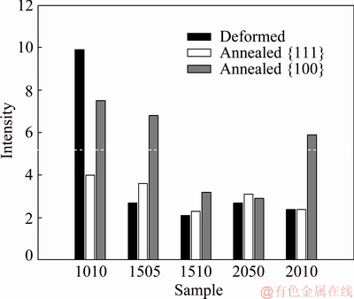
Fig. 7 Texture intensities in {111} and {100} pole figures of as-deformed sheet center
This should lead to a less oriented nucleation and growth process and, in fact, the randomization or the decrease of texture components after annealing, as shown in Fig. 7, has also been observed [29,33-36]. The stability of the �� fibre after heat treatment, as in the annealed samples 1510 A and 2005 A, however, has not been frequently observed, and in the context of plastic behaviour this favours planar anisotropy since the {111}//ND orientations generate the more isotropic behaviour observed in sample 1510A.
The plastic anisotropy of a random texture should increase rm and decrease ��r. CHEON et al [33] and KIM et al [34] obtained this shift towards more favourable anisotropy values in their experimental results, but this is not consensual in other literature data. A compilation of experimental rm and ��r values from Refs. [13,30,33-39], is shown in Fig. 8. The dispersion of data is wide since there is a strong variation of the resultant textures. Improvement of the normal anisotropy is less evident than that on the planar anisotropy, but the mean values indicate that the velocity ratio of 1.5 is the condition, confirmed by this work, in which a tendency to reduce the planar and increase the normal anisotropy is achieved in most cases.

Fig. 8 Lankford parameters of planar (��r) and normal (rm) anisotropy
5 Conclusions
(1) This work analysed the influence of the variation of velocity ratio and TRP in the ASR process under high friction coefficient on the post-annealing texture and its plastic anisotropy.
(2) The deformation presented a mixed mode with shear, compression and rigid body rotation components. In the sheet centre a crystallographic rotation of the compression components about the TD was obtained, that yielded the development of {111}//ND texture components. On the other hand, on the surface the local variation of the velocity gradients caused an extra rotation component about ND. This yielded rotated cube components.
(3) The increase of the velocity ratio accentuates the rotation about TD and the decrease in TRP accentuates the rotation about ND.
(4) Because the imposed deformation path in non-conservative after annealing most of the ASR texture components were maintained and the final texture had lower intensity.
(5) All conditions obtained similar deep drawability in the Erichsen test and plastic normal anisotropy, but at a velocity ratio of 1.5 and TRP of 10% the planar anisotropy was reduced.
Acknowledgment
This work was supported by Sao Paulo State Research Foundation (FAPESP 2016/10997-0) and by CAPES�C Brazil.
References
[1] Jahazi M, Goudarzi M. The influence of the mechanical parameters on the earing behaviour of 1050 and 1100 aluminium alloys [J]. Materials Processing Technology, 1997, 63: 610-613.
[2] Wang W, Helbert A L, Baudin T, Brisset F, Penelle R. Reinforcement of the Cube texture during recrystallization of A1050 aluminum alloy partially recrystallized and 10% cold-rolled [J]. Materials Characterization, 2012, 64: 1-7.
[3] Cho J H, KimHW Lim C Y, Kang S B. Microstructure and mechanical properties of Al-Si-Mg alloys fabricated by twin roll casting and subsequent symmetric and asymmetric rolling [J]. Metals and Materials International, 2014, 20: 647-652.
[4] Sidor J, Miroux A, Petrov R, Kestens L. Microstructural and crystallographic aspects of conventional and asymmetric rolling processes [J]. Acta Materialia, 2008, 56: 2495-2507.
[5] Lee K M, Kang H G, Huh M Y, Engler O. Effect of strain paths on development of shear textures during rolling in aluminum sheets [J]. Metals and Materials International 2010, 16: 851-856.
[6] Shore D, Kestens L A I, Sidor J, Houtte P, BaRlAt . Process parameter influence on texture heterogeneity in asymmetric rolling of aluminium sheet alloys [J]. International Journal of Materials Forming, 2018, 11: 297-309.
[7] Ji Y H, Park J J. Development of severe plastic deformation by various asymmetric rolling processes [J]. Materials Science and Engineering A, 2009, 499: 14-17
[8] Kim W J, Lee K E, Choi S H. Mechanical properties and microstructure of ultra fine-grained copper prepared by a high-speed- ratio differential speed rolling [J].Materials Science and Engineering A, 2009, 506: 71-79.
[9] ZUO Fang-qing, JIANG Jian-hua, SHAN Ai-dang, FANG Jian-min, ZHANG Xing-yao, Shear deformation and grain refinement in pure Al by asymmetric rolling [J]. Transactions of Nonferrous Metals Society of China, 2008, 18: 774-777.
[10] JinH, Lloyd D J. The different effects of asymmetric rolling and surface friction on formation of shear texture in aluminium alloy AA5754 [J]. Material Science and Technology, 2010, 26: 754-760.
[11] Zhao Y Q, Chen H M, Zhang J, Ma R, Liu Y, D,Wang Y N, Wang L, Zhang Q, Li W G. Influences of asymmetric reduction rolling on the microstructure and mechanical properties of AZ91 [J]. Acta Metallurgica Sinica English Letters, 2018, 31: 73-680.
[12] Chao Q, Cizek P, Wang J, Hodgson P D, Hossein B. Enhanced mechanical response of an ultrafine grained Ti-6Al-4V alloy produced through warm symmetric and asymmetric rolling [J]. Materials Science and Engineering A, 2016, 650: 404-413.
[13] WronskS i, Bacroix B. Microstructure evolution and grain refinement in asymmetrically rolled aluminium [J]. Acta Materialia 2014, 76: 404-412.
[14] Wronski S, Ghilianu B, Chauveau T, Bacroix B. Analysis of textures heterogeneity in cold and warm asymmetrically rolled aluminium [J]. Materials Characterization, 2011, 62: 22-34.
[15] CHEN Yang, TIAN Ni, ZHAO Gang, LIU Chun-ming, ZUO Liang. Evolution of (001)<110> orientation and related lattice rotation of A1 alloy 6111 during rolling [J]. Transactions of Nonferrous Metals Society of China, 2007, 17: 523-530.
[16] Utsunomiya H, Ueno T, Sakai T. Improvement in the r-value of aluminum sheets by differential-friction rolling [J]. Scripta Materialia, 2007, 57: 1109-1112,
[17] Simoes F J P, Alves de SousaR J, Gracio J J A, Barlat F, YoonJ W. Mechanical behavior of an asymmetrically rolled and annealed 1050-O sheet [J]. International Journal of Mechanical Sciences, 2008, 50: 1372-1380.
[18] Sidor J, Roumen J, Petrov H, Kestens L A I. Texture- induced anisotropy in asymmetrically rolled aluminium alloys [J]. Advanced Engineering Materials, 2011, 13: 494-954.
[19] Ma C, Hou L, Zhang J, Zhuang L. Influence of thickness reduction per pass on strain, microstructures and mechanical properties of 7050 Al alloy sheet processed by asymmetric rolling [J]. Materials Science and Engineering A, 2016; 650: 454-468.
[20] Gao H, Ramalingam S C, Barber G C, Chen G. Analysis of asymmetrical cold rolling with varying coefficients of friction [J]. Journal of Materials Processing Technology, 2002, 124: 178-182.
[21] Lee J K, LeeD N. Texture control and grain refinement of AA1050 Al alloy sheets by asymmetric rolling [J]. International Journal of Mechanical Sciences, 2008, 50: 869-887.
[22] Coda H B. An exact FEM geometric non-linear analysis of frames based on position description [J]. Proceedings of International Congress of Mechanical Engineering-ABCM, 2003, Sao Paulo.
[23] Bonet J, Wood R D, Mahaney J, Heywood P. Finite element analysis of air supported membrane structures [J]. Computer Methods in Applied Mechanics and Engineering, 2000, 190: 579-595.
[24] Bunge H J. Texture analysis in materials science [J]. Butterworts, London, 1982.
[25] Hielscher R, Schaeben H. A novel pole figure inversion method: specification of the MTEX algorithm[J]. Journal of Applied Crystallography, 2008, 41: 1024-1037.
[26] Uniwersal A, Wronski M, Wrobel M, Wierzbanowski K, Baczmanski A. Texture effects due to asymmetric rolling of polycrystalline copper [J]. Acta Materialia, 2017, 139: 30-38.
[27] Wronski M, Wierzbamowski K, Wronski S, Bacroix B, Lipinki P. Experimental and finite element analysis of asymmetric rolling of 6061 aluminium alloy using two-scale elasto-plastic constitutive relation [J]. Archives of Metallurgy and Materials, 2017, 62: 1991-1999.
[28] Beyerlein I J, Tome C N. Analytical modelling of material flow in equal channel angular extrusion (ECAE) [J]. Materials Science and Engineering A, 2004, 380: 171-190.
[29] Jin H, Lloyd D J. Evolution of texture in AA6111 aluminium alloy after asymmetric rolling with various velocity rations between top and bottom rolls [J]. Materials Science and Engineering A, 2007, 465: 267-273.
[30] Nam S K, Jeong H B, Kim I. Texture analysis of asymmetrically rolled and annealed AA 5083 Al alloy sheet [J]. Materials Research Innovations, 2011, 15: s454-s457.
[31] Kliauga A M, Bolmaro R E, Ferrante M. The evolution of texture in a equal channel pressed aluminum AA1050 [J]. Materials Science and Engineering A, 2015, 623: 22-31.
[32] Alvi M H, Cheong S W, Suni J P, Weiland H, Rollet A D. Cube texture in hot rolled aluminium alloy 1050 (AA1050)�C nucleation and growth behaviour [J]. Acta Materialia, 2008, 56: 3098-3108.
[33] Cheon B H, .Kim H W, Lee J C. Asymmetric rolling of strip Al-5.5Mg-0.3Cu alloy sheet: Effects on the formability and mechanical properties [J]. Materials Science and Engineering A, 2011, 528: 5223-5227.
[34] Kim H K, Kim H W, Cho J H, Lee J C. High-formability Al alloy sheet produced by asymmetric rolling of strip-cast sheet [J]. Materials Science and Engineering A, 2013, 574: 31-36.
[35] Sidor J, Miroux A, PetrovR, Kestens L. Controlling the plastic anisotropy in asymmetrically rolled aluminium sheets [J]. Philosophical Magazine, 2008, 30-32: 3779-3792.
[36] Kim G H, Nam S K, Lee D N, Kim I. A process for increasing plastic strain ratio of AA1050 Al alloy sheet [J]. International. Journal of Materials and Product Technology, 2017, 54: 202-211.
[37] Tamimi S, Correia J P, Lopes A B, SAhzi, Barlat F, Gracio J. Asymmetric rolling of thin AA-5182 sheets: Modelling and experiments [J]. Materials Science and Engineering A, 2014, 603: 150-159.
[38] Kang S B, Min B K, Kim H W, Wilkinson D S, Kang J, Effect of asymmetric rolling on the texture and mechanical properties of AA6111-aluminum sheet [J]. Metallurgical and Materials Transactions A, 2005, 36: 3141-63149.
[39] Kim I, Akramov S, JeongH B. Texture and formability development of asymmetric rolled AA 3003 Al alloy sheet [J]. International Journal of Modern Physics B, 2008, 22: 5895-65900.
Bianca. Delazari ZANCHETTA1, Vanessa. Karoline DA. SILVA2, Vitor. Luis. SORDI2, Jose Benaque RUBERT3, Andrea Madeira KLIAUGA2
1. Graduation Program in Materials Science, Federal University of Sao Carlos, Rod. Joao Leme dos Santos km 110, 18052-780 Sorocaba, Brazil;
2. Department of Materials Engineering, Federal University of Sao Carlos, Rod. Washington Luis km 235, 13565-905 Sao Carlos, Brazil;
3. Department of Mechanical Engineering, Federal University of Sao Carlos, Rod. Washington Luis, km 235, 13565-905 Sao Carlos, Brazil
ժ Ҫ���ڷǶԳ������У�����������Բ���ٶȲ�ͬ�����¸��ӵı�����ʽ���������С�ѹ������ת�������ȡ���Ҫ�����ṹ�ı��Ǿ���֯���ı仯�������Ͻ���˵�����������ٽᾧ��ı������������Ľ����̱���(ÿ���κ�ȼ�����(TRP) �����ʱ�)���˻���֯����չ����������ϵ����������Ԫģ���Ӧ�������Ӱ����ж���������������֯�������Ը������Ե�ʵ�����ݡ�����������ģ�ѹ�������ƺ�����������ת���Ӷ�����{111}//ND (����)֯����֡���������棬�ٶ��ݶȵľֲ��仯�����Ʒ������ת�������Ӷ�ʹ��ת����֯�����ӡ��˻������ĵ���Ҫ֯����ֵõ���������֯��ǿ�Ƚ��͡�ƽ���������(��r)���ͣ�����Erichsen�����У������е������¶��õ����Ƶĺ������Ժ�������ܡ������ʱ�Ϊ1.5��TRPΪ10%ʱ����r�ļ�������ѡ�
�ؼ��ʣ��ǶԳ����ƣ����Ͻ�X�������䣻����Ԫ������Ӧ��/Ӧ�����������
(Edited by Xiang-qun LI)
Corresponding author: Andrea Madeira KLIAUGA; Tel: +55-16-3351-8571; E-mail: kliauga@ufscar.br
DOI: 10.1016/S1003-6326(19)65132-0

