J. Cent. South Univ. Technol. (2008) 15: 106-111
DOI: 10.1007/s11771-008-0021-z

Mechanical mechanism analysis of tension type anchor based on shear displacement method
XIAO Shu-jun(肖淑君), CHEN Chang-fu(陈昌富)
(Institute of Geotechnical Engineering, Hunan University, Changsha 410082, China)
Abstract: Based on the fact that the shear stress along anchorage segment is neither linearly nor uniformly distributed, the load transfer mechanism of the tension type anchor was studied and the mechanical characteristic of anchorage segment was analyzed. Shear stress-strain relationship of soil surrounding anchorage body was simplified into three-folding-lines model consisting of elastic phase, elasto-plastic phase and residual phase considering its softening characteristic. Meanwhile, shear displacement method that has been extensively used in the analysis of pile foundation was introduced. Based on elasto-plastic theory, the distributions of displacement, shear stress and axial force along the anchorage segment of tension type anchor were obtained, and the formula for calculating the elastic limit load was also developed accordingly. Finally, an example was given to discuss the variation of stress and displacement in the anchorage segment with the loads exerted on the anchor, and a program was worked out to calculate the anchor maximum bearing capacity. The influence of some parameters on the anchor bearing capacity was discussed, and effective anchorage length was obtained simultaneously. The results show that the shear stress first increases and then decreases and finally trends to the residual strength with increase of distance from bottom of the anchorage body, the displacement increases all the time with the increase of distance from bottom of the anchorage body, and the increase of velocity gradually becomes greater.
Key words: anchor; anchorage segment; tension type; elasto-plasticity; mechanical analysis; shear displacement method; residual strength
1 Introduction
Ground anchor is one of the most common reinforcing methods and plays an important role in civil engineering. It can make effective use of the soil potential and enhance its self-stability, so construction safety and structure stability can be assured. So far, there has been many studies about anchor reinforcement[1-5]. According to the modes of load transfer between anchor and grout body, anchor can be divided into three types, which are tension type, pressure type and shearing type[1]. Tension type anchor is more commonly used in engineering practice and its reinforcement mechanism is to transmit the supporting force from anchor to stable stratum through bonding resistance between anchor and grout body as well as the resistance between grout body and the soil[6]. There are three failure modes of the tension anchor[7], that is, 1) anchor is stretch breaking, which makes it lose its bearing capacity, 2) the bonding resistance between anchor and grout body is too small for the anchor to be pulled out, and 3) the bonding resistance between the anchorage body and soil is too small for the anchorage body to be pulled out. The former two failure modes hardly occur in engineering practice under normal design and construction method, so the main task of anchor design is to determine the side resistance distribution between anchorage body and surrounding soil to avoid the last failure mode. Side resistance distribution of anchorage segment is conventionally assumed to be uniform[8]. However, the results of investigation[9-11] have shown that the side resistance is not in uniform distribution but it has a peak in the front part, then decreases gradually and finally approximates to zero. Therefore, it is of great importance to correctly determine the side resistance distribution and load transfer characteristic of anchorage segment among the anchor design. Many investigations on these problems have been carried out and have achieved some valuable conclusions[12-16]. In this work, softening feature of the soil surrounding anchorage body was considered, shear displacement method, which is usually used in the analysis of piles[17-18], was also introduced, and based on elasto-plastic theory, load transfer mechanism and bearing characteristic of tension type anchor were theoretically studied.
2 Anchorage mechanism of tension type anchor
2.1 Analytical model for tension type anchor
When the tension anchor (shown in Fig.1) is subjected to load P, the tension force will be equilibrated by frictional resistance between anchorage segment andsurrounding soil, which will be called as shear stress.
The shear stress-strain relationship of surrounding soil is shown in Fig.2. Straight line OA denotes that the soil is in elastic phase (phase I), AB in softening phase (phase Ⅱ) and BC in residual phase (phase Ⅲ). t1 and g1 respectively denotes shear strength and strain at peak point A, t2 and g2 respectively denotes shear strength and strain at point B is the initial of the residual phase.
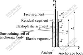
Fig.1 Schematic diagram of tension type anchor
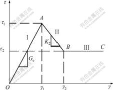
Fig.2 Relationship between shear stress and strain of soils
When the load P is small, the whole surrounding soil is in elastic phase (phase I shown in Fig.2); if P is large enough, the top part of surrounding soil of anchorage segment may come into softening phase (phase Ⅱ); if P keeps on increasing, the top part may come into residual phase (phase Ⅲ) and the middle part will come into softening phase. Here, the bottom part of surrounding soil with length of L1 (as shown in Fig.1) is elastic area (corresponding to elastic phase), the middle part with length of L2 is elasto-plastic area (corresponding to softening phase) and the top part with length of L3 is residual area (corresponding to residual phase). The total length of anchorage segment is Lb, Lb= L1+ L2+ L3.
As shown in Fig.2, shear stress-strain relationship can be expressed as
 (1)
(1)
where Ge is the elastic shear modulus and K2 is elasto-plastic shear modulus of anchorage inter face soil.
According to Ref.[19], considering elastic theory simultaneously, the expression of shear stress τ of soil surrounding pile and distance r from soil to pile center is τ=τ0r0/r, and the expression of shear strain γ is γ=ds/dr, where ro is anchorage body radius that equals the distance from anchorage body’s center to the interface between soil and anchorage body, τ0 is the shear stress of anchorage surface, s is the soil displacement surrounding anchorage body. The shear displacement method about pile was used in mechanical analysis of tension type anchorage body.
At the same depth z, according to Eqn.(1) and considering shear displacement method, the soil displacement at the anchorage body interface can be obtained as
 (2)
(2)
where rm is the soil radius surrounding anchorage body that shear displacement can be ignored.
In Eqn.(2), s is not only a function of radius r, but also depth z. The above discussions are all based on the same depth, while in the following of the paper the expression of shear displacement will be deduced at different depths. Displacement calculation in the phasesⅠand Ⅱ will be discussed at first. Let ξ= ln(rm/r0), then
in the elastic phase, there exists
 0≤z≤Lb (3)
in the elasto-plastic phase, there exists
 (4)
(4)
The second expression of Eqn.(4) is composed of two parts, elastic displacement se (Gp is plastic shear modulus of ancharge interface soil) and plastic displacement sp. According to Ref.[9], let 1/K2= -(1/Ge+1/Gp), we have
 (5)
(5)
 (6)
(6)
Assuming that the anchorage body material accords with Hooke law, and at depth z, the relationship between strain and axial force of the anchorage body will be
 (7)
(7)
where Ea is the modulus of the anchorage body.
Taking an anchorage element to analyze, the following expression can be obtained according to force equilibrium in the vertical direction
 (8)
(8)
Substituting Eqn.(7) into Eqn.(8) yields
 (9)
(9)
For tension anchor, the displacement of anchorage body sa should agree with the elastic displacement of soil se, that is to say, sa = se.
2.2 Elastic analysis
When the load is relatively small, there will only be elastic area in the anchorage body, and no elasto-plastic area. Here L2=0, substitute Eqn.(3) into Eqn.(9), and let λ1=Ea/Ge,  , then the differential equation can be obtained as follows:
 (10)
(10)
Considering boundary condition  and
and  , and combining with Eqn.(7), by solving Eqn.(10), shear stress is given as
 (11)
(11)
The soil shear stress τ can be obtained from Eqn.(3) as
 (12)
(12)
Substituting Eqn.(12) into Eqn.(8), the anchorage axial force is given as
 (13)
(13)
According boundary condition  , the elastic limit load is obtained as
 (14)
(14)
2.3 Elasto-plastic analysis
When the load is relatively large, the surrounding soil will enter into elasto-plastic phase. For tension anchor, the elasto-plastic area will appear at the top of anchor, that is the area of L1≤z≤Lb, and elastic area will appear at the bottom, that is the area of 0≤z≤L1. At the point z =L1, combining with Eqn.(12), the expression of L1 can be given as
 (15)
(15)
The displacement, shear stress and axial force of the elastic area (0≤z≤L1) can be calculated by the above method (as shown in section 2.2).
According to the first expression of Eqn.(4), the soil displacement at the point z=L1 is
 (16)
(16)
For the elasto-plastic area L1≤z≤Lb, the soil displacement can be calculated by Eqn.(5), but the equation is a transcendental equation and τ cannot be directly solved through the relationship between τ and s. Therefore, the following means are adopted.
In Eqn.(5), let  , the equation is given as
 (17)
(17)
Substituting Eqn.(17) into Eqn.(9) yields
 (18)
(18)
where  , according to Eqn.(17),
  .
.
By solving the differential Eqn.(18), and considering boundary condition and  , the soil displacement (L1≤z≤Lb) is given by
 (19)
(19)
Therefore,
 (20)
(20)
According to Eqns.(6) and (20), the plastic displacement of surrounding soil sp, which is the slip displacement between soil and anchorage body, can be expressed as
 (21)
(21)
The total displacement of anchor sb contains the elastic and plastic displacements of anchorage segment and elastic deformation of free segment. Therefore
 (22)
(22)
where rd is the anchor radius, Ed is the elastic modulus of anchor and Ld is the free segment length of anchor.
The axial force can be calculated by the following expression:
 (23)
(23)
Thus
 (24)
(24)
If the load P increases again, the top of anchorage body will enter into residual phase ( , L3≠0,
shown as Fig.1). According to Eqn.(20), let τ(z)=τ2, the length of L3 can be obtained. Here, P(z) cannot be calculated by Eqn.(24), it should be calculated by subsection integral according to Eqn.(23). With the increment of the load P, iteration and tentative calculation is carried out and the program is used to gain the maximum bearing capacity.
If the load P further increases, the area of the soil entering into residual phase will become larger and larger. When shear stress of anchorage interface can no longer resist the load P, according to Eqn.(23), the anchorage body will be collapsed.
3 Example and discussion
3.1 Conclusion analysis
Assume Lb=8 m, Ge=15 MPa, r0=130 mm, rd=15.2 mm, Ea=12 GPa, Ed=200 GPa, Ld=5 m, τ1=200 kPa, τ2=0.4τ1 and |K2|=0.3Ge. Under different loads P, the variations of shear stresses and displacements along anchorage segment are shown in Figs.3 and 4, respectively. Based on the above parameters, the elastic limit load that the whole interface of anchorage body keeps in elastic phase is obtained, Pe=694 kN. Fig.3 shows that when the whole anchorage segment is in elastic phase, the anchorage shear stress increases with the increment of the distance from bottom of anchorage body. With the increase of the load P, however, the top part of anchorage body will enter into elasto-plastic phase, and shear stress will decrease; when the shear stress reduces to τ2, the top part of anchorage will enter into residual area, and the shear stress will no longer change. Fig.3 also shows that shear stress peak point moves far from the top part of the anchorage body with the increase of the load P. According to Fig.4, from bottom to top part of anchorage segment, the displacement increases gradually; and as the top part of anchorage segment enters into elasto-plastic phase and residual phase, the displacement increases more rapidly, which can offer important theoretical support for evaluating pre-stressing loss of anchor and predicting displacement of anchor retaining structure.
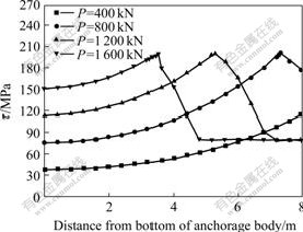
Fig.3 Shear stress distribution of anchorage segment at Lb=8 m
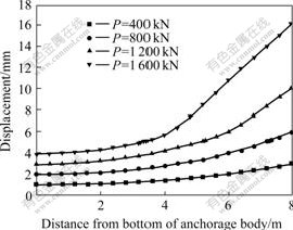
Fig.4 Displacement distribution of anchorage segment at Lb=8 m
3.2 Discussion
The maximum bearing capacity can be obtained by iteration and tentative calculation after surrounding soil enters into residual phase. The FORTRAN language is used in this work. It is known that P=1 300 kN is the turning point, and the anchor maximum limit load Pu= 1 300 kN. After P exceeds 1 300 kN, the anchor will collapse. The gained Pu can offer material instruction for engineering after considering safety factor. And in Fig.3, P=1 600 kN is only the theoretical condition, it will not appear in application. With different anchorage lengths Lb, the maximum bearing capacity Pu can also be obtained. The conclusion is that when Lb is less than 8 m, Pu is less than 1 300 kN; when attains or exceeds 8 m, Pu will retain to 1 300 kN. So the effective anchorage length is 8 m. The presented method cannot give theoretical expression of effective anchorage length, but it can obtain the value of effective anchorage length by calculation, which has practical significance in engineering.
The shear stress of anchorage interface plays an important role for the maximum bearing capacity Pu, so the influence on the shear stress is discussed when the parameters change. Here P=1 200 kN is used to calculate. Figs.5 and 6 show the shear stress variety following the varieties of the anchorage radius r0 and anchorage length Lb, respectively. Following the increment of r0, the elastic length of surrounding soil increases, and the anchorage bearing capacity is strengthened. From Fig.6, following the increment of Lb, the shear stress distribution changes, the shear stress peak point moves to the bottom of anchorage body, which shows that when Lb is relative large, the elastic length will be larger when the anchor collapses.

Fig.5 Shear stress distribution when r0 changes
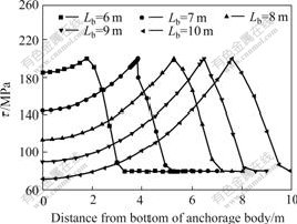
Fig.6 Shear stress distribution when Lb changes
4 Conclusions
1) The mechanical behavior analysis of tension anchor is carried out based on shear displacement method. Considering the condition that soil surrounding the anchorage body would soften and then enter into residual area, shear stress state of the soil can be divided into three phases during loading. The calculation formula of elastic limit load is obtained considering different stress states. When the load exceeds elastic limit load, some soil surrounding anchorage body will enter into elasto-plastic phase, and calculation formula of the elastic length is been deduced. Meanwhile, the displacement, shear stress and axial force of anchorage segment are discussed and the calculation formula is respectively developed according to different phases of soil surrounding anchorage body.
2) An example is given to illustrate the presented method. The elastic limit load and maximum bearing capacity of anchor, and the distribution of the shear stress and displacement of anchorage segment are investigated. The results show that the soil under relative large load will first partly enter into elasto-plastic phase and then partly enter into residual phase, whereas the shear stress will first increase and then decrease and finally trend to the residual strength with increase of distance from bottom of the anchorage body. The displacement in that period increases all the time with the increasing of distance from bottom of the anchorage body, and the increase velocity gradually becomes greater.
3) The anchorage bearing capacity increases with the increment of anchorage radius, but it does not increase all the time, which shows that effective length exists and its length is obtained. The maximum bearing capacity increases first and then holds in a certain value with the increment of the anchorage length. So for the given soil and anchorage body, when the anchorage length arrives to the effective anchorage length, increasing maximum bearing capacity should increase the anchorage radius or enhance soil shear strength or other measures, increasing anchorage length will have no effect.
References
[1] LU Shi-liang, TANG Lei, YANG Xin-an. Anchorage force and technology[M]. Beijing: Coal Industry Press, 1998. (in Chinese)
[2] LUTZ L, GERGELEY P. Mechanics of band and slip of deformed bars in concrete[J]. Journal of American Concrete Institute,1967, 64(11): 711-721.
[3] HANSOR N W. Influence of surface roughness of prestressing strand on band performance[J]. Journal of Prestressed Concrete Institute, 1969, 14(1): 32-45.
[4] GOTO Y. Cracks formed in concrete around deformed tension bars[J]. Journal of American Concrete Institute, 1971, 68(4): 244-251.
[5] LI Xi-bing, ZHOU Zi-long, LI Qi-yue, HU Liu-qing. Parameter analysis of anchor bolt support for large-span and jointed rock mass[J]. J Cent South Univ Technol, 2005, 12(4): 483-487.
[6] FANG Cong-yan, ZUO Jia-shou. Experimental study on anchorage mechanism of anchor bolt[J]. Journal of Hohai University: Natural Sciences, 2005, 33(6): 696-700. (in Chinese)
[7] LI Hai-guang. New type retaining structure design and engineering example[M]. Beijing: China Communication Press, 2003. (in Chinese)
[8] Ministor of Water Resources Hydroelectric Programming Design General Institute. Pre-stressing anchorage technology[M]. Beijing: China Water Power Press, 1999. (in Chinese)
[9] CHEN Miao-feng, TANG De-gao, ZHOU Zao-sheng. The test research of anchor reinforcement mechanism[J]. Building Technique Development, 2003, 30(4): 21-23. (in Chinese)
[10] WOODS R I,BARKHORDARI K. The influence of bond stress distribution on ground design[C]// Proc Int Symp on Ground Anchorages and Anchored Structures. London: Themas Telford, 1997: 300-306.
[11] HE Ruo-lan, ZHANG Ping, LI Ning. Working mechanism of fully grouted bolt in pull-out working state[J]. J Cent South Univ: Science and Technology, 2006, 37(2): 401-407. (in Chinese)
[12] KILIC A, YASAR E, ATIS C D. Effect of bar shape on the pull-out capacity of fully grouted rockbolts[J]. Tunnelling and Underground Space Technology, 2003, 18: 1-6.
[13] JIANG Zhong-xin. A Gauss curve model on shear stress along anchoring section of anchoring rope of extensional type force[J]. Chinese Journal of Geotechnical Engineering, 2001, 23(6): 696-699. (in Chinese)
[14] HE Si-ming, WANG Cheng-hua, WU Wen-hua. Analysis on loading-deformation of prestressed cable based on damage theory[J]. Chinese Journal of Rock Mechanics and Engineering, 2004, 23(5): 786-792. (in Chinese)
[15] LI C, STILLBORG B. Analytical models for rock bolts[J]. International Journal of Rock mechanics and Mining Science, 1999, 36: 1013-1029.
[16] CAI Y, ESAKI T, JIANG Y J. A rock bolt and rock mass interaction model[J]. International Journal of Rock Mechanics and Mining Sciences, 2004, 41: 1055-1067.
[17] ZHAO Ming-hua, ZHANG Ling, YANG Ming-hui. Settlement calculation for long-short composite piled raft foundation[J]. J Cent South Univ Technol, 2006, 13(6): 749-754.
[18] ANIL M, CHEN C H, RAJ O. Simplified analysis method for micropile pullout behavior[J]. Journal of Geotechnical and Geoenvironmental Engineering, 2004, 130(10): 1024-1033.
[19] ZAI Jin-min. Theory and application of composite pile foundation[M]. Beijing: China Water Power Press, 2004. (in Chinese)
(Edited by CHEN Wei-ping)
Foundation item: Project(20050532021) supported by the Research Fund for the Doctoral Program of Higher Education
Received date: 2007-07-11; Accepted date: 2007-08-29
Corresponding author: CHEN Chang-fu, Professor, PhD; Tel: +86-731-8821660; E-mail: cfchen@163.com

