Analytical solution for evaluating deformation response of existing metro tunnel due to excavation of adjacent foundation pit
来源期刊:中南大学学报(英文版)2021年第6期
论文作者:江杰 周晓军 邱居涛 张越峰 潘英东
文章页码:1888 - 1900
Key words:metro tunnel; simplified analytical method; additional stress; Timoshenko beam; Winkler foundation
Abstract: The excavation of foundation pit generates soil deformation around existing metro tunnel with shield driving method, which may lead to the deformation of tunnel lining. It is a challenge to evaluate the deformation of shield tunnel accurately and take measures to reduce the tunnel upward displacement as much as possible for geotechnical engineers. A new simplified analytical method is proposed to predict the longitudinal deformation of existing metro tunnel due to excavation unloading of adjacent foundation pit in this paper. Firstly, the additional stress of soils under vertical axisymmetric load in layered soil is obtained by using elastic multi-layer theory. Secondly, the metro tunnel is regarded as a Timoshenko beam supported by Winkler foundation so that the shear effect of tunnels can be taken into account. The additional stress acting on the tunnel due to excavation unloading in layered soil are compared with that in homogeneous soil. Additionally, the effectiveness of the analytical solution is verified via two actual cases. Moreover, parametric analysis is conducted to investigate the responses of the metro tunnel by considering such factors as the variation of subgrade coefficient, offset distance from the excavation center to tunnel longitudinal axis as well as equivalent shear stiffness. The proposed method can be used to provide theoretical basis for similar engineering project.
Cite this article as: QIU Ju-tao, JIANG Jie, ZHOU Xiao-jun, ZHANG Yue-feng, PAN Ying-dong. Analytical solution for evaluating deformation response of existing metro tunnel due to excavation of adjacent foundation pit [J]. Journal of Central South University, 2021, 28(6): 1888-1900. DOI: https://doi.org/10.1007/s11771-021-4737-3.

J. Cent. South Univ. (2021) 28: 1888-1900
DOI: https://doi.org/10.1007/s11771-021-4737-3

QIU Ju-tao(邱居涛)1, 2, JIANG Jie(江杰)3, ZHOU Xiao-jun(周晓军)1, 2,ZHANG Yue-feng(张越峰)1, 2, PAN Ying-dong(潘英东)1, 2
1. Key Laboratory of Transportation Tunnel Engineering, Ministry of Education, Southwest Jiaotong University, Chengdu 610031, China;
2. School of Civil Engineering, Southwest Jiaotong University, Chengdu 610031, China;
3. College of Civil Engineering and Architecture, Guangxi University, Nanning 530004, China
 Central South University Press and Springer-Verlag GmbH Germany, part of Springer Nature 2021
Abstract: The excavation of foundation pit generates soil deformation around existing metro tunnel with shield driving method, which may lead to the deformation of tunnel lining. It is a challenge to evaluate the deformation of shield tunnel accurately and take measures to reduce the tunnel upward displacement as much as possible for geotechnical engineers. A new simplified analytical method is proposed to predict the longitudinal deformation of existing metro tunnel due to excavation unloading of adjacent foundation pit in this paper. Firstly, the additional stress of soils under vertical axisymmetric load in layered soil is obtained by using elastic multi-layer theory. Secondly, the metro tunnel is regarded as a Timoshenko beam supported by Winkler foundation so that the shear effect of tunnels can be taken into account. The additional stress acting on the tunnel due to excavation unloading in layered soil are compared with that in homogeneous soil. Additionally, the effectiveness of the analytical solution is verified via two actual cases. Moreover, parametric analysis is conducted to investigate the responses of the metro tunnel by considering such factors as the variation of subgrade coefficient, offset distance from the excavation center to tunnel longitudinal axis as well as equivalent shear stiffness. The proposed method can be used to provide theoretical basis for similar engineering project.
Key words: metro tunnel; simplified analytical method; additional stress; Timoshenko beam; Winkler foundation
Cite this article as: QIU Ju-tao, JIANG Jie, ZHOU Xiao-jun, ZHANG Yue-feng, PAN Ying-dong. Analytical solution for evaluating deformation response of existing metro tunnel due to excavation of adjacent foundation pit [J]. Journal of Central South University, 2021, 28(6): 1888-1900. DOI: https://doi.org/10.1007/s11771-021-4737-3.
1 Introduction
The rapid development of modern cities in the world regularly brings a series of construction of high-rise buildings above existing tunnels in urban areas so as to meet the residents’ growing demand for housing. It is well known that excavation of foundation pit is prior to construction of buildings. The earth pressure will be redistributed inevitably and the soil deformation will be changed during soil excavation in adjacent foundation pit, which may cause great damage to metro tunnel such as deformation of lining segment, distortion of track, groundwater leakage, etc. So many geotechnical engineers investigated how to ensure the safety of metro tunnel during the excavation of foundation pit.
In the past decades, many works and tests have been conducted to investigate the impact of shield tunnel under excavation unloading in adjacent foundation pit [1, 2]. However, the results of the tests depend largely on factors such as the precision of the equipment, materials, working condition, etc. In particular, it costs much labor and time in performing the tests. Generally, there are two methods to conduct computation and analysis, and one is numerical simulation. Some researchers have investigated the mode of tunnel deformation under excavation unloading using 3D FEM [3-7], which takes constitutive relationship of soil into account and obtains visual result by software. But establishing finite element model is a tedious task and a time-consuming work, which is not suitable for geotechnical engineers working in real engineering project. The other is analytical solution, which can be easily used by geotechnical engineers as a quick and accurate approach to evaluate and address the potential risk of metro tunnel induced by adjacent excavation [8-10]. As a result, a two-stage method is accepted widely by academics in recent years [11-16]. Firstly, the additional stress of soil under excavation unloading is calculated based on analytical solution. Secondly, the deformation of shield tunnel caused by additional stress is calculated based on elastic homogeneous foundation model. However, it is generally assumed that the soil in construction site is homogeneous, and the layered soil is generally omitted for the sake of simplification and reduction. Thus, it is important to realize how the stress is distributed in layered soil while analyzing the influence of foundation pit excavation on adjacent existing metro tunnel. For analytical solution of soil-tunnel interaction, a common simplified approach in which the shield tunnel is considered as an elastic continuum beam is proposed. ZHANG et al [12] established a prediction model that treated shield tunnel as an Euler-Bernoulli beam lying on Winkler foundation. Other researchers considered the shear effect between foundation springs and even the impact of the lateral soil deformation on tunnel by using Winkler-Pasternak foundation [15, 17] and Kerr foundation [16]. Actually, shield tunnel usually consists of a series of lining segments connected with bolts. Lining segments may suffer from shear dislocation when subjected to external loads. Deformation of shield tunnel includes bending deformation and shear deformation. However, shear effect is not deliberately embodied in Euler-Bernoulli beam, therefore, the results derived from this model often overestimate the deformation of the metro tunnel and other reinforced concrete underground works.
A new analytical approach is established to investigate the longitudinal deformation of tunnel caused by excavation unloading by using Timoshenko theory based on Winkler foundation. Compared with Mindlin solution [18], the elastic multi-layer theory can be employed to consider the change of elastic modulus and Poisson ratio, which makes theoretical results more accurate. Moreover, Timoshenko theory is not only applied to reflect bending deformation but also indicate the shear deformation of the metro tunnel. The proposed analytical solution is verified with two cases at two different construction sites. According to the proposed analytical solution, the influence of the subgrade coefficient, the offset distance between the excavation center and the tunnel longitudinal axis as well as the equivalent shear stiffness on the tunnel response is discussed.
2 Elastic multi-layer theory
To analyze the longitudinal deformation of existing shield tunnel due to excavation of an adjacent foundation pit, Elastic multi-layer theory is employed. And a case is illustrated in Figure 1. Figure 1 shows the layered soil under axisymmetric vertical load p(r) within a circle with a radius of R,and R does not comprise the whole circle. It is obvious from Figure 1 that the number of layer in the system is n, where △hi corresponds to the thickness of the i-th soil layer, Ei and μi are elastic modulus and Poisson ratio of the i-th layer, respectively.
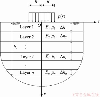
Figure 1 Multi-layered soil under uniform axisymmetric vertical load p(r) within circle with radius of R
Based on Burmister’s theory [19], the general solution of the multilayer soil is derived as follows:
 (1)
(1)
 (2)
(2)
 (3)
(3)
 (4)
(4)
where u and ω denote the displacement in r-direction and z-direction, respectively; τrz is the shear stress in plane rOz; σz is the axial stress in z-direction; ξ is the integral parametric variable; J0(ξr) and J1(ξr) indicate the Bessel function with order 0 and 1, respectively; is obtained from Hankel transformation and its formula is defined in Eq. (5):
 (5)
(5)
The vector functions L and K are expressed as follows:
 (6)
(6)
where hi is the distance from the bottom of the i-th layer to ground surface; z denotes the vertical distance from the place where vertical load is applied to the calculation point. Transfer matrix Φ(ξ, z) is defined below:
 (7)
(7)
Transfer matrix Φ(ξ, z) contains elastic modulus Ei and Poisson ratio μi of each layer. The expression of Φij is obtained from Ref. [20].
2.1 Analytical solution of stress on surface of layered soil under concentrated load
When concentrated load is applied on the surface of layered soil, the expression of p(r) is derived as:
 (8)
(8)
where δ(r) is Dirac function and it can be defined as:
 (9)
(9)
Combining with Eqs. (5), (8) and (9), we obtain the expression ofby using Hankel transformation:
 (10)
(10)
Substitution of Eq. (10) into Eq. (4) yields the general solution of vertical stress σz under concentrated load, it is expressed in Eq. (11):
 (11)
(11)
2.2 Analytical solution of stress on surface of layered soil under rectangular uniform load
As shown in Figure 2, the area of rectangular load that acts on the surface of layered soil is supposed to be a×b.
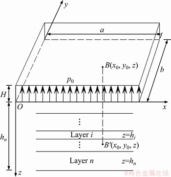
Figure 2 Rectangular load distribution of layered soil
The pressure p(r) is expressed as:
 (12)
(12)
p0 is obtained from:
 (13)
(13)
where γi and hi are the unit weight and the thickness of each layer above the bottom of excavation site, respectively.
The general solution of vertical stress is obtained under rectangular uniform load by integrating Eq. (11) over the rectangular area, which is the major premise for analyzing soil-tunnel interaction. It is indicated below:

 (14)
(14)
where Ω is the area of rectangular uniform load.
3 Soil-tunnel interaction
3.1 Analytical solution of longitudinal deformation of metro tunnel
The calculation model of soil-tunnel interaction is depicted in Figure 3. Furthermore, this calculation model is only restrained to the situation that the behavior of soil is in linear elastic state and the tunnel is exposed to surrounding soil completely.
Based on Ref. [14], the differential equation of Timoshenko beam lying on Winkler foundation is obtained as follows:
 (15)
(15)
 (16)
(16)
where σz is additional stress and is obtained from Eq. (14); k denotes subgrade coefficient; EI stands for the flexural stiffness; D is the outer diameter of the metro tunnel; ω indicates the vertical displacement of the metro tunnel; T =λGA is the shear stiffness of tunnel; λ is the shear coefficient and is set to be 1/2 for annular cross section; G and A are the shear modulus and the cross sectional area of the metro tunnel, respectively.
Equation (15) can then be transformed as follows:
 (17)
(17)
 (18)
(18)
Equation (18) is the analytical solution of the rotation angle. Substituting Eqs. (17) and Eq. (18) into Eq. (16), we obtain following expression:
 (19)
(19)
If the terms that contain shear stiffness are removed, then Eq. (19) is expressed as:
 (20)
(20)
Equation (20) indicates the differential equation of Euler-Bernoulli beam based on Winkler foundation.
The homogeneous equation of Eq. (19) is then represented as:
 (21)
(21)
Meanwhile, the characteristic equation of above expression is:
 (22)
(22)
The solutions of the characteristic equation are obtained as:
 (23)
(23)
Therefore, the general solution of Eq. (21) is deduced below:

 (24)
(24)
As x tends to infinity, the metro tunnel is not affected by excavation and ω is equal to zero. So the general solution is simplified as:
 (25)
(25)
The special solution ω′(x) of Eq. (19) is zero at x=0. When an individual point load acting on the beam where x=0, the boundary conditions are obtained according to the geometric symmetry, namely:
 (26)
(26)
Combining with Eq. (25) with Eq. (26), the formula of ω(x) is expressed as:
 (27)
(27)
As shown in Figure 4, assuming the additional load on arbitrary location η of the beam is σz(η)dη. The vertical displacement at any point x on the beam is then obtained through coordinate transformation:

 (28)
(28)
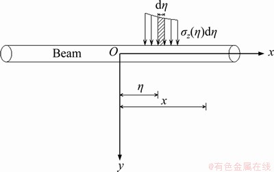
Figure 4 Model of beam subject to uniform load
Finally, the vertical displacement of tunnel induced by soil excavation in foundation pit is derived by integrating Eq. (28):


 (29)
(29)
where |x2-x1| indicates the length of the investigated tunnel.
On the basis of Timoshenko’s theory [21], the longitudinal bending moment of the metro tunnel is deduced as:
 (30)
(30)
3.2 Related parameters
While investigating the response of metro tunnel, Winkler foundation model contains only one parameter, namely the coefficient of subgrade k, which is used to consider the compression of the ground and is calculated according to the expression obtained by KLAR et al [22].
 (31)
(31)
where Es is the elastic modulus of soil in which metro tunnel is located.
The metro tunnel is fabricated with massive segments connected by bolts, which leads to the degradation in longitudinal shear stiffness when large deformation occurs between tunnel linings. Referring to the method presented by ZHANG et al [23], the expression of the equivalent shear stiffness (T)eq is derived as:
 (32)
(32)
where ζ is a modified factor considering the degradation in shear stiffness of the metro tunnel and assumed to be 0.05 in this paper.
4 Parametric analysis
In actual engineering practice, the static behavior of metro tunnel is dominated by such factors as tunnel’s outer diameter, properties of soil and the offset distance between the foundation pit and tunnel longitudinal axis, etc. Thus, several different influence factors are employed to investigate the impact of excavation on metro tunnel’s deformation in this section. The foundation pit has a length of 60 m and a width of 30 m. The excavation depth reaches 6 m. A metro tunnel directly exists underneath the foundation pit. The depth of the tunnel axis is of 15 m and the tunnel longitudinal axis is parallel to the short side of the foundation pit. In reference to the cross-sectional area and lining segment of metro tunnel in Shanghai, China, the tunnel geometry and the soil layer are the same as that in Case III.
4.1 Subgrade coefficient
The subgrade coefficient k is a vital parameter based on Winkler foundation in calculating the stress and deformation of metro tunnel. The results will be different if different values are set for subgrade coefficient. In this section, the subgrade coefficients are set to be 0.5k, 0.75k, 1.0k, 1.25k, 1.5k and 1.75k. Furthermore, the tunnel outer diameter is taken into consideration in order to investigate the mechanical behavior of tunnel due to excavation. Both Figures 5 and 6 illustrate the maximum displacement and maximum bending moment of the tunnel under different subgrade coefficients, respectively. As the tunnel outer diameter increases, both of them increase. Conversely, the tunnel displacement and bending moment decrease rapidly with a greater subgrade coefficient at each tunnel outer diameter. It is concluded that the higher the subgrade modulus is, the lower the relative tunnel-soil stiffness is, which makes tunnel upward deformation more difficult. So it is effective to reduce the tunnel upward deformation by using ground grouting and soil-cement mixing during excavation.
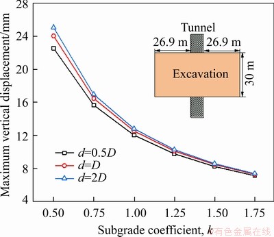
Figure 5 Difference in maximum vertical displacement versus subgrade coefficient
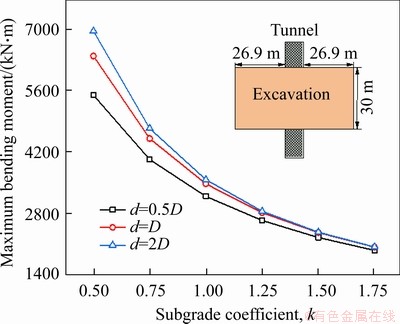
Figure 6 Difference in maximum bending moment versus subgrade coefficient
4.2 Offset distance
In this section, five different offset distances are selected from 0 to 40 m. Both Figures 7 and 8 show the displacement and bending moment of the metro tunnel, respectively. It is obvious that the maximum tunnel upward displacement occurs at the excavation center. Additionally, the tunnel displacement decreases with a greater distance along its longitudinal direction. The affected area of the tunnel caused by excavation starts at about 1.2 times of the excavation width away from the excavation center according to the results from the analytical solution. The positive hogging bending moment occurs at |x|<15 m and the negative sagging bending moment occurs at |x|>15 m. As offset distance x increases, the curve of the displacement and bending moment become much lower and flatter. It is observed that the tunnel is hardly affected by excavation when r0=40 m.
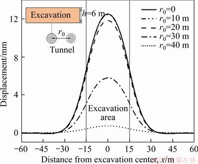
Figure 7 Displacement of metro tunnel at different offset distances
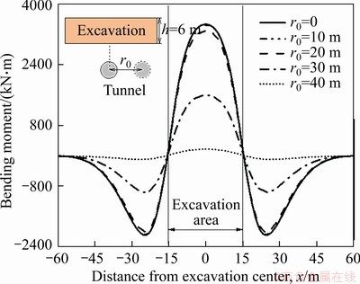
Figure 8 Bending moment of metro tunnel at different offset distances
Both Figures 9 and 10 show the maximum vertical displacement and the maximum bending moment of the tunnel in different offset distances, respectively. Five different values of equivalent flexural stiffness are considered in this section. The maximum tunnel upward displacement decreases slowly with an increase in the offset distance when 0 m≤r0≤20 m and it decreases rapidly with a greater offset distance when 20 m
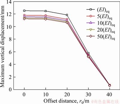
Figure 9 Difference in the maximum vertical displacement versus offset distance
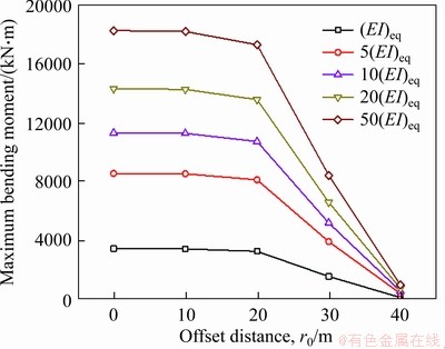
Figure 10 Difference in the maximum bending moment versus offset distance
4.3 Equivalent shear stiffness
Figure 11 presents the change in the maximum vertical displacement of the metro tunnel in different shear stiffness modified factor. The different depth of the excavation is considered in this section. The maximum vertical displacement of the metro tunnel decreases slowly as the modified factor grows from 0.05 to 10. It is indicated that the influence of the change in shear stiffness on tunnel displacement can be ignored. As for each modified factor, a greater tunnel displacement is obtained at a greater excavation depth. Much larger additional stress is acted on the tunnel with an increase in the excavation depth, which may cause damage to the tunnel structure.
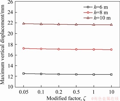
Figure 11 Difference in the maximum vertical displacement versus modified factor
Likewise, Figure 12 illustrates the variation in the maximum bending moment of the metro tunnel in relation to different shear stiffness modified factor. As the modified factor grows, the tunnel maximum bending moment increases. This reveals that a metro tunnel with a greater equivalent shear stiffness can suffer larger bending moment. Furthermore, the larger the excavation depth is, the larger the tunnel bending moment is. Anyway, the influence of the shear stiffness on the bending moment is more significant than that on the vertical displacement.
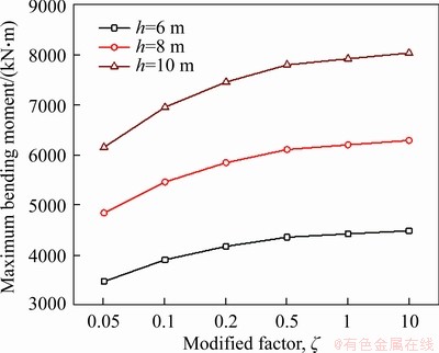
Figure 12 Difference in the maximum bending moment versus modified factor
5 Verification of proposed analytical solution
The additional stress in layered soil is compared with that in homogeneous soil by using elastic multilayer theory in this section. In addition, the results of the analytical solution are compared with the data measured from two classical cases so as to verify the effectuality of them.
5.1 Case I: Comparison of additional stress between layered soil and homogeneous soil
The plane area of the foundation pit is defined as 40 m long and 30 m wide in construction site, which consists of four soil layers. The excavation depth is set to be 10 m. The physical and mechanical parameters of soils are listed in detail in Table 1.
In this case, the vertical additional stress of longitudinal different points which are not only parallel to the short side of the foundation pit but also are located in 23 m below the ground surface is calculated in both layered soil and homogeneous soil, respectively. The soil modulus in homogeneous soil is calculated based on the method of POULOS et al [24]. Thus, elastic modulus and Poisson ratio are converted to be 102.8 MPa and 0.26, respectively.
Table 1 Physical and mechanical parameters of soils
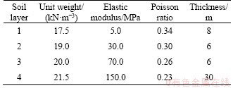
Figure 13 shows the distribution of additional stress of soil in layered soil and homogeneous soil, respectively. It is obvious that the value of additional stress in layered soil is beyond that in homogeneous soil surrounding the excavation center. The maximum value of additional stress in layered soil is equal to 149.1 kPa, which is 9.7% higher than that in homogeneous soil. In addition, additional stress in layered soil is smaller than that in homogeneous soil beyond 18 m away from the excavation center. This phenomenon can be explained well that stress concentration occurs in layered soil as the soil changes from soft to hard. Conversely, stress dispersion occurs when the soil changes from hard to soft. Furthermore, Boussinesq solution and Mindlin solution are usually used as the calculation method of soil additional stress at present, but both of them are limited to homogeneous soil. The calculation result of Boussinesq solution or Mindlin solution is equal to elastic multi-layer solution when the mechanical parameters of each soil layer are identical to others. In this case, elastic multi-layer solution can be replaced by Boussinesq solution or Mindlin solution. However, the deviation of calculation result between Burmister’s solution and Boussinesq solution is obvious if mechanical parameters of each soil layer are different from others. Thus, it is necessary to consider the variation of Elastic modulus and Poisson ratio while calculating the additional stress so as to obtain more accurate results.

Figure 13 Comparison of additional stress between layered soil and homogeneous soil
5.2 Case II: Underground project of Shanghai Daning Commercial Center
The project of Shanghai Daning Commercial Center is located in the west of Shanghai Metro Line 1, China. The excavation area is approximately equal to 44365 m2. Its area is of 240 m long and of 230 m wide. The excavation depth reaches 6.5 m. In addition, the depth of metro tunnels reaches 12 m, its longitudinal axis is parallel to the long side of the foundation pit. As is shown in Figure 14, the twin tunnels are observed with a clear horizontal distance of 7.8 m and the retaining structure is installed in the west of the downward-line tunnel with a clear horizontal distance of 5.45 m. Both two metro tunnels have an outer diameter of 6.2 m and an inner diameter of 5.5 m. Soil parameters of the construction site are obtained in detail by WANG et al [25]. The physical and mechanical properties of soil and the basic parameters of the segments and bolts of metro tunnels in Shanghai are listed in Tables 2 and 3, respectively. Considering the stiffness reduction of existing tunnels, equivalent flexural stiffness (EI)eq of metro tunnel is set to be 7.8×10⁷ kN・m2 based on the method presented by SHIBA et al [26]. The equivalent shear stiffness (λGA)eq is equal to 2.22×10⁶ kN/m according to Eq. (32).
As is shown in Figure 15, the distribution law of the curve drawn from the proposed method is consistent with the measured data in general, which is obtained from Ref. [12]. But the result calculated from Euler-Bernoulli beam lying on Winkler foundation is much higher than the measured data. Moreover, the curve obtained from the proposed method is narrower and much lower than that obtained from Euler-Bernoulli beam lying on Winkler foundation. The main reason for this phenomenon is that the shear action of metro tunnel can be analyzed using Timoshenko beam. That is to say, the application of Euler-Bernoulli beam without considering the shear effect overestimates the bending deformation of the metro tunnel, which is inconsistent with the deformation mode of the tunnel and further lead to both higher vertical displacement and wider affected area of the tunnel. Figure 16 shows the comparison of analytical results against the methodology of Euler-Bernoulli beam. The bending moment derived from Timoshenko beam are much lower than that of Euler-Bernoulli beam due to the decrease in flexural stiffness of the existing metro tunnel when considering the shear deformation.
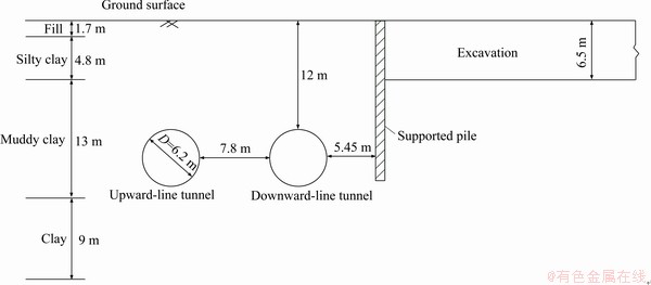
Figure 14 Cross-sectional view of foundation pit
Table 2 Physical and mechanical parameters of soils

Table 3 Detailed parameters of tunnel segments and bolts in Shanghai, China
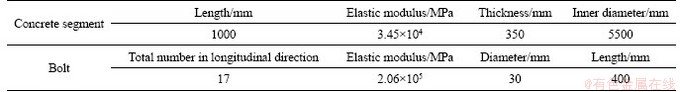
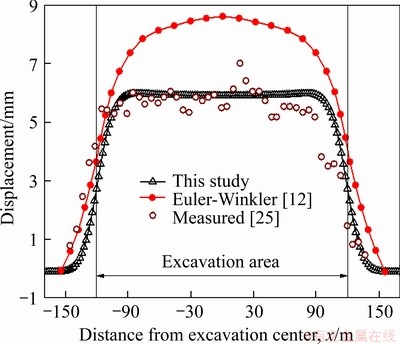
Figure 15 Comparison of vertical displacement of downward-line tunnel
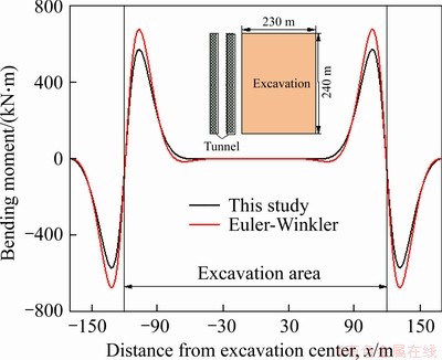
Figure 16 Comparison of bending moment in downward-line tunnel
Furthermore, Euler-Bernoulli beam is a continuous long beam with an infinite shear stiffness, which results in overestimating the values of the bending moments. In conclusion, the proposed method which does not only consider the change of Elastic modulus and Poisson ratio, but also the shear deformation of the metro tunnel can obtain more accurate results.
5.3 Case III: Underground project of Shanghai Yajule Square
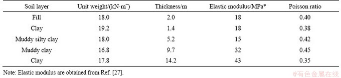
A section of the tunnels of metro line 1 in Shanghai locates beneath Yajule Square foundation pit, as is shown in Figure 17. The longitudinal axis of the metro tunnel is parallel to the long side of the foundation pit and the plane area of the excavation reaches 110 m×46 m. Besides, the cross-sectional view of the site is given in Figure 18. The excavation depth is 5 m and the depth of existing tunnel is approximately equal to 8.6 m. The diaphragm wall is installed in the east of the upward-line tunnel with a clear horizontal distance of 6.5 m. The outer diameter of the metro tunnel is 6.2 m in outer diameter. And the thickness of tunnel linings reaches 0.35 m. The equivalent shear stiffness (λGA)eq is 2.22×10⁶ kN/m and equivalent flexural stiffness (EI)eq is 7.8×10⁷ kN・m2. Strata parameters of construction site are listed in Table 4.
Figure 19 illustrates the comparison between the vertical displacement of upward-line tunnel using both the analytical solution and the measured values. The analytical results fit the trend showing with the measured data in general. There is a difference between the analytical results and the field measurements in values due to the protective measures taken during the excavation, such as zoned excavation with cross walls, piles tied to the walls and tunnel reinforcement, etc. However, the proposed analytical solution can not consider the resistance of the protective measures to the tunnel vertical displacement. In summary, the proposed method can be chosen as a quick and accurate prediction method for calculating the longitudinal deformation of the tunnel induced by excavation of foundation pit.
6 Conclusions
A theoretical prediction model is established in this paper to evaluate the mechanical behavior of existing metro tunnel caused by soil excavation in adjacent foundation pit. The conclusions are drawn as follows:
1) Instead of using Boussinesq solution or Mindlin solution, the additional stress induced by excavation of foundation pit on tunnel is calculated by using elastic multi-layer theory, in which the change of elastic modulus and Poisson ratio is considered. It is verified that the calculated results based on layered soil is more accurate in comparison with those based on homogeneous soil.
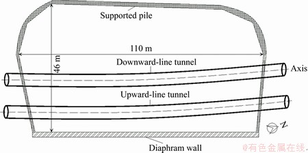
Figure 17 Plan view of foundation pit
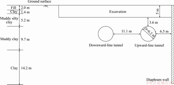
Figure 18 Cross-sectional view of foundation pit
Table 4 Properties of strata
2) In this analytical approach, the metro tunnel is regarded as a Timoshenko beam supported by Winkler foundation, in which the shear deformation of the tunnel is considered. Compared with two cases in Shanghai, China, calculated results using the analytical solution fit the measured data well. However, the influence of the shear deformation is omitted in Euler-Bernoulli beam, so the application of Euler-Bernoulli beam overestimates the longitudinal deformation of the metro tunnel due to adjacent excavation of foundation pit.
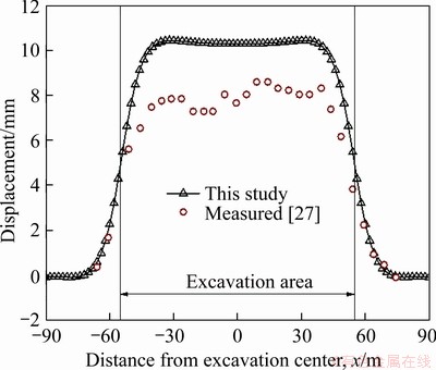
Figure 19 Comparison of vertical displacement of upward-line tunnel
3) Further parametric study considering the subgrade coefficient, the offset distance from the excavation center to tunnel longitudinal axis as well as the equivalent shear stiffness is performed to investigate the tunnel static behavior. The results show that increasing the subgrade coefficient or the offset distance reduces the tunnel vertical displacement effectively, but the change of shear stiffness hardly affects it. Meanwhile, a decrease in tunnel bending moment is observed if the subgrade coefficient or the offset distance increases. However, an increase in shear stiffness leads to a growth in bending moment.
Nonetheless, the nonlinearity of soil-tunnel interaction and the influence of horizontal additional stress on the tunnel static behavior caused by excavation of foundation pit are not considered in analytical solution at present. So, more comprehensive researches are needed to be conducted to improve the calculation result.
Contributors
The overarching research goals were developed by JIANG Jie. The analytical solution of longitudinal deformation of metro tunnel was obtained by QIU Ju-tao. QIU Ju-tao calculated the predicted displacement and analyzed the calculated results. The initial draft of the manuscript was written by QIU Ju-tao, ZHANG Yue-feng, and PAN Ying-dong. ZHOU Xiao-jun edited the draft of manuscript. All authors replied to reviewers’ comments and revised the final version.
Conflict of interest
QIU Ju-tao, JIANG Jie, ZHOU Xiao-jun, ZHANG Yue-feng and PAN Ying-dong declare that they have no conflict of interest.
References
[1] LEUNG C, MEGUID M A. An experimental study of the effect of local contact loss on the earth pressure distribution on existing tunnel linings [J]. Tunnelling and Underground Space Technology, 2011, 26(1): 139-145. DOI: 10.1016/ j.tust.2010.08.003.
[2] KUSUI A, VILLAESCUSA E, FUNATSU T. Mechanical behaviour of scaled-down unsupported tunnel walls in hard rock under high stress [J]. Tunnelling and Underground Space Technology, 2016, 60: 30-40. DOI: 10.1016/j.tust.2016. 07.012.
[3] DOLEZALOVA M. Tunnel complex unloaded by a deep excavation [J]. Computers and Geotechnics, 2001, 28(6, 7): 469-493. DOI: 10.1016/S0266-352X(01)00005-2.
[4] SHI Jiang-wei, NG C W W, CHEN Yong-hui. A simplified method to estimate three-dimensional tunnel responses to basement excavation [J]. Tunnelling and Underground Space Technology, 2017, 62: 53-63. DOI: 10.1016/j.tust.2016. 11.007.
[5] XIAO Xiao, LI Ming-guang, WANG Jian-hua, CHEN Jin-jian. Numerical evaluation of control measures for tunnel deformation induced by an oversized deep excavation [J]. Journal of Aerospace Engineering, 2018, 31(6): 04018109. DOI: 10.1061/(asce)as.1943-5525.0000906.
[6] CHHENG C, LIKITLERSUANG S. Underground excavation behaviour in Bangkok using three-dimensional finite element method [J]. Computers and Geotechnics, 2018, 95: 68-81. DOI: 10.1016/j.compgeo.2017.09.016.
[7] LI Ming-guang, XIAO Xiao, WANG Jian-hua, CHEN Jin-jian. Numerical study on responses of an existing metro line to staged deep excavations [J]. Tunnelling and Underground Space Technology, 2019, 85: 268-281. DOI: 10.1016/ j.tust.2018.12.005.
[8] ZHANG Zhi-guo, HUANG Mao-song, ZHANG Cheng-ping, JIANG Kang-ming, LU Ming-hao. Time-domain analyses for pile deformation induced by adjacent excavation considering influences of viscoelastic mechanism [J]. Tunnelling and Underground Space Technology, 2019, 85: 392-405. DOI: 10.1016/j.tust.2018.12.020.
[9] ZHANG Zhi-guo, HUANG Mao-song, XU Chen, JIANG Yun-juan, WANG Wei-dong. Simplified solution for tunnel-soil-pile interaction in Pasternak’s foundation model [J]. Tunnelling and Underground Space Technology, 2018, 78: 146-158. DOI: 10.1016/j.tust.2018.04.025.
[10] ZHANG Zhi-guo, HUANG Mao-song, XI Xiao-guang, YANG Xuan. Complex variable solutions for soil and liner deformation due to tunneling in clays [J]. International Journal of Geomechanics, 2018, 18(7): 04018074. DOI: 10.1061/ (asce)gm.1943-5622.0001197.
[11] ZHANG Jun-feng, CHEN Jin-jian, WANG Jian-hua, ZHU Yan-fei. Prediction of tunnel displacement induced by adjacent excavation in soft soil [J]. Tunnelling and Underground Space Technology, 2013, 36: 24-33. DOI: 10.1016/j.tust.2013.01.011.
[12] ZHANG Zhi-guo, HUANG Mao-song, WANG Wei-dong. Evaluation of deformation response for adjacent tunnels due to soil unloading in excavation engineering [J]. Tunnelling and Underground Space Technology, 2013, 38: 244-253. DOI: 10.1016/j.tust.2013.07.002.
[13] LI Peng, DU Shou-ji, WANG Yan-han, ZHAO Hong-hua. Timoshenko beam solution for the response of existing tunnels because of tunneling underneath [J]. International Journal for Numerical and Analytical Methods in Geomechanics, 2016, 40(5): 766-784. DOI: 10.1002/nag. 2426.
[14] LIANG Rong-zhu, XIA Tang-dai, HUANG Mao-song, LIN Cun-gang. Simplified analytical method for evaluating the effects of adjacent excavation on shield tunnel considering the shearing effect [J]. Computers and Geotechnics, 2017, 81: 167-187. DOI: 10.1016/j.compgeo.2016.08.017.
[15] LIANG Rong-zhu, WU Wen-bing, YU Feng, JIANG Guo-sheng, LIU Jun-wei. Simplified method for evaluating shield tunnel deformation due to adjacent excavation [J]. Tunnelling and Underground Space Technology, 2018, 71: 94-105. DOI: 10.1016/j.tust.2017.08.010.
[16] ZHANG Zhi-guo, ZHANG Cheng-ping, JIANG Kang-ming, WANG Zhi-wei, JIANG Yun-juan, ZHAO Qi-hua, LU Ming-hao. Analytical prediction for tunnel-soil-pile interaction mechanics based on kerr foundation model [J]. KSCE Journal of Civil Engineering, 2019, 23(6): 2756-2771. DOI: 10.1007/ s12205-019-0791-x.
[17] ZHANG Xue-min, OU Xue-feng, YANG Jun-sheng, FU Jin-yang. Deformation response of an existing tunnel to upper excavation of foundation pit and associated dewatering [J]. International Journal of Geomechanics, 2017, 17(4): 04016112. DOI: 10.1061/(asce)gm.1943-5622.0000814.
[18] MINDLIN R D. Force at a point in the interior of a semi-infinite solid [J]. Physics, 1936, 7(5): 195-202. DOI: 10.1063/1.1745385.
[19] BURMISTER D M. The general theory of stresses and displacements in layered soil systems. III [J]. Journal of Applied Physics, 1945, 16(5): 296-302. DOI: 10.1063/ 1.1707590.
[20] JIANG Jie. Nonlinear analysis of piled raft foundation in non-homogeneous soil [D]. Shanghai: Tongji University, 2008. (in Chinese)
[21] TIMOSHENKO S P. LXVI. On the correction for shear of the differential equation for transverse vibrations of prismatic bars [J]. The London, Edinburgh, and Dublin Philosophical Magazine and Journal of Science, 1921, 41(245): 744-746. DOI: 10.1080/14786442108636264.
[22] KLAR A, VORSTER T E B, SOGA K, MAIR R J. Soil―pipe interaction due to tunnelling: Comparison between Winkler and elastic continuum solutions [J]. Géotechnique, 2005, 55(6): 461-466. DOI: 10.1680/geot.2005.55.6.461.
[23] ZHANG Dong-mei, HUANG Zhong-kai, LI Zi-li, ZONG Xiang, ZHANG Dong-ming. Analytical solution for the response of an existing tunnel to a new tunnel excavation underneath [J]. Computers and Geotechnics, 2019, 108: 197-211. DOI: 10.1016/j.compgeo.2018.12.026.
[24] POULOS H G, DAVIS E H. Pile foundation Analysis and Design [M]. New York: Wiley, 1980: 93-100.
[25] WANG Wei-dong, SHEN Jian, WENG Qi-ping, WU Jiang-bin. Analysis and countermeasures of influence of excavation on adjacent tunnels [J]. Chinese Journal of Geotechnical Engineering, 2006, 28(S1): 1340-1345. (in Chinese)
[26] SHIBA Y, KAWASHIMA K, OBINATA N, KANO T. An evaluation method of longitudinal stiffness of shield tunnel linings for application to seismic response analyses [J]. Doboku Gakkai Ronbunshu, 1988(398): 319-327. DOI: 10.2208/jscej.1988.398_319.
[27] LI Jia-ping. Numerical analysis of influence of deep excavation on underlying metro tunnel [J]. Chinese Journal of Underground Space and Engineering, 2009, 5(S1): 1345-1348, 1360. (in Chinese)
(Edited by ZHENG Yu-tong)
中文导读
邻近基坑开挖引起既有隧道的纵向变形响应
摘要:基坑开挖将会对隧道周围土体造成扰动,进而导致隧道结构变形。如何准确地预测隧道的变形并采取措施最大程度减小隧道的上抬变形是一个难题。本文提出了一种新的简化分析方法,用于预测邻近基坑开挖卸荷引起的既有隧道纵向变形。通过引入弹性层状理论,得到了轴对称荷载作用下分层地基中的附加应力解。考虑隧道剪切变形的影响,将地铁隧道视为搁置于Winkler地基上的Timoshenko梁。基于该解析理论比较了分层地基和均质地基中由于开挖卸荷作用在隧道上的附加应力,并通过两个工程实例验证了解析理论的有效性。在此基础上,对基床系数、基坑开挖中心距隧道纵轴偏移距离和等效剪切刚度的变化引起的隧道变形响应进行了参数分析。研究成果可为类似工程提供理论依据。
关键词:地铁隧道;简化解析方法;附加应力;Timoshenko梁;Winkler地基
Foundation item: Project(51568006) supported by the National Natural Science Foundation of China; Project(2018JJA160134) supported by the Natural Science Foundation of Guangxi Province, China
Received date: 2020-11-09; Accepted date: 2021-02-02
Corresponding author: JIANG Jie, PhD, Professor; Tel: +86-18878884176; E-mail: jie_jiang001@126.com; ORCID: https://orcid.org/ 0000-0003-2667-6466; ZHOU Xiao-jun, PhD, Professor; Tel: +86-028-66364687; E-mail: zhouxjyu69@sina.com; ORCID: https://orcid.org/0000-0003-3892-8819

