Trans. Nonferrous Met. Soc. China 29(2019) 2245-2251
Is Ashby grain-boundary hardening model applicable for high strains?
S. MALOPHEYEV, I. VYSOTSKIY, S. MIRONOV, R. KAIBYSHEV
Belgorod National Research University, Pobeda 85, Belgorod 308015, Russia
Received 4 May 2019; accepted 23 July 2019
Abstract: This work was undertaken to evaluate the applicability of the Ashby grain-boundary hardening model for a high strain range. To this end, Al-Mg alloy with distinctly different grain sizes (~100 μm vs ~1 μm) was cold-rolled to a true strain of ~1.6 and the resulting dislocation densities were compared by using transmission electron microscopy. A minor difference revealed by the measurements suggested a violation of the Ashby’s model. This effect was attributed to a partial relaxation of strain constraints due to significant change of grain shape, development of texture and formation of pronounced substructure.
Key words: large plastic strain; strain compatibility; dislocations
1 Introduction
Due to difference in crystallographic orientation of neighboring grains, plastic deformation of a polycrystalline material should result in different slip activities across a grain boundary. To maintain compatibility of strain of the neighboring grains, an activation of additional slip systems is necessary. This increases total dislocation density. Accordingly, an equivalent plastic strain of a polycrystalline material generates a higher density of dislocations than that of a single crystal and this effect becomes more pronounced with reduction of a mean grain size. This conception is known as the Ashby grain-boundary hardening model and the additional dislocations are known as the geometrically-necessary dislocations (GND) [1]. The latter ones are distinguished from the “statistically- stored” dislocations (SSD) which are accumulated by random mutual trapping in pure single-crystals.
Considering significance of dislocation hardening for material strength, the above model is of particular importance for exploring a microstructure-strength relationship. Moreover, this conception has significantly contributed to our current understanding of deformation- induced microstructural changes. Specifically, the accommodation of the slip imbalance among the neighboring grains has been shown to eventually give rise to deformation-induced geometrically-necessary boundaries [2-4]. The subsequent evolution of such boundaries leads to grain subdivision [5-8] and may provide a formation of ultrafine-grained structure [9].
It is worth noting that large plastic deformations may considerably alternate morphology as well as crystallographic orientation of grains and thus influence the strain compatibility requirements. Due to geometrical effect of strain, for instance, the original equaixial grains may transform into heavy elongated lamellar or fiber-shaped grains. This may significantly reduce the number of grain neighbors and thus partially relax the strain constraints [10]. On the other hand, a development of deformation texture virtually implies a convergence of crystallographic orientations which may equilibrate slip activity in the neighboring grains. All these issues suggest a deviation of the material behavior from the Ashby model in the high strain range.
The validity of this model for the true strains as high as ~0.46 has been recently examined by using electron backscatter diffraction (EBSD) [11-16] techniques. It has been found that the GND density followed the Ashby model quite well. Specifically, the density of such dislocations increased linearly with strain [11,12,14] and was relatively high near grain boundaries and triple junctions or within relatively fine grains [11,14-16]. On the other hand, a reliability of the Ashby theory at essentially larger strains has never been examined, to the best of the authors’ knowledge. The present work was undertaken in an attempt to fill this gap in our knowledge. To this end, two material conditions with distinctly different grain sizes were cold rolled to a true strain of ~1.6 and the accumulated dislocation densities were directly compared.
2 Experimental
The program material comprised Al-Mg alloy with measured chemical composition shown in Table 1. The material was produced by semi-continuous casting followed by solution heat treatment at 360 °C (~0.68Tm, where Tm denotes the melting point) for 8 h and subsequent extrusion at 380 °C (~0.70Tm) with a 4:1 reduction. The resulting microstructure was dominated by elongated grains of ~100 μm long and ~30 μm thick (Fig. 1). In greater detail, the microstructure has been characterized elsewhere [17]. This material condition was referred throughout as coarse-grained material.
Table 1 Measured chemical composition of program material (wt.%)
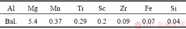
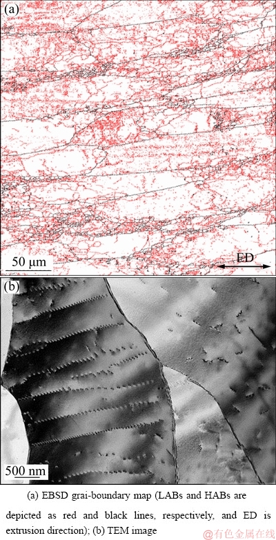
Fig. 1 Typical microstructures in coarse-grained material condition
To produce a material condition with distinctly different grain size, the coarse-grained material was subjected to equal-channel-angular pressing (ECAP) via route BC. ECAP was performed at 300 °C (~0.61Tm) to a true strain of ~12 using isothermal die with a 90° square channel. Following ECAP, the material was immediately quenched in water. The produced microstructure was dominated by nearly equiaxed grains of ~1 μm in diameter (Fig. 2). In more detail, the ECAP process as well as the produced microstructure has been described elsewhere [18]. This material condition was referred to as fine-grained material.

Fig. 2 Typical microstructures in fine-grained material condition
To investigate the reliability of the Ashby grain-boundary hardening model for the high-strain range, materials under both conditions were rolled at ambient temperature to 80% of thickness reduction (true strain of about 1.6). The rolling direction was selected parallel to either extrusion direction or longitudinal axis of ECAP billet. The typical flat-rolling convention was adopted in this work, i.e., the rolling, transverse and thickness/normal directions were denoted as RD, TD and ND, respectively.
The deformation-induced microstructures were examined by electron backscatter diffraction (EBSD) and transmission electron microscopy (TEM) techniques. The suitable surface finish for microstructural observations was obtained by electro-polishing in a solution of 25% nitric acid in ethanol with an applied potential of 20 V. EBSD was employed for characterization of broad aspects of the evolved microstructures whereas TEM was used for direct observations of dislocation structures.
The EBSD analysis was conducted using a FEI Quanta 600 field-emission-gun scanning electron microscope equipped with TSL OIMTM software. Depending on particular microstructure examined, the scan step size of 0.2 μm or 0.05 μm was used. Considering significant difference in grain size between two studied material conditions (i.e., 1 μm vs 100 μm), it was decided to be impractical to use the same scan step size for EBSD mapping. To improve reliability of EBSD data, small grains comprising three or fewer pixels were automatically removed from the acquired EBSD maps using the grain-dilation option of the TSL software. In addition, a lower-limit boundary-misorientation cut-off was used to eliminate spurious boundaries caused by orientation noise. A 15° criterion was employed to differentiate low-angle boundaries (LABs) versus high- angle boundaries (HABs). TEM study was performed using a JEM-2100EX TEM operating at 200 kV. Density of free dislocations was measured on TEM micrographs by the linear intercept method [19] and by applying the equation of ρ=2N/(Lt), where N is the number of intersections with dislocations made by intercept lines of length L on an TEM image, and t is the foil thickness.
3 Results
3.1 Microstructure
The original (unprocessed) EBSD maps taken from materials under both conditions are shown in Fig. 3. The typical microstructures produced during heavy cold rolling of the coarse- and fine-grained materials are shown in Fig. 4.
EBSD measurements showed that the resulting microstructures in both studied material conditions were dominated by ribbon-shaped grains which contained developed substructure. In the fine-grained condition, some evidences for shear banding were also seen (Fig. 4(b)). On a grain scale, the deformation-induced substructures were often comprised by two intersection sets of LABs inclined at ~±30° to the RD; this effect was most pronounced in the coarse-grained material (Fig. 4(a)).
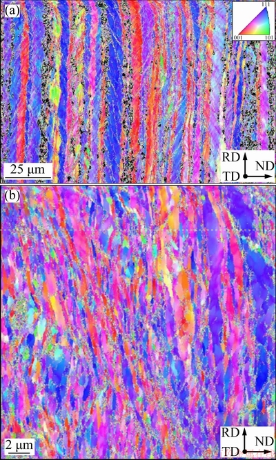
Fig. 3 Original (unprocessed) EBSD orientation maps taken from cold-rolled coarse-grained material (a) and fine-grained material (b) (Grains are colored according to their crystallographic orientations relative to RD; color code triangle is shown in top right corner of (a))
From TEM observations, these boundary sets were composed of bands of nearly parallel LABs with boundary spacing of ~0.2 μm in the coarse-grained condition (Fig. 4(a)) or ~0.1 μm in the fine-grained condition (Fig. 4(b)). The development of such microstructures is well documented for cold-rolled cubic metals and is usually attributed to the grain subdivision mechanism [7-9].
3.2 Misorientation
Attempting to get additional insight into the LAB substructure, misorientation data have been extracted from EBSD maps and arranged as misorientation-angle distributions in Fig. 5. It should be noted that misorientation data were expressed in terms of grain-boundary density, i.e., the measured grain- boundary length for a given misorientation angle divided by the area of the EBSD map. From prior experience, this metric provides a direct comparison of grain-boundary characteristics, thus enabling more reliable interpretation of the underlying physical mechanisms.
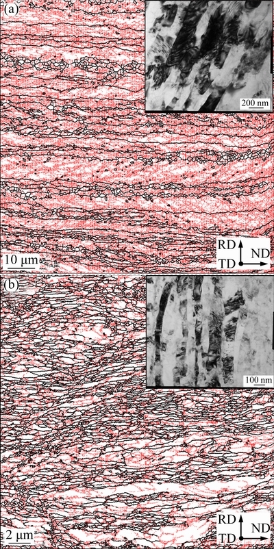
Fig. 4 EBSD grain-boundary maps and TEM images showing typical microstructure of cold-rolled coarse-grained material (a) and cold-rolled fine-grained material (b) (TEM images are given as inserts; In EBSD maps, LABs and HABs are depicted as red and black lines, respectively)
As expected, the cold rolling resulted in significant enlargement of LAB density. This presumably evidenced that a significant portion of dislocations was rearranged into dislocation boundaries. In addition to the formation of LABs, a relatively-homogeneous increase of HAB area was observed in a wide range of misorientations between ~15° and 62.8° after rolling in both material conditions studied. This phenomenon presumably resulted from the geometrical effect of strain which compressed the original grains along the ND and thus increased their boundary area in the longitudinal section of the rolled sheets (Fig. 4).
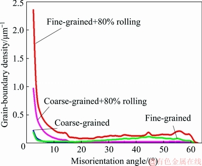
Fig. 5 Effect of cold rolling on misorientation-angle distributions
3.3 Dislocation density
To evaluate the reliability of the Ashby’s model, the density of free dislocations was TEM-measured in both rolled materials and the results obtained were summarized in Table 2. Kernel-average-misorientation EBSD maps for examined materials under both conditions are shown in Fig. 6. Considering a developed LAB substructure evolved in both studied conditions, the density of dislocations stored in dislocation boundaries was also estimated by using the classical Read-Shockley relation [20] ρLABs=αθ/(bd), where α is constant (taken to be 1 for both material conditions), θ is the mean LAB misorientation (taken to be 1° in both cases), b is the Burgers vector magnitude (=0.286 nm), and d is the mean LAB spacing. The calculation results are also shown in Table 2. It is clear that total dislocation densities in both studied material conditions were nearly the same. This may indicate a violation of Ashby’s law in the high-strain range.
On the other hand, it is worth noting that TEM measurements give a total dislocation density, i.e., a sum of the GND and the SSD. In the high-strain range, the total density of dislocation in the coarse-grained materials (≥100 μm) is believed to be dominated by the SSD whereas that in the fine-grained materials (≤2 μm) is swamped by the GND [1]. Considering a well-known saturation of dislocation density with strain, the above circumstance may also be a possible explanation for the minor difference between two studied material conditions revealed in the present study (Table 2).
Table 2 Evaluation of dislocation density
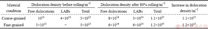
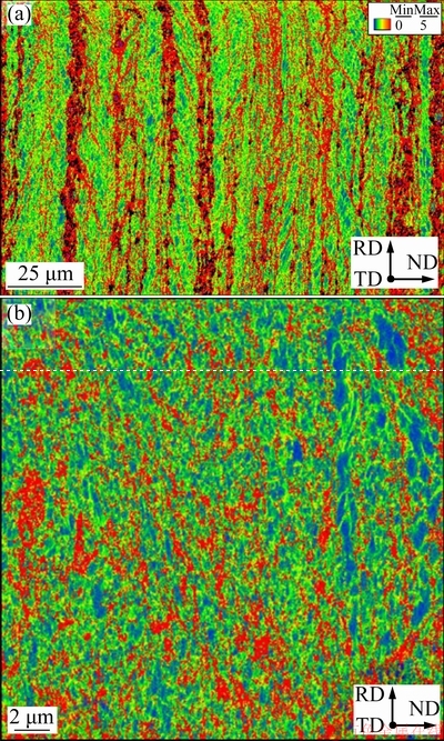
Fig. 6 Kernel-average-misorientation (KAM) EBSD maps taken from cold-rolled coarse-grained material (a) and fine-grained material (b) (KAM color code is shown in top right corner of (a))
4 Discussion
4.1 Possible reasons for violation of Ashby’s law
The Ashby’s model is based on compatibility of strain of neighboring grains. This effect is obviously a function of a number of the neighboring grains (i.e., a grain shape) as well as a difference of their crystallographic orientations.
According to a classical von Mises criterion, five independent slip systems are required to accommodate arbitrary strain. However, KOCKS and CANOVA [10] have shown that, under some specific conditions, strain compatibility can be achieved with fewer number of slip systems. For example, during compression of flat grains having random crystallographic orientations, the activation of the five systems is only needed at the periphery of each grain, whereas the bulk material may deform on only three independent slip systems [10]. This effect was associated with significantly reduced number of grain neighbors in the case of flat grains as compared to that of equiaxed grains (i.e., 2 versus 14). Therefore, a development of the ribbon grain structure during rolling (Fig. 4) may partially relax the strain constraints and thus violate the Ashby’s model.
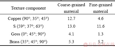
The above phenomenon may be enhanced by the formation of deformation texture, i.e., virtually, a convergence of crystallographic orientations of neighboring grains. To evaluate this possibility, orientation data were derived from EBSD maps and arranged as orientation distribution functions in Fig. 7. The volume fractions of principal textural components were summarized in Table 3. It is seen that both studied material conditions were characterized by typical rolling texture and this may also contribute to the observed deviation from the Ashby’s model.
Fig. 7 Selected sections (φ2=0°, 45° and 65°) of orientation distribution functions showing texture in cold-rolled coarse- grained material (a) and fine-grained material (b)
Table 3 Fractions of textural components (%)
An additional factor contributing to the above effect may be the formation of developed substructure in both materials (Fig. 4) which should also promote a decoupling of the dislocation density from the original grain size.
The above arguments are in the line with recently-reported saturation of the GND density at ~1015 m-2 at true strains exceeding ~0.1 [11,12,14].
4.2 Limitations of present work
On the other hand, considering complexity of the microstructures produced during heavy deformation (Fig. 4), reliable measurements of dislocation density is challenging. There is a possibility, therefore, that the dislocation densities evaluated in the current work (Table 2) were incorrect and thus the Ashby’s model was actually valid for the high strain range. The possible sources for the errors are briefly considered below.
First and foremost, the pronounced strain fields present in the deformation-induced microstructures (TEM micrographs in Fig. 4), significantly complicate the measurements of dislocation density.
Moreover, as mentioned in Section 3.2, the area of original grain boundaries was significantly enlarged during rolling due to the geometrical compression of original grains in proportion of the imposed strain (Fig. 5). Specifically, the measured boundary density in the fine-grained condition was nearly doubled whereas that in the coarse-grained material increased by 7 times. This phenomenon is thought to be related with the absorption of dislocations by the grain boundaries. If so, this should substantially degrade the measurement accuracy.
As pointed by HUMPHREYS [21], significant portion of dislocations in heavily-deformed aluminum is stored in dislocation boundaries. This was indeed observed in the current work (Table 2). However, uncertainties of the Read-Shockley equation, specifically α and θ, considerably complicate the evaluation of the dislocation density.
Therefore, the suggested violation of the Ashby model warrants further confirmation.
5 Conclusions
The applicability of the Ashby grain-boundary hardening model for a high strain range was evaluated. To this end, materials under two conditions with distinctly different grain sizes (~100 μm vs 1 μm) were cold-rolled to a true strain of ~1.6 and the accumulated dislocation densities were directly compared. In both cases, the dislocation densities were found to be nearly the same and therefore the Ashby’s model may violate at high strains. This effect was attributed to partial relaxation of strain constraints due to (1) an extensive flattering of grains during rolling and the concomitant reduction of grain neighbors as well as (2) a formation of deformation texture. Moreover, this effect was presumably also influenced by a formation of developed substructure within grains. On the other hand, the challenges of the reliable measurement of dislocation density after high strains as well as difficulties with their interpretation in terms of GND or SSD necessitate a further work in this area.
Acknowledgements
This study was financially supported by the Russian Science Foundation, grant No. 18-79-10174. The authors also would like to thank the personnel of the Joint Research Centre at Belgorod National Research University for technical assistance during microstructural observations.
References
[1] ASHBY M F. The deformation of plastically non-homogeneous materials [J]. The Philosophical Magazine, 1970, 21: 399-424.
[2] KUHLMANN-WILSDORF D, HANSEN N. Geometrically necessary, incidental and subgrain boundaries [J]. Scripta Metallurgica et Materialia, 1991, 25: 1557-1562.
[3] RYBIN V V, ZISMAN A A, ZOLOTOREVSKIY N Y. Junction disclinations in plastically deformed crystals [J]. Acta Metallurgica et Materialia, 1993, 41: 2211-2217.
[4] PANTLEON W, HANSEN N. Disorientations in dislocation boundaries: Formation and spatial correlation [J]. Materials Science and Engineering A, 2001, 309-310: 246-250.
[5] BAY B, HANSEN N, KUHLMANN-WILSDORF D. Deformation structures in lightly rolled pure aluminium [J]. Materials Science and Engineering A, 1989, 113: 385-397.
[6] BAY B, HANSEN M, HUGHES D A, KUHLMANN-WILSDORF D. Overview No. 96 evolution of f.c.c. deformation structures in polyslip [J]. Acta Metallurgica et Materialia, 1992, 40: 205-219.
[7] HUGHES D A, HANSEN N. High angle boundaries formed by grain subdivision mechanisms [J]. Acta Materialia, 1997, 45: 3871-3886.
[8] HANSEN N, JENSEN D J. Development of microstructure in FCC metals during cold work [J]. Philosophical Transactions of the Royal Society of London A, 1999, 357: 1447-1469.
[9] PRANGNELL P B, BOWEN J R, APPS P J. Ultra-fine grain structures in aluminium alloys by severe deformation processing [J]. Materials Science and Engineering A, 2004, 375-377: 178-185.
[10] KOCKS U F, СANOVA G R. How many slip systems and which? [C]// HANSEN N, HORSEWELL A, LEFFERS T, LILHOLT H. Deformation of polycrystals: Mechanisms and microstructures. Roskilde: Riso National laboratory, 1981: 35-38.
[11] JIANG J, BRITTON T B, WILKINSON A J. Evolution of dislocation density distributions in copper during tensile deformation [J]. Acta Materialia, 2013, 61: 7227-7239.
[12] ZHU C, HARRINGTON T, GRAY III G T, VECCHIO K S. Dislocation-type evolution in quasi-statically compressed polycrystalline nickel [J]. Acta Materialia, 2018, 155: 104-116.
[13] ZHU C, HARRINGTON T, LIVESCU V, GRAY III G T, VECCHIO K S. Determination of geometrically necessary dislocations in large shear strain localization in aluminum [J]. Acta Materialia, 2016, 118: 383-394.
[14] KUNDU A, FIELD D P. Influence of plastic deformation heterogeneity on development of geometrically necessary dislocation density in dual phase steel [J]. Materials Science and Engineering A, 2016, 667: 435-443
[15] LITTLEWOOD P D, BRITTON T B, WILKINSON A J. Geometrically necessary dislocation density distributions in Ti-6Al-4V deformed in tension [J]. Acta Materialia, 2011, 59: 6489-6500.
[16] LITTLEWOOD P D, WILKINSON A J. Geometrically necessary dislocation density distributions in cyclically deformed Ti-6Al-4V [J]. Acta Materialia, 2012, 60: 5516-5525.
[17] MALOPHEYEV S, KULITSKIY V, MIRONOV S, ZHEMCHUZHNIKOVA D, KAIBYSHEV R. Friction-stir welding of an Al-Mg-Sc-Zr alloy in as-fabricated and work-hardened conditions [J]. Materials Science and Engineering A, 2014, 600: 159-170.
[18] MALOPHEYEV S, KULITSKIY V, KAIBYSHEV R. Deformation structures and strengthening mechanisms in an Al-Mg-Sc-Zr alloy [J]. Journal of Alloys and Compounds, 2017, 689: 957-966.
[19] HIRSCH P B, HOWIE A, NICHOLSON R B, PASHLEY D W, WHELAN M J. Electron microscopy of thin crystals [M]. 2nd ed. Malabar: Krieger Publishing, 1977.
[20] READ W T, SHOCKLEY W. Dislocation models of crystal grain boundaries [J]. Physical Review, 1950, 78: 275-289.
[21] HUMPHREYS F J. A unified theory of recovery, recrystallization and grain growth, based on the stability and growth of cellular microstructures―I. The basic model [J]. Acta Materialia, 1997, 45: 4231-4240.
Ashby晶界强化模型适用于高应变吗?
S. MALOPHEYEV, I. VYSOTSKIY, S. MIRONOV, R. KAIBYSHEV
Belgorod National Research University, Pobeda 85, Belgorod 308015, Russia
摘 要:为了评估Ashby晶界强化模型在高应变范围内的适用性,将具有不同晶粒尺寸的Al-Mg合金(~100 μm与~1 μm)冷轧至真应变约为1.6,并采用透射电镜观察比较两种合金的位错密度。测量结果显示的微小差异表明其违背了Ashby模型,这是由晶粒形状的显著变化、织构演化和形成明显的亚结构等因素造成应变约束的局部松弛导致。
关键词:大塑性应变;应变协调性;位错
(Edited by Bing YANG)
Corresponding author: S. MIRONOV; E-mail: mironov@material.bsu.edu.ru
DOI: 10.1016/S1003-6326(19)65130-7

