J. Cent. South Univ. (2016) 23: 430-439
DOI: 10.1007/s11771-016-3088-y

Experimental and numerical study on crack propagation in pre-cracked beam specimens under three-point bending
Hadi Haeri
Department of Mining Engineering, Bafgh Branch, Islamic Azad University, Bafgh, Iran
 Central South University Press and Springer-Verlag Berlin Heidelberg 2016
Abstract: A simultaneous experimental and numerical study on crack propagation in the pre-cracked beams specimens (concrete-like materials) is carried out using three-point bending flexural test. The crack propagation and coalescence paths of internal cracks in side beam specimens are experimentally studied by inserting double internal cracks. The effects of crack positions on the fracturing path in the bridge areas of the double cracked beam specimens are also studied. It has been observed that the breaking of concrete-like cracked beams specimens occurs mainly by the propagation of wing cracks emanating from the tips of the pre-existing cracks in the numerical and experimental analyses, respectively. The same specimens are numerically simulated by an indirect boundary element method (IBEM) known as displacement discontinuity method (DDM) using higher displacement discontinuity. These numerical results are compared with the existing experimental results. This comparison illustrates the higher accuracy of the results obtained by the indirect boundary element method by using only a small number of elements compared with the discrete element method (PFC2D code).
Key words: double internal cracks; concrete-like specimens; crack propagation
1 Introduction
Concrete is one of the most widely used construction materials. It has good compressive strength, durability, fire resistance and can be cast to fit any structural shape. The different kinds of defects called internal cracks produce in concrete in the first hours and even before being placed under loading condition. These defects may extremely reduce the strength of concrete structure. A crack may act as a nucleus of initiation and extension of new cracks in concrete which may propagate and coalesce with other cracks and further reduce the strength and the stiffness of the concrete. The mechanical characteristics of concrete may be affected by the mechanical behaviors of the defects and internal cracks/flaws.
In the crack propagation process of brittle materials such as concrete-like specimens (double cracked beam specimens are specially prepared from a proper mixture of Pozzolana Portland Cement (PPC), sand and water), the tensile cracks (wing cracks) are commonly produced in three-point flexure bending tests, which are observed originating from the original tips of pre-existing cracks.
ZENG et al [1] predicted the fracture processes of asphalt mixture beam specimens under three-point bending by using a damage model. They analyzed the effects of crack location and coarse aggregate distribution on damage evolution behavior and crack propagation path. It has also been shown that these simulation results are in good agreement with their corresponding experimental results. WANG et al [2] studied the shear deformation in reinforced concrete beam (BRC) specimens considering low span-effective depth ratios. A multi-angle truss model was proposed to predict the diagonal crack angles. The influence of the bending moment variation along the span on the diagonal crack angles is also considered in analysis and finally experimental results are compared with numerical predictions of diagonal crack angles.
OZCEBE [3] utilized a technological approach to study the failure of T-beams and RUIZ and CARMONA [4] used rectangular beams and one type of T-beams to study the influence of the shape of the crack propagation. On the other hand, RUIZ et al [5] showed theoretically the existence of a secondary peak in the load record due to the beginning of the propagation of the crack through the head of the beam.
Many experimental works have also been devoted to study the crack initiation, propagation, interaction and eventual coalescence of the pre-existing cracks in specimens of various substances, including natural rocks or rock-like materials under compressive loading [6-21].Finite element method (FEM), boundary element method (BEM) and discrete element method (DEM) have been used for the simulation of crack propagation in brittle solids such as concrete and rock.
The three classical fracture initiation criteria, ie, 1) the maximum tangential stress (s��-criterion), 2) the maximum energy release rate (G-criterion) and 3) the minimum energy density criterion (S-criterion) are being used in the fracture mechanics literature to study the crack propagation mechanism of brittle materials [22]. Some mixed mode or modified mode of these criteria (such as F-criterion which is a modified energy release rate criterion proposed by SHEN and STEPHANSSON [23]) may also be used to describe the fracturing process of brittle solids [24-27]. Based on the numerical and analytical methods, several computer codes were proposed by the researchers to model the breaking mechanism of brittle materials such as rocks, e.g. FROCK code [28], rock failure process analysis (RFPA2D) code [29], 2D particle flow code (PFC2D)[8].
In this work, the crack propagation mechanism of pre-cracked concrete-like specimens is investigated experimentally by carrying out some three-point bending tests on the specially prepared samples (using a proper mixture of PPC, fine sands and water) in the laboratory. The same specimens are numerically simulated by a modified higher order displacement discontinuity code that is a special version of dual boundary element method (DBEM). This computer code uses a cubic variation of displacement discontinuities along each boundary element containing four equal sub-elements [30]. The linear elastic fracture mechanics (LEFM) concepts (by computing the Mode I and Mode II stress intensity factors (SIFs)) and s-criterion has been implemented in the computer code to predict the possibility of crack propagation and estimate the crack initiation direction.
In the present work, a testing technique (i.e. three- point bending flexural test) has been performed to study the fracturing process of concrete specimens. This test is very sensitive to loading geometry. Failure mode is a function of the eccentricity of the applied compressive load in pre-cracked/specimens. The effects of crack positions on the fracturing path in the bridge areas of the double cracked beam specimens are also studied. Results of the numerical analysis are compared with the
experimental results. The comparison shows that the numerical results are well fitted with experimental results and approve the accuracy and effectiveness of the proposed study of the concrete fracturing process under three-point bending condition.
2 Experimental studies
The three-point bending flexural test generates the conditions of mixed mode I/II and allows the propagation of tensile and shear cracks. These cracks propagated and the failure of beam specimens normally occurred in the flexure failure mode rather than shear failure mode which is a function of the eccentricity of the applied compressive load.
The three-point bending flexural test configuration allows the propagation of cracks under mode I, mode II and mixed mode I/II loading (tension (opening) and shear (sliding of the faces)) according to fracture mechanic concepts [31-32].
2.1 preparation of pre-cracked specimen and its mechanical properties
The pre-cracked beam specimens of quasi-brittle materials (like concrete) with 50 cm��10 cm��10 cm (50 cm of length, 10 cm of width, 10 cm of thickness) are specially prepared from a mixture of Portland Pozzolana cement (PPC), fine sands and water. Table 1 gives the ingredient ratios and mechanical properties of the prepared concrete (rock-like) specimens tested in the laboratory before inserting the cracks.
Three-point bending tests were conducted on concrete beam specimens (each specimen contained two internal cracks). These cracks were created by inserting thin metal shims with different positions and 1 mm thickness into the specimens (during the specimens cast in the mold) (Fig. 1).
In the laboratory, various types of the specially prepared double cracked beam (DCB) specimens were tested to study the crack propagation process of the pre-cracked brittle solids.
The cracked beam specimens containing two internal cracks of different positions were prepared and tested in a geotechnical laboratory. The compressive line loading, F, was applied and the loading rate was kept at 0.5 MPa/s during the tests.
Two cracks with different positions (non-overlap/overlap cracks) for double cracked beam specimens are shown in Fig. 2. The pre-existing double cracks inside the beam are located indifferent positions.
Table 1 Ingredient ratios (%) and mechanical properties of concrete specimens

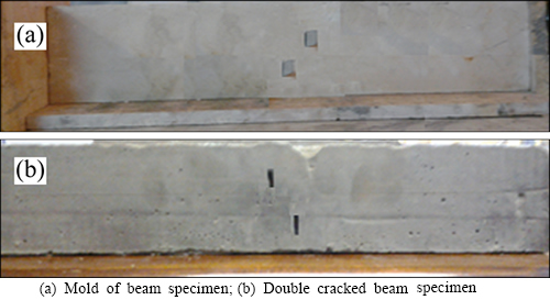
Fig. 1 typical concrete-like specimen prepared for laboratory test:
2.2 fracturing process of double cracked beam specimens
Some experimental bending tests of double cracked beam (DCB) specimens were carried out in the laboratory by three-point bending technique. The pre-existing double cracks inside the beam were located at indifferent positions. These results compared for the four cases are shown in Figs. 3(a)-(d). Figures 3(a)-(d) illustrate the fracturing paths of non-overlapped and overlapped crack.
For the four cases shown in Figs. 3(a)-(d), the wing cracks initiated at the tip of the two original cracks and the cracks coalesced with each other at the propagating crack tips. These wing cracks developed in a direction (approximately) vertical to the direction of compressive line load (central loading).
3 Numerical simulation of experimental tests
The displacement discontinuity method (DDM) which is a version of indirect boundary element method (IBEM) and implements a higher order displacement discontinuities variation along each boundary elements in a two dimensional elastostatic body [33-34] is employed to simulate the experimental testing specimens used in this work.
It has been shown that the higher order displacement discontinuity method gives an accurate solution of normal displacement discontinuity (crack opening displacement) and shear displacement discontinuity (crack sliding displacement) near the crack ends [22, 33].
The mode I and mode II stress intensity factors (SIFs) can be formulated based on these discontinuities using the linear elastic fracture mechanics (LEFM) principles [34]. This method gives a very accuracy when the special crack tip elements can be used to account for the singularities of stress and displacement fields near the crack ends [30]. This method also reduces the boundary meshes (elements) as the two sides of the line cracks are simultaneously discretized with similar boundary conditions [30].
3.1 Higher order displacement discontinuity method (HODDM)
The displacement discontinuities along the boundary of the problem can be achieved more accurately by using higher order displacement discontinuity (HODD) elements (e.g. quadratic or cubic HODD elements) in the solution of cracked elastostatic bodies.
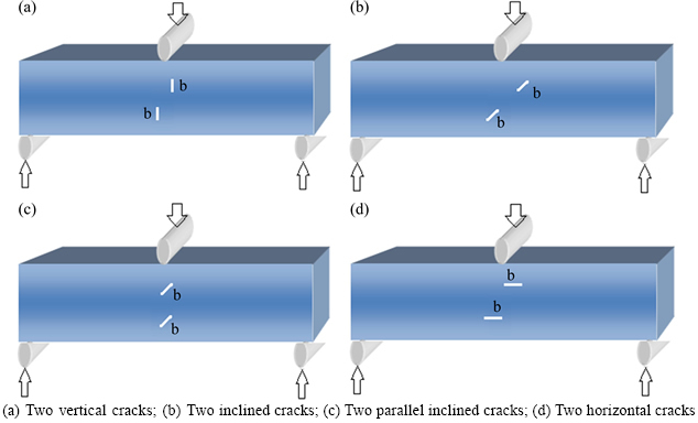
Fig. 2 crack geometries showing different positions for double cracked beam (DCB) specimens:
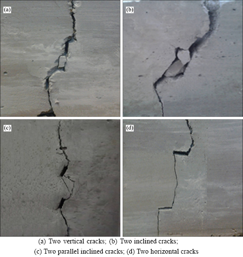
Fig. 3 Cracking patterns in double cracked beam specimens containing different crack positions:
A cubic (DD) element (Dk(��)) is divided into four equal sub-elements of which each sub-element contains a central node for the nodal displacement discontinuity (DD) evaluated numerically (the opening displacement discontinuity Dy and sliding displacement discontinuity Dx) [30].
 (1)
(1)
where


 and
and are the cubic nodal displacement discontinuities and,
 (2)
(2)
are the cubic collocation shape functions using a1=a2= a3=a4. A cubic element has 4 nodes, which are the centers of its four sub-elements shown in Fig. 4.
In Fig. 4, a cubic (DD) element is divided into four equal sub-elements (each sub-element contains a central node for the nodal displacement discontinuities evaluated numerically) [30].
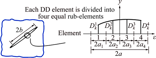
Fig. 4 Cubic collocations for higher order displacement discontinuity variation
The potential functions f(x,y), and g(x,y) for the cubic case can be found as
 (3)
(3)
Inserting the common displacement discontinuity function, Dk(��) (eq. (1)) in eq. (3) gives:
 (4)
(4)
Inserting the shape functions 

 and
and  (eq. (2)) in eq. (4), the integrals I0, I1 , I2 and I3 are expressed as follows:
 (5)
(5)
Since the singularities of the stresses and displacements near the crack ends may reduce their accuracies, special crack tip elements are used to increase the accuracy of the DDs near the crack tips [30]. As shown in Fig. 5, the DD variation for three nodes can be formulated using a special crack tip element containing three nodes (or having three special crack tip sub-elements).
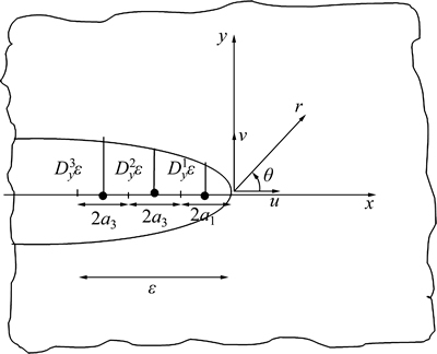
Fig. 5 A special crack tip element with three equal sub-elements

 (6)
(6)
where the crack tip element has a length a1=a2=a3.
Considering a crack tip element with the three equal sub-elements (a1=a2=a3), the shape functions ��C1(��), ��C2(��) and ��C3(��) can be obtained as
 (7)
(7)
 (8)
(8)
Inserting the common displacement discontinuity function, Dk(��) (eq. (6)) in eq. (8) gives:

 (9)
(9)
Inserting the shape functions, ��C1(��), ��C2(��) and ��C3(��) (eq. (7)) in eq. (9) after some manipulations and rearrangements, the following three special integrals are deduced as
 (10)
(10)
Based on the linear elastic fracture mechanics (LEFM) principles, the mode I and mode II stress intensity factors KI and KII, (expressed in MPa��m1/2) can be written in terms of the normal and shear displacement discontinuities obtained for the last special crack tip element as [30]
 (11)
(11)
where �� is the shear modulus and �� is Poisson ratio of the brittle material.
3.2 Cracking boundaries for double cracked beam specimens
In the simulation of the double cracked beam specimens, the discretization of the cracking boundaries has been accomplished by using 38 cubic elements along beam specimens and 8 cubic elements along each pre-existing crack (Fig. 6). In the numerical modeling, the ratio of crack tip length, L, to the crack length, b, is 0.2 (L/b=0.2) and three special crack tip elements are used.
3.3 Numerical simulation of experimental works
Although the experiments carried out in this study are in three-dimension, the numerical simulation of them is done by a two-dimensional higher order displacement discontinuity briefly explained in the previous section. This numerical analysis is based on the two-dimensional plain strain conditions which are more usual in fracture mechanics literature.
The cracks propagation and cracks coalescence in cracked beam specimens of concrete-like brittle materials are numerically studied and these results are compared with the corresponding results observed experimentally in Figs. 7(a)-(d) and Figs. 7(a)-(d).
The double cracked beam specimens (already shown in Figs. 7(a)-(d)) are simulated by a modified higher order displacement discontinuity code and the crack propagation paths are graphically shown in Figs. 7(a)-(d). In the present numerical simulations, the mode I and mode II stress intensity factors (SIFs) proposed by IRWIN [35] are estimated based on LEFM approach. A modified higher order displacement discontinuity code is provided using the maximum tangential stress criterion given by ERDOGAN and SIH [36] in a stepwise procedure so that the propagation paths of the propagating wing cracks are estimated. As shown in Fig. 7, the simulated propagation paths are in good agreement with the corresponding experimental results already explained in this work.
4 Discussions
Crack propagation process in rock and rock-like samples has also been studied by several researches using the central crack problem.
a rectangular specimen containing inclined edge notch with height, 2h, width, W, the normal stress, s=1 MPa, and the Poisson ratio, ��=0.1, is shown in Fig. 8. The analytical solution of this typical fracture mechanics problem is given by BOWIE [35]. Based on Fig. 8, the analytical solution for mode I and mode II stress intensity factors (SIFs) in an inclined edge-notched specimen can be estimated:
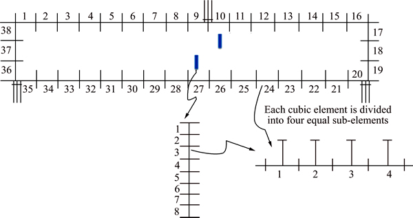
Fig. 6 discretization of cracking boundaries for double cracked beam specimen
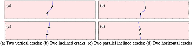
Fig. 7 Numerical simulation of crack propagation paths and cracks coalescence for double cracked beam specimens under three-point bending:
 (12)
(12)
The normalized mode I and mode II SIFs are simplified as
 (13)
(13)
The normalized analytical values of  and
and  can be estimated from eq.(12) as 0.884 and 0.451, respectively.
The inclined edge crack problem (Fig. 8) has been numerically solved by the proposed approach and the results are compared with the analytical results.
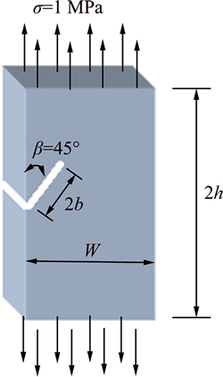
Fig. 8 a rectangular specimen containing inclined edge notch with W/h =1, b/W=0.3, W=50 mm
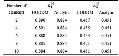
Table 2 shows the effect of the number of elements which show the accuracy of the proposed method. The table illustrates the high accuracy of the proposed boundary element method by using a relatively small number of elements (about 8 cubic displacement discontinuity elements containing 32 nodes).
Table 2 analytical and numerical values of mode I and mode II stress intensity factors  and
and  for rectangular specimen containing inclined edge notch using different number of elements along crack (L/b=0.1)
The crack propagation process in rock samples has been studied by several researches using the edge cracked problem under shear loading.
LEE and JEON [8] have numerically (using a discrete element method (DEM) code) presented the solution for the problem shown schematically in Fig. 9 considering a rock-like specimen with length L=120 mm and width w=60 mm (L/w=2) containing a center slant crack with a half-length, b=10 mm and inclination angle, ��.

Fig. 9 A schematic view of a propagated center slant crack (with two wing cracks) in a rock specimen under uniaxial compression
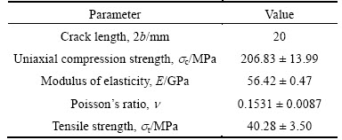
LEE and JEON [8] have numerically investigated the crack propagation patterns for different flaw inclination angles, ��=30��, 45��, 60��, and 90��. They have used PFC2D code (a 2-D discrete element code) to conduct a number of numerical simulations. Table 3 shows the mechanical properties of rock specimens used in their simulations.
Figures 10 demonstrates the PFC2D simulations of the crack propagating paths in single-cracked specimens with variable crack inclination angles, ��=30��, 45��, 60��, and 90��, respectively [8].
Table 3 Mechanical properties of rock specimen [8]
In this work, the same problem is solved numerically with the proposed indirect boundary element method (displacement discontinuity method). The numerical results obtained by the boundary element simulation of pre-cracked specimens are shown in Fig. 11. Comparing Fig. 10 and Fig. 11 illustrate that the crack propagation paths shown in Fig. 11 are in good agreement with the numerical results given by LEE and JEON [8] in Fig. 10.
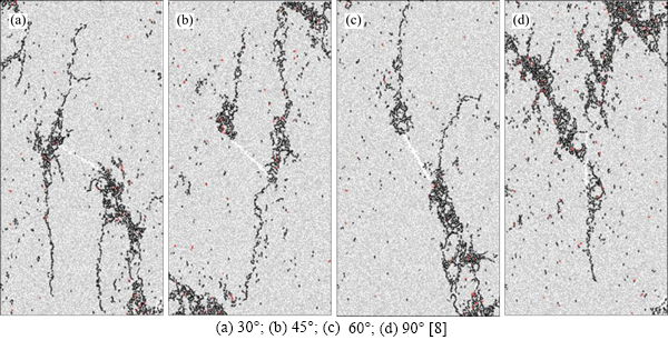
Fig. 10 PFC2D simulation of propagating paths in single-cracked specimens with variable crack inclination angles:
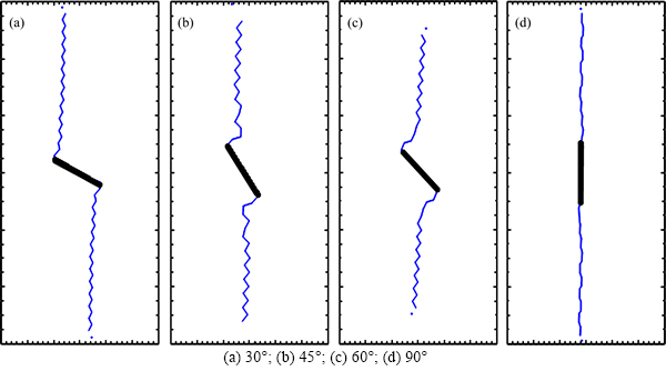
Fig. 11 Boundary element simulation of crack propagation process in single-cracked specimens with different crack inclination angles:
Comparing these numerical results with those obtained by PFC2D code (given in Figs. 10) demonstrates the accuracy and validity of the boundary element results. It should be noted that boundary element code (where applicable) is much faster as this method essentially reduces one dimension of the problem and alternatively reduces the mesh size sharply and makes the discretization of the problem simpler and quicker.
5 Conclusions
1) The mechanism of crack propagation in brittle solids under three-point bending has been studied by experimental and numerical studies. As this mechanism is a complicated process, a further research may be devoted to investigate the crack propagation, cracks coalescence and final breakage paths of a rock bridge area under three-point bending condition.
2) Three-point bending tests are conducted on concrete beam specimens (each specimen contains two internal cracks). Various types of the specially prepared double cracked beam (DCB) specimens are tested to study the crack propagation process of the pre-cracked brittle solids. These specimens (with different crack positions) are tested in the laboratory.
3) A modified higher order displacement discontinuity method, which is a category of the broad boundary element method, is especially arranged to simulate the mechanism of crack propagation and cracks coalescence in the double cracked beam (DCB) specimens. The linear elastic fracture mechanics (LEFM) theory based on mode I and mode II stress intensity factors (SIFs) is used in the numerical simulation. The effects of crack positions on the fracturing path in the bridge areas of the double cracked beam specimens) have been modeled. It has been shown that the fracturing of double cracked specimens occurs mainly by the propagation of wing cracks emanating from the tips of the two internal cracks. The numerical results well illustrate the cracks propagation paths produced by the coalescence phenomenon of the internal cracks.
4) Effects of the number of elements on the values of the normalized mode I and mode II stress intensity factors are investigated by the proposed boundary element method. The proposed boundary element method gives very accurate results by using a relatively small number of elements. it has been shown that there is a good agreement between the corresponding numerical and experimental results.
References
[1] ZENG G, YANG X, YINA A, BAI F. Simulation of damage evolution and crack propagation in three-point bending pre-cracked asphalt mixture beam [J]. Construction and Building Materials, 2014, 55: 323-332.
[2] WANG T, DAI J G, ZHENG J J. Multi-angle truss model for predicting the shear deformation of RC beams with low span-effective depth ratios [J]. Engineering Structures, 2015, 91: 85-95.
[3] OZCEBE G. Minimum flexural reinforcement for T-beams made of higher strength concrete [J]. Canadian Journal of Civil Engineering, 2011, 26: 525-534.
[4] RUIZ G, CARMONA R J. Experimental study on the influence of the shape of the cross-section and the rebar arrangement on the fracture of LRC beams [J]. Materials and Structures, 2006a, 39: 343-352.
[5] RUIZ G, CARMONA R J, CENDON D A. Propagation of a cohesive crack through adherent reinforcement layers [J]. Computer Methods in Applied Mechanics and Engineering, 2006b, 195: 7237-7248.
[6] JAEIRO R P, EINSTEIN H H. Experimental study of the cracking behavior of specimens containing inclusions (under uniaxial compression) [J]. Int J Fract, 2010, 164: 83-102.
[7] YANG S Q. Crack coalescence behavior of brittle sandstone samples containing two coplanar fissures in the process of deformation breakage [J]. Engin Fract Mech, 2011, 78: 3059-3081.
[8] LEE H, JEON S. An experimental and numerical study of fracture coalescence in pre-cracked specimens under uniaxial compression [J]. Int J Solids and Structures, 2011, 48: 979-999.
[9] AMEEN M, RAGHU PARASAD B K, GOPALAKRISHNAN A R. Modeling of concrete cracking��A hybrid technique of using displacement discontinuity element method and direct boundary element method [J]. Engineering Analysis with Boundary Elements, 2011, 35: 1054-1059.
[10] XIA K, ZHENG H, WANG Y X. Determination of dynamic rock mode-I fracture parameters using cracked chevron notched semi�Ccircular bend specimen [J]. Eng Fract Mech, 2011, 78: 2633-2644.
[11] AYATOLLAHI M R, SISTANINIA M. Mode II fracture study of rocks using Brazilian disk specimens [J]. Int J Rock Mech Min Sci, 2011, 48: 819-826.
[12] WANG Q Z, FENG F, NI M, GOU X P. Measurement of mode I and mode II rock dynamic fracture toughness with cracked straight through flattened Brazilian disc impacted by split Hopkinson pressure bar [J]. Eng Fract Mech, 2011, 78: 2455-2469.
[13] TAVARAL L, MANTIC V, GRACIANI E, PARIS F. BEM analysis of crack onset and propagation along fiber�Cmatrix interface under transverse tension using a linear elastic-brittle interface model [J]. Engineering Analysis with Boundary Elements, 2011, 35: 2207-2221.
[14] PU Cheng-zhi, CAO Ping. Breakage characteristics and its influencing factors of rock-like material with multi-fissures under uniaxial compression [J]. Transactions of Nonferrous Metals Society of China, 2012, 22: 185-191.
[15] TANG Chun-an, YANG yue-feng. Crack branching mechanism of rock-like quasi-brittle materials under dynamic stress [J]. Journal of Central South University, 2012, 19: 3273-3284.
[16] ZHAO yan-lin, CAO Ping, WANG Wei-jun, WAN Wen, CHEN Rui. Wing crack model subjected to high hydraulic pressure and far field stresses and its numerical simulation [J]. Journal Central South University, 2012, 19: 578-585.
[17] LEONEL E D, CHATEAUNEUF A, VENTURINI W S. Probabilistic crack growth analyses using a boundary element model: Applications in linear elastic fracture and fatigue problems [J]. Engineering Analysis with Boundary Elements, 2012, 36: 944-959.
[18] LANCASTER I M, KHALID H A, KOUGIOUMTZOGLOU I A. Extended FEM modelling of crack propagation using the semi-circular bending test [J]. Construction and Building Materials, 2013, 48: 270-277.
[19] YOSHIHARA H. Initiation and propagation fracture toughness of solid wood under the mixed Mode I/II condition examined by mixed-mode bending test [J]. Engin Fract Mech, 2013, 104: 1-15.
[20] JIANG Z, WAN S, ZHONG Z, LI M, SHEN K. Determination of mode-I fracture toughness and non-uniformity for GFRP double cantilever beam specimens with an adhesive layer [J]. Engin Fract Mech, 2014, 128: 139-156.
[21] NOEL M, SOUDKI K. Estimation of the crack width and deformation of FRP-reinforced concrete flexural members with and without transverse shear reinforcement [J]. Engineering Structures, 2014, 59: 393-398.
[22] HAERI H, SHAHRIAR K, MARJI M F, MOAREFVAND P. On the cracks coalescence mechanism and cracks propagation paths in rock-like specimens containing pre-existing random cracks under compression [J]. Journal of Central South University, 2014, 21(6): 2404-2414.
[23] SHEN B, STEPHANESSON O. Modification of the G-criterion for crack propagation subjected to compression [J]. Engin Fract Mech, 1994, 47: 177-189.
[24] SCOTT M A, SIMPSON R N, EVANS J A, LIPTON S, BORDAS S P, HUGHES T J, SEDERBERG T W. Isogeometric boundary element analysis using unstructured Tsplines [J]. Comput Meth Appl Mech Eng, 2013, 254: 197-221.
[25] MARJI M F. On the use of power series solution method in the crack analysis of brittle materials by indirect boundary element method [J]. Engin Fract Mech, 2013, 98: 365-382.
[26] OLIVEIRA H L, LEONEL E D. An alternative BEM formulation, based on dipoles of stresses and tangent operator technique, applied to cohesive crack growth modeling [J]. Engineering Analysis with Boundary Elements, 2014, 41: 74-82.
[27] LEI J, WANG Y S, HUANG Y, YANG Q, ZHANG C. Dynamic crack propagation in matrix involving inclusions by a time-domain BEM [J]. Engineering Analysis with Boundary Elements, 2012, 36: 651-657.
[28] PARK C H, BOBET A. Crack initiation, propagation and coalescence from frictional flaws in uniaxial compression [J]. Engin Fract Mech, 2010, 77: 2727-2748.
[29] LI H, WONG L N Y. Influence of flaw inclination angle and loading condition on crack initiation and propagation [J]. Int J Solids and Structures, 2012, 49: 2482-2499.
[30] MARJI M F. On the use of power series solution method in the crack analysis of brittle materials by indirect boundary element method [J]. Engin Fract Mech, 2013, 98: 365-382.
[31] GHAZVINIAN A, SARFARAZI V, SCHUBERT W, BLUMEL M. A study of the failure mechanism of planar non-persistent open joints using PFC2D [J]. Rock Mech Rock Eng, 2011, 45: 677-693.
[32] SARFARAZI V, GHAZVINIAN A, SCHUBERT W, BLUMEL M, NEJATI H R. Numerical simulation of the process of fracture of echelon rock joints [J]. Rock Mech Rock Eng, 2013, doi:10.1007/s00603-013-0450-3.
[33] CROUCH S L. Analysis of stresses and displacements around underground excavations: an application of the displacement discontinuity method [R]. Minneapolis, Minnesota: University of Minnesota Geomechanics, 1967.
[34] CROUCH S L, STARFIELD A M. Boundary element methods in solid mechanics [M]. London: Allen and Unwin, 1983.
[35] BOWIE L. Solutions of plane crack problems by mapping techniques [S]. Mech Fract, 1973.
[36] ERDOGAN F, SIH G C. On the crack extension in plates under loading and transverse shear [J]. Fluids Eng, 1963, 85: 519-527.
(Edited by YANG Hua)
Received date: 2015-03-18; Accepted date: 2015-06-13
Corresponding author: Hadi Haeri, Assistant Professor; Tel: +98-9128949001; E-mail: hadihaeri@ymail.com; haerihadi@gmail.com

