Trans. Nonferrous Met. Soc. China 28(2018) 2107-2113
Crack initiation rate of brittle rock under thermal-hydro-mechanical coupling condition
Zhuo LI1, Qiu-hua RAO1, Peng LI2, Wei YI1
1. School of Civil Engineering, Central South University, Changsha 410075, China;
2. PowerChina Zhongnan Engineering Corporation Limited, Changsha 410014, China
Received 18 August 2017; accepted 4 April 2018
Abstract: A calculation formula of thermal-hydro-mechanical (THM) coupling crack initiation rate for brittle rock was derived based on the energy conservation law. The self-designed THM coupling fracture test with conductive adhesive electrical measurement method was applied to measuring the THM coupling crack propagation rate of brittle rock continuously. Research results show that both calculation and test results of crack initiation rate increased with increase of the temperature and the hydraulic pressure. They are almost in good agreement, which can prove validity of the calculation formula of THM coupling crack initiation rate.
Key words: crack initiation rate; thermal-hydro-mechanical coupling test; conductive adhesive electrical method; fracture mechanism; brittle rock
1 Introduction
In deep rock engineering, such as deep mining, geothermal exploitation and underground nuclear waste processing, rock is usually subjected to thermal-hydro- mechanical (THM) coupling condition. Its pre-existing cracks would initiate and propagate and result in failure of rock. Determination of crack initiation rate becomes an important precondition for lifetime prediction and crack arresting control.
Currently, crack propagation rate is mainly calculated by double torsion test (DT) under displacement control based on relationship between the specimen flexibility and crack propagation length or, between the specimen flexibility and its energy release [1-5]. This method can be applicable for Mode I (tensile) fracture of rock material under simple loading condition but not for Mode I or Mode II fracture under THM coupling condition. In experimental study, the crack initiation rate could be measured by optical, acoustic and electric methods. For example, high-speed digital photography was used to determine the crack propagation rate [6-9], by photographing the surface of the specimen directly. However, it is not suitable for complicated loading conditions (such as THM). The acoustic method is applied for qualitative rather than quantitative description of the crack propagation rate [10,11]. The electrical method is widely used to measure the crack propagation rate by strain gauge discontinuously [12-14]. Recently, our research group has designed a new conductive adhesive electrical method to measure the crack propagation rate continuously under TM and THM coupling conditions [15,16]. It needs to further investigate a better calculation method for crack initiation rate under THM coupling condition.
In this study, the energy conservation law was used to deduce calculation formula of THM coupling crack initiation rate for brittle rock. Self-designed THM coupling fracture test with conductive adhesive electrical measurement method was successfully applied to measuring the THM coupling crack propagation rate continuously and verify its calculation formula. Research findings would provide theoretical basis for lifetime prediction and crack-arrest control of brittle rock under THM coupling condition.
2 Formula derivation of crack initiation rate under THM coupling condition
2.1 Calculation model
Figure 1 shows a standard rock specimen (D=50 mm and L=100 mm) of an inclined penetrating crack (2a=30 mm and ��=45��), which is subjected to temperature T, hydraulic pressure pH on the crack surface, axial pressure pL and confining pressure pM, i.e., THM coupling load.
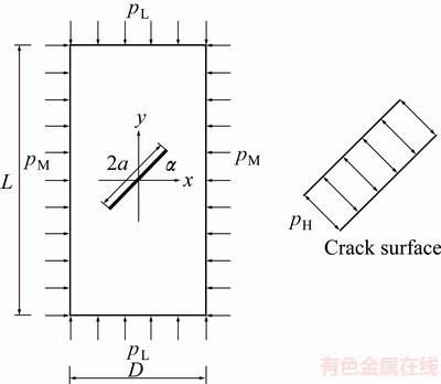
Fig. 1 Rock specimen under THM coupling condition
2.2 Calculation formula
Figure 2 illustrates a typical stress-strain curve of the pre-crack rock specimen under THM coupling load. It is usually classified into four stages: non-linear compaction (OA), elastic deformation (AB), damage (BC) and failure (CD). In the damage stage (BC), crack propagation is dominant regardless of small plastic deformation for the brittle rock specimen.
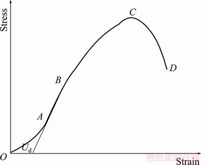
Fig. 2 Schematic diagram of stress-strain curve
Under THM coupling condition, total work of external load (WTHM) consists of heat energy (WT), hydraulic work (WH), axial compression work (WL) and confining pressure work (WM), i.e.,

 (1)
(1)
where ��T is the coefficient of thermal expansion, E is the elastic modulus, T is the temperature, lH, lL and lM correspond to displacements caused by hydraulic pressure, axial pressure and confining pressure, respectively.
In special case, when the specific temperature is constant during process of THM loading condition, Eq. (1) becomes
 (2)
(2)
According to energy method, the total work of external load (WTHM) is completely exchanged into storage energy of the rock specimen, including dissipation energy of non-linear compaction (Ud), elastic strain energy (Ue) [17] and fracture surface energy �� [18] as follows:
 (3)
(3)
where ��B is the critical strain at crack initiation point B, ��1 is the principal stress, ��3 is the confining stress, V is the volume of rock specimen, G is the energy release rate, A is the crack area, a and b are crack length and crack width, respectively.
Since b is almost unchanged at the initial stage of BC, it can be regarded as a constant and obtained by geometrical relation of the pre-crack rock specimen (Fig. 3).
 (4)
(4)
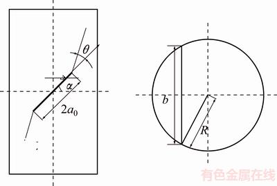
Fig. 3 Determination of crack width at crack tip
3 Determination of crack initiation rate
3.1 THM test
THM test was used to determine the energy release rate G and dissipation energy of non-linear compaction stage Ud in order to calculate the crack initiation rate vi. Rock material adopted in this study is red sandstone. Tables 1 and 2 list its main mechanical parameters at room temperature (including elastic modulus E, Poisson ratio v, tensile strength ��t, compressive strength ��c, cohension C and internal friction angle ��) and elastic modulus E and fracture toughness (KIC and KIIC) at different temperatures, which are obtained by testing standard methods of International Society for Rock Mechanics (ISRM) [19].
Table 1 Rock mechanical parameters at room temperature
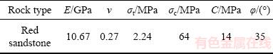
Table 2 Elastic modulus and fracture toughness at different temperatures
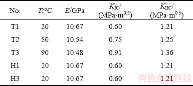
Figure 4 shows a standard cylinder specimen of red sandstone with an inclined penetrating crack. It has the same size as the calculation model (Fig. 1). A hole column must be drilled from the bottom to the crack center in order to apply hydraulic pressure on the crack surface (Fig. 5).

Fig. 4 Red sandstone specimen
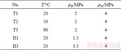
Figure 6 shows the THM coupling test system, including MTS rigid testing machine with triaxial chamber, hydraulic pressure and confining pressure loading systems. Isolation membrane must be set in the triaxial chamber in order to avoid mixture of water and oil. Table 3 lists the THM coupling test condition, where T<100 ��C for preventing water from vapor and pH M for preventing mixture of water and oil. The rock specimen was heated to the specified temperature (T) by a heating furnace firstly, and then wrapped with an isolation membrane (for preventing mixture of water and oil) and put into the triaxial chamber rapidly. The water (heated to the same specified temperature) was injected into the hydraulic pressure system to apply hydraulic pressure pH on the crack surface by the hole column (from bottom to crack center). Under a constant confining pressure pM, the rock specimen was loaded axially until failure. During the test, axial stress-strain curve and voltage-time curve of the conductive adhesives were measured continuously and thus the crack initiation rate could be obtained.

Fig. 5 Hole column in specimen
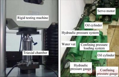
Fig. 6 THM coupling test system
Table 3 THM coupling test condition
3.2 Energy release rate
Figure 7 shows the THM coupling stress-strain curves of the rock specimens under different temperatures and hydraulic pressures. It is shown that the higher the temperature is, the lower the peak strength is. When the hydraulic pressure applied on the crack surface is increased, the crack initiation occurs more easily and thus the peak strength is decreased.

Fig. 7 THM coupling stress-strain curves of rock specimens (pM=4 MPa)
Figure 8 shows fracture trajectories of the rock specimens at different temperatures and hydraulic pressures. The crack initiation mechanism can be determined by the new fracture criterion of maximum stress intensity factor ratio proposed by our research group [20,21]. The tension fracture (Mode I) occurs under high temperature and hydraulic pressure (specimens T3 and H3), and shear fracture (Mode II) occurs under low temperature and hydraulic pressure (specimens T1, T2 and H1). Table 4 lists the energy release rate G calculated by the relation between K and E (Eq. (5)).
G=K2/E (5)
3.3 Dissipation energy of non-linear compaction stage
As shown in Fig. 2 and Eq. (3), Ud is unchanged before and after the crack initiation and propagation. It can be calculated by the non-linear compaction and elastic stage of the stress-strain curve.
Ud=WTHM-Ue (��<��B) (6)
where WTHM and Ue are determined by Eqs. (2) and (3).
Table 5 lists calculation results of WTHM, Ue and Ud according to the stress-strain curves.

Fig. 8 Fracture trajectories under different THM conditions
Table 4 Energy release rate
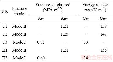
Table 5 Energy at crack initiation point

3.4 Calculation results of crack initiation rate
When the crack is initiated, vi can be calculated by Eq. (3).
 (�šܦ�B) (7)
where WTHM and Ue are determined by Eqs. (2) and (3) based on the THM coupling stress-strain curve (Fig. 7), and Ud is listed in Table 5.
Figures 9 and 10 show the curve of fracture surface energy �� (��=WTHM-Ue-Ud) varying with time t at different T and pH. The crack initiation rate can be calculated by slope of the ��-t curve, as listed in Table 6. Taking specimen T1 as an example, the slope of fracture surface energy �� (equal to 0.0081 J/m) can be obtained by fitting at the crack initiation point (228 s).
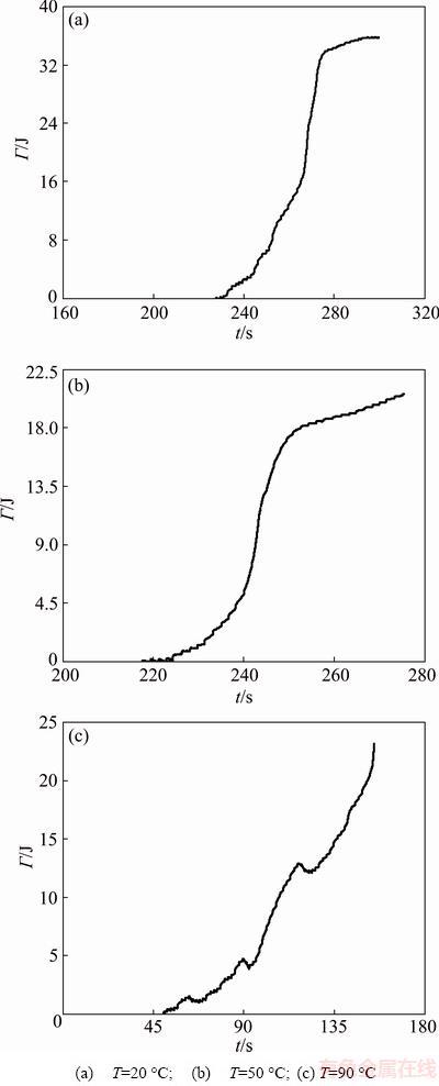
Fig. 9 Fracture surface energy varying with time at different temperatures (pH=2 MPa)

Fig. 10 Fracture surface energy varying with time at different hydraulic pressures (T=20 ��C)
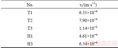
Table 6 Calculation results of crack initiation rate vi
4 Real-time measurement of crack propagation rate
4.1 Conductive adhesive electrical method
Figure 11 shows self-designed conductive adhesive electrical method for measuring the crack propagation rate continuously. The rock specimen was coated with a layer of conductive adhesive (2b=10 mm in width and d=0.1 mm in thickness) from two crack tips along two predicted directions of the crack initiation and propagation. Each conductive adhesive (R1, R2) was connected by two wires in an electric circuitin (Fig. 12) in order to measure its voltage (U1, U2) and obtain its resistance (R1, R2) in the process of the crack initiation and propagation as follows [16]:
 (8)
(8)
where �� is the electrical resistivity of conductive adhesive, a0 is the initial effective length and ai is crack propagation length of conductive adhesive.
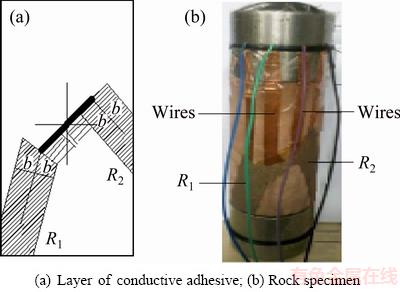
Fig. 11 Conductive adhesive electrical method for measurement of crack initiation rate

Fig. 12 Measurement of conductive adhesive voltage
Therefore, the crack initiation rate can be determined by a calibration formula of the conductive adhesive resistance and the crack length [16].
 (9)
(9)
where U0 is the constant voltage and Ui(t) is the voltage in real time of conductive adhesive, measured by THM coupling fracture test, and R0i is the fixed resistance.
4.2 Test results of crack initiation rate
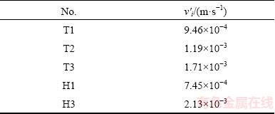
Figure 13 shows the tested curve of the conductive adhesive voltage varying with time (T1 as example). According to Eq. (9), crack initiation rate can be obtained as listed in Table 7.
 (10)
(10)
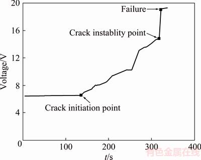
Fig. 13 Voltage of conductive adhesive varying with time (H1) [16]
Table 7 Test results (v��i) of crack initiation rate
4.3 Comparison of calculation and test results
It is seen from Tables 6 and 7 that the crack initiation rate is increased as the temperature is increased. Since the red sandstone is mainly composed of crystal and clay cement, the higher the temperature, the faster the reaction velocity of clay cement and water, and the lower the strength of clay cement and crystal. Similarly, the crack initiation rate is increased as the hydraulic pressure is increased because the lager hydraulic pressure on crack surface is easier to promote crack propagation.
There appear small errors between calculation and test results of the crack initiation rate. That is because the actual Mode I or Mode II fracture toughness (KIC or KIIC) of rock under THM coupling condition is lower than that under single loading condition (in air). For red sandstone, its permeability is very high and its fracture toughness in water is decreased by 30%-60%. Therefore, the test results of the crack initiation rate are larger than the calculation results.
5 Conclusions
1) Calculation formula of the crack initiation rate of brittle rock under THM coupling load can be deduced based on the energy conservation theory.
2) Self-designed THM coupling fracture test with self-designed conductive adhesive electrical method is successfully adopted to measure the crack initiation rate of rock continuously and efficiently, especially under multi-field coupling load condition.
3) The crack initiation rate is increased as the temperature and hydraulic pressure are increased. The tension (Mode I) fracture occurs more easily in the condition of high temperature and hydraulic pressure.
4) Test results of crack initiation rate are almost in agreement with the calculation results, which could verify the validity of the calculation formula of the crack initiation rate.
References
[1] EVANS A G. A method for evaluating the time-dependent failure characteristics of brittle materials��and its application to polycrystalline alumina [J]. Journal of Materials Science, 1972, 7(10): 1137-1146.
[2] LI Jiang-teng, CAO Ping, YUAN Hai-ping. Testing study of subcritical crack growth velocity and fracture toughness of marble [J]. International Journal of Coal Science & Technology, 2005, 11(1): 23-25.
[3] NARA Y, KANEKO K. Sub-critical crack growth in anisotropic rock [J]. International Journal of Rock Mechanics and Mining Sciences, 2006, 43(3): 437-453.
[4] LIU T, CAO P. Testing study of subcritical crack growth mechanism during water rock interaction [J]. Geotechnical and Geological Engineering, 2016, 34(4): 923-929.
[5] NARA Y, KASHIWAYA K, NISHIDA Y, LI T. Influence of surrounding environment on subcritical crack growth in marble [J]. Tectonophysics, 2017, 706: 116-128.
[6] LEE D, TIPPUR H, KIRUGULIGE M. Experimental study of dynamic crack growth in unidirectional graphite/epoxy using digital image correlation method and high-speed photography [J]. Journal of Composite Materials, 2009, 43(19): 2081-2108.
[7] PIERRON F, SUTTON M A, TIWARI V. Ultra high speed DIC and virtual fields method analysis of a three point bending impact test on an aluminium bar [J]. Experimental Mechanics, 2011, 51(4): 537-563.
[8] AVACHAT S, ZHOU M. High-speed digital imaging and computational modeling of dynamic failure in composite structures subjected to underwater impulsive loads [J]. International Journal of Impact Engineering, 2015, 77: 147-165.
[9] WANG Meng, ZHU Zhe-ming, WANG Xiong. The growth of mixed-mode I/II crack under impacting loads [J]. Chinese Journal of Rock Mechanics and Engineering, 2016, 35(7): 1323-1332. (in Chinese)
[10] GUO Yan-shuang. The study on experiment, theory and numerical simulation of fracture of three-dimensional flaws in brittle materials [D]. Ji��nan: Shandong University, 2007. (in Chinese)
[11] KIM J S, LEE K S, CHO W J, CHOI H J, CHO G C. A comparative evaluation of stress�Cstrain and acoustic emission methods for quantitative damage assessments of brittle rock [J]. Rock Mechanics and Rock Engineering, 2015, 48(2): 495-508.
[12] BERTRAM A, KALTHOFF J F. Crack propagation toughness of rock for the range of low to very high crack speeds [J]. Key Engineering Materials, 2003, 251-252: 423-430.
[13] HSIEH Chi-tai, KUO Chuh-chih, WANG Chein-lee, CHEN Yue-gau. A study of crack propagation measurement on sandstone with a single inclined flaw under uniaxial compression [J]. Rock and Soil Mechanics, 2011, 32(10): 2917-2921.
[14] ZHANG Q B, ZHAO J. Effect of loading rate on fracture toughness and failure micromechanisms in marble [J]. Engineering Fracture Mechanics, 2013, 102(2): 288-309.
[15] RAO Qiu-hua, XIE Hai-feng, XIE Qiang. In-plane shear (Mode ��) crack sub-critical propagation of rock at high temperature [J]. Journal of Central South University, 2008, 15(s1): 402-405.
[16] LI Peng. Thermal-hydro-mechanical coupling fracture And crack arrest of brittle rock [D]. Central South University, 2014. (in Chinese)
[17] LI Li-yun, WANG Rong-xin, MA Xu, ZHAO Zhan-wen, XU Yan-yan, LU Jing-fang. The energy variety analysis of rock under biaxial compression [J]. Journal of China Coal Society, 2010, 35(12): 2033-2038(6). (in Chinese)
[18] YU Yao-zhong. Fracture mechanics of rock and concrete [M]. Changsha: Central South University of Technology Press, 1991. (in Chinese)
[19] FAIRHURST C E, HUDSON J A. Draft ISRM suggested method for the complete stress-strain curve for intact rock in uniaxial compression [J]. International Journal of Rock Mechanics and Mining Science and Geomechanics Abstracts, 1999, 36(3): 281-289.
[20] RAO Q H, SUN Z Q, STEPHANSSON O, LI C L, STILLBORG B. Shear fracture (Mode II) of brittle rock [J]. International Journal of Rock Mechanics and Mining Sciences, 2003, 40(3): 355-375.
[21] LI Peng, RAO Qiu-hua, LI Zhuo, JING Jing. Thermal-hydro- mechanical coupling stress intensity factor of brittle rock [J]. Transactions of Nonferrous Metals Society of China, 2014, 24(2): 499-508.
������ʯ��-ˮ-����������ٶȼ���
�� 1�����ﻪ1���� ��2���� ��1
1. ���ϴ�ѧ ��ľ����ѧԺ����ɳ 410075��2. �й��罨���� ���Ͽ�������о�Ժ����˾����ɳ 410014
ժ Ҫ�����������غ㶨�ɣ��Ƶ�����ʯ��-ˮ-��(THM)��������º������Լ���������չ�����ٶȵļ��㹫ʽ������������Ƶ�THM ��϶��ѵ��罺�編��ʵʱ�����ز�����������չ�ٶȡ��о���������������ٶ������¶Ⱥ�ˮѹ�����Ӷ����ӡ����������������ǺϽϺã��Ӷ���֤�����Ƶ���THM ��϶��������ٶȼ��㹫ʽ����ȷ�ԡ�
�ؼ��ʣ������ٶȣ���-ˮ-����ϣ����罺��ⷨ�����ѻ�����������ʯ
(Edited by Xiang-qun LI)
Foundation item: Project (51474251) supported by the National Natural Science Foundation of China
Corresponding author: Qiu-hua RAO; Tel: +86-731-88836423; E-mail: raoqh@csu.edu.cn
DOI: 10.1016/S1003-6326(18)64855-1

