J. Cent. South Univ. Technol. (2009) 16: 0954-0960
DOI: 10.1007/s11771-009-0159-3

Forced transverse vibration of rolls for four-high rolling mill
SUN Jian-liang(孙建亮)1,2, PENG Yan(彭 艳)1,2, LIU Hong-min(刘宏民)1,2, JIANG Guang-biao(江光彪)3
(1. State Key Laboratory of Metastable Materials Science and Technology, Yanshan University,
Qinhuangdao 066004, China;
2. Engineering Research Center of Rolling Equipment and Complete Technology of Ministry of Education,
Yanshan University, Qinhuangdao 066004, China;
3. Hot Rolling Mill of Baoshan Iron and Steel Co Ltd, Shanghai 200941, China)
Abstract: In order to investigate the forced transverse vibration of rolls under distributed draught pressure and moment of bending roll force, the forced transverse vibration model of rolls for four-high rolling mill was established. The work roll and backup roll were considered as elastic continuous bodies that were joined by a Winkler elastic layer. According to Euler-Bernoulli beam theory, the forced transverse vibration of rolls was analyzed based on modal superposition method. The forced vibration equations were established when the draught pressure and moment of bending roll force were imposed on the rolls respectively. Numerical modeling was made on 2 030 mm cold tandem rolling mill of Baoshan Iron and Steel Company. Simulation results show that when the work roll is only subjected to different forms of draught pressures, the vibration curves of work roll and backup roll are quadratic curves with amplitudes of 0.3 mm and 45 μm, respectively. When only the moments of bending roll force are imposed on the work roll and backup roll, the vibration curves of work roll and backup roll are quadratic curves, and the amplitudes are 5.0 and 1.6 μm, respectively. The influence of moment of bending roll force on the vibration of work roll is related with the bending roll force.
Key words: four-high mill; forced transverse vibration; rolls; modal superposition method
1 Introduction
The shape quality of strip is required with the development of national economy. The shape of strip is influenced by dynamic characters of rolls directly. In order to improve shape quality of strip, the transverse vibration of rolls should be investigated. At present, there have been few studies on the transverse dynamic characters of rolls.
The research on the transverse vibration of rolls is the extension of that of vertical vibration, that is, the dimension of vertical vibration is expanded along the axial direction of rolls. There have been many studies on the vertical vibration, but there have been few studies on transverse vibration[1-5]. HU et al[6-8] built the vibration model of mill with single freedom and multiple freedoms. The stability was analyzed and the rolling process was simulated. CHEN et al[9-10], and DUAN and ZHONG[11] investigated the vertical vibration of rolling mill mechanics, and analyzed the stability of vertical vibration. In these studies, the work roll and backup roll were simplified to be lumped masses. Under this condition, the thickness of strip and movement of rolls in a plane can be studied. But the dynamic information of rolls along the axial direction of rolls cannot be reflected.
Actually, the work roll and backup roll are continuous bodies[12-13]. In the future, the broad strip mill will be the main form of rolling mill in production, and the width of strip will be wider, the length of rolls will be longer. Under this condition, taking rolls as lumped masses and neglecting information of rolls along axial direction of rolls as before are not sufficient for studying the vibration of rolls and the shape of strip[14-15]. In rolling process, the rolls are worked by external loads, such as distributed draught pressure and moment of bending roll force. So it is necessary to study the forced transverse vibration of rolls.
In this work, the work roll and backup roll were taken as elastic continuous bodies, and the forced transverse vibration of rolls was investigated based on Euler-Bernoulli beam theory. The natural frequency and principal mode of rolls were obtained by free transverse vibration of rolls. The forced vibration equations were obtained when distributed draught pressure and moment of bending roll force were imposed on the rolls[16-18]. Numerical modeling was made on the 2 030 mm mill of Baoshan Iron and Steel Company. The vibration characters of rolls with different loads were investigated.
2 Mathematic model
Fig.1 shows the physical model of four-high mill. The distributed draught pressure is imposed on the work roll; the moment of bending roll force is imposed on the backup roll and work roll. In order to investigate the transverse vibration of rolls, assume that the rolls are homogenously prismatic beams; the work roll and backup roll are connected by a Winkler elastic foundation; and the work roll and backup roll are freely supported beams.
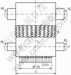
Fig.1 Physical model of rolls
Fig.2 shows the mechanical model of rolls. The work roll and backup roll are coupled by an elastic foundation. Their vibrations affect each other. Considering the universal property of research, the distributed draught pressure and the moment of bending roll force are assumed to be imposed on the work roll and backup roll. Actually, the backup roll is not subjected by distributed draught pressure.
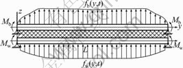
Fig.2 Mechanical model of rolls
On the basis of Euler-Bernoulli model, assuming that the work roll and backup roll are of the same effective material constants, the governing differential equations of transverse vibration of rolls can be expressed by
 (1)
(1)
where zi(y, t) is the transverse deflection of rolls; fi(y, t) is the distributed draught pressure; Ei is the elastic modulus; Ii is the moment of inertia of roll cross section; ρi is the material density; Ai is the area of cross section, K is the elastic coefficient, i=b, w represent the backup roll and work roll respectively.
Assume that Ki=EiIi, mi=ρiAi,  and
and  =?zi/?y(i=b, w), then we have
 (2)
(2)
The work roll and backup roll are assumed to be freely supported beams that are located on the elastic foundation. The boundary and the initial conditions are respectively as follows:
 (3)
(3)

 i=b, w (4)
3 Solution of differential equations of forced vibration
The differential Eq.(2) represents the forced transverse vibration of rolls. In order to solve Eq.(2), the natural frequencies and the corresponding mode shapes should be obtained by solving the free transverse vibration with appropriate boundary conditions firstly. For the free transverse vibration, Eq.(2) becomes
 (5)
(5)
With the governing boundary conditions (3), Eq.(5) can be solved by the Bernoulli-Fourier method. Assuming the solution in the form
 (6)
(6)
where Tin(t) denotes the unknown time function, and sin(kny), kn=nπ/L (n=1, 2, 3, …), is the known mode shape function for simply supported roll.
Substituting Eq.(6) into Eq.(5), and then solving the new equation yields the following frequency equation.
 (7)
(7)
where ωn denotes the natural frequency of rolls, 


 i=b, w.
For each natural frequency, the associated amplitude ratios of vibration modes are given by
 (8)
(8)
Following the above analysis for the free transverse vibration of rolls, particular solutions of differential Eq.(2) can be assumed to be the following form:
 (9)
(9)
 (10)
(10)
where Sin(t)(i=1, 2) denotes the unknown time function corresponding to natural frequency ωin.
Substituting Eqs.(9) and (10) into Eqs.(2) yields
 (11)
(11)
Multiplying both sides of Eq.(11) by eigenfunction Xin, integrating them from 0 to L with respect to y, and following the classical orthogonality condition, we have
 (12)
(12)
From Eq. (12), we have
 (13)
(13)
where H1n(t)= ? sin(kny)dy, H2n(t)=
 ? sin (kny)dy, d1n=-d2n=2(a2n-a1n)-1.
According to Duhamel integral, the solution of Eq.(13) that satisfies the initial conditions is
 (14)
(14)
Hence, the forced transverse vibration of rolls can be written as
 (15)
(15)
4 Analysis of forced transverse vibration in different cases
4.1 Distributed draught pressure
Assuming that the moment of bending roll force is not imposed on the rolls, only the draught pressure is imposed on the work roll. Fig.3 shows the mechanical model of rolls under this condition. For this case, there exist
Mi(t)=0, fw(y, t)≠0, fb(y, t)=0, i=w, b.
where Mi(t) is the moment of bending roll force; and fi(y, t) is the distributed draught pressure.
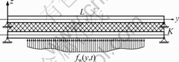
Fig.3 Distributed pressure acting on work roll
Substituting fb(y, t)=0, fw(y, t)≠0 into Eq.(13) leads to
 (16)
(16)
where  and
and  .
.
Assume that the function of distributed draught pressure is
fw(y, t)=fw(y)sin(pt) (17)
where fw(y) denotes the distribution of draught pressure; and p denotes the exciting frequency of load.
Substituting of Eq.(17) into Eq.(14) yields
 (18)
(18)
where  and B is the strip width.
Substituting Eq.(18) into Eq.(15), for this case, the forced transverse vibration of rolls can be written as

(19)
where A1n, A2n, B1n and B2n are the coefficients that can be derived by initial conditions and boundary conditions.
It can be observed that Eq.(19) consists of two parts. The first part containing term sin(pt) represents the steady-state of the forced vibration, while the second part involving term sin(ωint) denotes the free vibration of the system. Assuming that only the steady state response has practical significant, ignoring the free response, the forced transverse vibration of the rolls can be written as
 (20)
(20)
where A1n and A2n denote the steady state vibration amplitudes of the backup roll and work roll, respectively.
4.2 Moment of bending roll force
Assume that the moment of bending roll force is imposed on the rolls, and the draught pressure is not imposed on the rolls. Fig.4 shows the mechanical model of rolls under this condition. In this case, Mi(t)≠0, fi(y, t)=0, i=w, b.
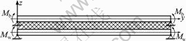
Fig.4 Moments of bending roll force works on rolls
Because moment Mi(t) is not equivalent to general displacement, it should be treated indirectly. Here, when the moment of bending roll force is imposed on the rolls, the forced transverse vibration of rolls is solved based on the method of virtual work. Four kinds of forces are taken into consideration: (1) inertia force, (2) elastic force due to deformation of rolls, (3) interference force moment imposed on each end of rolls, and (4) force due to the elastic foundation.
The expansion equation of deflection curve of backup roll can be written as
 (21)
(21)
where Tbn(t) denotes the unknown time function.
Following the orthogonality of modal function, the virtual work of inertia force can be written as
 (22)
(22)
where δWIn denotes virtual work of inertia force.
It is effective to solve the virtual work of elastic force based on strain energy method. The virtual work of elastic force can be written as
 (23)
(23)
where δWEn denotes virtual work of elastic force.
In order to determine the virtual work of moment, assuming that the force moment rotates  around the action point to produce work , then the virtual work of moment of backup roll can be written as
 (24)
(24)
where  denotes virtual work of the moment, and
  is the first order derivative of Xn(y) with respect to y=y1.
The virtual work of the elastic foundation can be written as

(25)
Summing Eqs.(22)-(25), the result is zero. Then, the transverse vibration equation of backup roll can be derived:
 (26)
(26)
In the same manner, the transverse vibration equation of work roll can be written as
 (27)
(27)
Assume that 
 the moments of bending roll force are
 (28)
(28)
 (29)
(29)
where Mi(s) denotes the moment of bending roll force; Fi(s) denotes the bending roll force; Li denotes the force of arm; and pi denotes the exciting frequency of the moment.
For this case, by solving the differential equations of backup roll and work roll, the forced transverse vibration equations of rolls can be obtained:
 (30)
(30)
 (31)
(31)
where


5 Numerical modeling
The 2 030 mm cold tandem mill of Baoshan Iron and Steel Company was taken as the subject investigated. The transverse vibration of rolls was studied when the distributed draught pressure and the moment of bending roll force were imposed on the rolls. This cold tandem mill includes five four-high cold mills: uncoiler, coiler and other auxiliary equipment. The main parameters of the cold tandem mill are: diameter of work roll, 550-615 mm; length of work roll, 2 030 mm; diameter of backup roll, 1 425-1 550 mm; length of backup roll, 2 030 mm; elastic modulus, Eb=Ew=210 GPa; material density, ρb=ρw=7.8 g/m3; rigidity of elastic foundation, K= 6×10¹⁰ N/m.
The largest diameters of rolls were applied in this work, that was, Db=1 550 mm and Dw=615 mm. The maximum rolling force of the mill is Pmax=30 MN. One specification of the products was taken as subject investigated, and the strip width was B=1 320 mm.
5.1 Distributed draught pressure
The distributed draught pressure was imposed on the work roll. In this case, one has
Mi(t)=0, fb(y, t)=0, fw(y, t)≠0
where fw(y, t)=fw(y)sin(pt).
Under this condition, assume that the forms of draught pressure are uniform, linear and quadratic. Fig.5 shows the distributions of draught pressure.
Fig.6 shows the vibration curves of the work roll
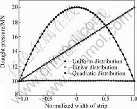
Fig.5 Distributions of draught pressure
corresponding to three different forms of distributed draught pressure. As can be seen, the vibration curves of work roll are similar, which are quadratic curves. When the distribution of draught pressure is uniform and quadratic, the vibration curves are quadratic curves the same and symmetrical to the center of rolls. The amplitude of work roll with quadratic distribution pressure is larger than that with uniform distribution pressure. When the draught pressure is linear distri- bution, the shape of vibration curve is not symmetrical to the center of rolls. The vibration of work roll changes periodically with time and the amplitude is very larger. So this kind of vibration of rolls may lead to shape wave of strip.
Fig.7 shows the vibration curves of backup roll corresponding to three different forms of distributed draught pressures. As can be seen, all the vibration curves of backup roll are quadratic. When the distribution of draught pressure is quadratic, the amplitude of backup roll is the largest. When the
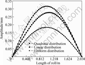
Fig.6 Vibration curves of work roll with three different cases that distribution of draught pressure are uniform, linear and quadratic respectively
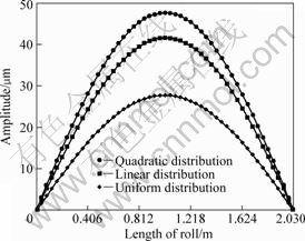
Fig.7 Vibration curves of backup roll with three different cases that distribution of draught pressure are uniform, linear and quadratic respectively
distribution of draught pressure is uniform, the amplitude of backup roll is the smallest. The vibration of work roll changes periodically with time and the vibration of backup roll is small, which has little influence on the work roll.
Comparing Fig.6 and Fig.7, one can see that, when the distributed draught pressure is imposed on the work roll, the vibration curves of work roll fluctuate strenuously than those of the backup roll. The amplitude of work roll is large, which reaches 0.3 mm, and the amplitude of backup roll is small, which reaches 45 μm. The amplitude of work roll is about 7 times as large as that of backup roll. Because work roll is the finishing tool which contacts with the strip directly, the shape quality of the strip is determined by the movement of work roll along the axial direction of rolls.
Fig.8 shows the amplitude―frequency curve of rolls when the distributed draught pressure is imposed on the work roll (n=1). As can be seen, when the frequencies of draught pressure equal the natural frequencies of the rolls, the resonant vibration will happen. Therefore, in order to avoid the accident, the working frequencies should be far away from the natural frequencies. Table 1 shows the natural frequencies of transverse vibration of rolls. Table 2 shows the mode
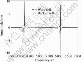
Fig.8 Amplitude―frequency curve of rolls when distributed draught pressure is imposed on work roll(n=1)
Table 1 Natural frequencies of forced transverse vibration
Table 2 Mode coefficients of forced transverse vibration
coefficients of transverse vibration of rolls.
5.2 Moment of bending roll force
The moment of bending roll force was imposed on the work roll and backup roll. For this case, one has
Mi(t)=FiLisin(pit), fi(y, t)=0, i=w, b
where Fb and Fw are the bending roll forces of backup roll and work roll, respectively; Lb and Lw are the bending roll force arms of the backup roll and work roll, respectively; pb and pw are the moment frequencies of backup roll and work roll, respectively.
Fig.9 shows the vibration curves of backup roll and work roll. For this case, assuming that the moments of bending roll force are imposed on the work roll and the backup roll, the moments of bending roll force are equal. As can be seen, the vibration curves of work roll and backup roll are quadratic curves. The amplitude of work roll is larger than that of backup roll. But the amplitudes of work roll and backup roll are all very small, which are 5 and 1.6 μm, respectively. Comparing Fig.6 and Fig.9, one can see that, the transverse vibration of rolls is influenced more strongly by the draught pressure than by the moment of bending roll force.
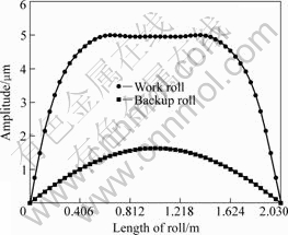
Fig.9 Vibration curves of rolls when moment of bending roll force is imposed
6 Conclusions
(1) In order to investigate the transverse dynamics of rolls, the forced transverse vibration model of rolls for four-high mill is established. The vibration of rolls is investigated based on Euler-Bernoulli beam theory and modal superposition method. The natural frequencies of rolls are determined and the resonance vibration is analyzed.
(2) Numerical modeling is made on the 2 030 mm cold tandem mill of Baoshan Iron and Steel Company. Simulation results show that, whether the distributed draught pressure or the moments of bending roll force are imposed on the rolls, the work roll fluctuates more strenuously than backup roll. The vibration curve of work roll is a high order curve whose amplitude can reach millimeter rank, and the vibration curve of backup roll is a quadratic curve whose amplitude is just micrometer rank. The transverse vibration of work roll can lead to the wave shape of strip. The influence of distributed pressure on the transverse vibration is important.
References
[1] YUN I S, WILSON W R D, EHMANN K F. Chatter in the strip rolling process. Part 1: Dynamic model of rolling[J]. Journal of Manufacturing Science and Engineering, 1998, 120(2): 330-336.
[2] ZHANG Hong, XIONG Shi-bo, WU Bing, LIANG Yi-wei, WANG Ran-feng. Modeling and simulation for vertical vibration of hot rolling mill[J]. China Mechanical Engineering, 2006, 17(23): 2434-2438. (in Chinese)
[3] NIZIOL J, SWIATONIOWSKI A. Numerical analysis of the vertical vibrations of rolling mills and their negative effect on the sheet quality[J]. Journal of Materials Processing Technology, 2005, 162/163: 546-550.
[4] LI Jian-ping, ZHANG Xi-lin, DUAN Ji-an. A new method for monitoring vibration of work roller in rolling mill[J]. Journal of Central South University: Science and Technology, 2004, 35(4): 613-617. (in Chinese)
[5] FAN Xiao-bin, ZANG Yong, WU Di-ping, WANG Yong-tao, LIAO Yi-fan, HUANG Zhi-jian. Vibration problems of CSP hot tandem mill[J]. Chinese Journal of Mechanical Engineering, 2007, 43(8): 198-201. (in Chinese)
[6] HU P H, ZHAO H Y, EHMANN K F. Third-octave-mode chatter in rolling. part 1: Chatter model[J]. Journal of Engineering Manufacture, 2006, 220(8): 1267-1277.
[7] HU P H, ZHAO H Y, EHMANN K F. Third-octave-mode chatter in rolling. Part 2: Stability of a single-stand mill[J]. Journal of Engineering Manufacture, 2006, 220(8): 1279-1292.
[8] HU Pei-hua, ZHAO Hu-yue, EHMANN K F. Third-octave-mode chatter in rolling. Part 3: Stability of a multi-stand mill[J]. Journal of Engineering Manufacture, 2006, 220(8): 1293-1303.
[9] CHEN Yong-hui, LIU Shi-yuan, LIAO Guang-lan. Study on third octave mode chatter on 4-h cold rolling mills[J]. Chinese Journal of Mechanical Engineering, 2003, 39(6): 118-123. (in Chinese)
[10] CHEN Yong-hui, SHI Tie-lin, YANG Shu-zi. Study on parametrically excited nonlinear vibrations on 4-h cold rolling mills[J]. Chinese Journal of Mechanical Engineering, 2003, 39(4): 56-60. (in Chinese)
[11] DUAN Ji-an, ZHONG Jue. Negative damping of rolling interface for rolling chatter[J]. Journal of Central South University of Technology: Natural Science, 2002, 33(2): 401-404. (in Chinese)
[12] ONISZCZUK Z. Free transverse vibration of an elastically connected complex simply supported double-beam system[J]. Journal of Sound and Vibration, 2003, 232(2): 387-403.
[13] ONISZCZUK Z. Forced transverse vibration of an elastically connected complex simply supported double-beam system[J]. Journal of Sound and Vibration, 2003, 264(2): 273-286.
[14] PENG Yan, LIU Hong-min, WANG Dong-cheng. Simulation of type selection for 6-high cold tandem mill based on shape control ability[J]. Journal of Central South University of Technology, 2007, 14(2): 278-284.
[15] PENG Yan, LIU Hong-min. Study on increasing calculated precision and convergence speed of streamline strip element method[J]. Journal of Central South University of Technology, 2004, 11(1): 105-108.
[16] ZHANG Y Q, LU Y, MA G W. Effect of compressive axial load on forced transverse vibration of a double beam system[J]. Internal Journal of Mechanical Sciences, 2008, 50(2): 299-305.
[17] NATSUKI T, NI Q Q, HAYASHI T, ENDO M. Wave propagation in double-walled carbon nanotubes conveying fluid[J]. Journal of Applied Physics, 2008, 103(9): 094312.
[18] DARIO J, ARISTIZABAL O. Static and dynamic stability of uniform beam-columns under generated boundary conditions[J]. Journal of Sound and Vibration, 2007, 307(1/2): 69-88.
(Edited by YANG You-ping)
Foundation item: Project(50875231) supported by the National Natural Science Foundation of China; Project(E2006001038) supported by Great Natural Science Foundation of Hebei Province, China
Received date: 2009-02-25; Accepted date: 2009-05-27
Corresponding Author: PENG Yan, Professor, PhD; Tel: +86-13933691137; E-mail: pengyan@ysu.edu.cn

