���ղ�����AM50Aþ�Ͻ� ˫�س��μ���֯�����ܵ�Ӱ��
��Դ�ڿ����й���ɫ����ѧ��(Ӣ�İ�)2014���2��
�������ߣ����� �� ӭ ������
����ҳ�룺321 - 333
�ؼ��ʣ�AM50Aþ�Ͻ�˫�س��Σ���ѧ���ܣ�����֯
Key words��AM50A magnesium alloy; double control forming; mechanical properties; microstructure
ժ Ҫ��������������ˮƽ����ʵ���о����ղ�����˫�س���AM50Aþ�Ͻ�����ѧ���ܺ�����֯��Ӱ�졣˫�س��εIJ����仯���߱����������������ѹ��������35 ms�������ġ������˫�س��ι��̼Ȱ������ٳ�������־��и�ѹ��ʵ���̡���ѹ����ȣ�˫�س��ι����Ⱦ��кõı��������־��иߵ���ѧ���ܡ�����Ҫ������˫�س��ι�������ϸС�������Ҿ��к���(����û��)����ȱ�ݵ�����֯���¡��뽽ע�¶ȡ�ģ���¶ȺͶ���ѹ����ȣ�ѹ���ٶȶԹ���������ǿ�ȡ�����ǿ�Ⱥ��쳤���и����Ӱ�졣������ѹ���ٶȡ�ģ���¶ȺͶ���ѹ����ȣ���ע�¶ȶԹ�����Ӳ���и����Ӱ�졣��ģ���¶�֮�⣬675 ��C�Ľ�ע�¶ȡ�2.7 m/s��ѹ���ٶȺ�4000 kN�Ķ���ѹ���ǻ����ߵ�����ǿ�ȡ�����ǿ�ȡ��쳤�ʺ�Ӳ�ȵĹ��ղ�������Ҫ�����ߵ�����ǿ�ȡ�����ǿ�ȡ��쳤�ʺ�Ӳ�ȵ�ģ���¶�ƥ��˳��Ϊ��205��195��195�� 225 ��C����ѹ����������Ͽڱ����ܹ��������Ե������ɺ����ơ�˫�س��ι���������Ͽڱ�����ڴ��������ѣ�û������ȱ�ݡ�����������ò�ĶϿڶ�����߹�������ѧ���ܷdz�������
Abstract: Effects of process parameters on microstructure and mechanical properties of the AM50A magnesium alloy components formed by double control forming (DCF) were investigated via a four-factor and four-level orthogonal experiment. The variable curves of DCF showed that the forging procedure was started in the following 35 ms after the injection procedure was completed. It was confirmed that the high-speed filling and high-pressure densifying were combined together in the DCF process. Better surface quality and higher mechanical properties were achieved in the components formed by DCF as compared to die casting (DC) due to the refined and uniform microstructure with a few defects or without defects. Injection speed affected more effectively the yield strength (YS), ultimate tensile strength (UTS) and elongation as compared to pouring temperature, die temperature and forging force. But the pouring temperature had a more significant effect on hardness as compared to injection speed, die temperature and forging force. Pouring temperature of 675 ��C, injection speed of 2.7 m/s and forging force of 4000 kN except for die temperature were the optimal parameters for obtaining the highest YS, UTS, elongation and Vickers hardness. Die temperatures of 205, 195, 195 and 225 ��C were involved in achieving the highest YS, UTS, elongation and Vickers hardness, respectively. Obvious microporosity and microcracks were found on the fracture surface of the components formed by DC, deteriorating the mechanical properties. However, the tensile fracture morphology of the components formed by DCF was characterized by ductile fracture due to a large number of dimples and no defects, which was beneficial for improving the mechanical properties.
Trans. Nonferrous Met. Soc. China 24(2014) 321-333
Ju-fu JIANG1,2, Ying WANG3, Jian-jun QU3
1. School of Materials Science and Engineering, Harbin Institute of Technology, Harbin 150001, China;
2. National Key Laboratory for Precision Hot Processing of Metals, Harbin Institute of Technology, Harbin 150001, China;
3. School of Mechatronics Engineering, Harbin Institute of Technology, Harbin 150001, China
Received 7 January 2013; accepted 13 April 2013
Abstract: Effects of process parameters on microstructure and mechanical properties of the AM50A magnesium alloy components formed by double control forming (DCF) were investigated via a four-factor and four-level orthogonal experiment. The variable curves of DCF showed that the forging procedure was started in the following 35 ms after the injection procedure was completed. It was confirmed that the high-speed filling and high-pressure densifying were combined together in the DCF process. Better surface quality and higher mechanical properties were achieved in the components formed by DCF as compared to die casting (DC) due to the refined and uniform microstructure with a few defects or without defects. Injection speed affected more effectively the yield strength (YS), ultimate tensile strength (UTS) and elongation as compared to pouring temperature, die temperature and forging force. But the pouring temperature had a more significant effect on hardness as compared to injection speed, die temperature and forging force. Pouring temperature of 675 ��C, injection speed of 2.7 m/s and forging force of 4000 kN except for die temperature were the optimal parameters for obtaining the highest YS, UTS, elongation and Vickers hardness. Die temperatures of 205, 195, 195 and 225 ��C were involved in achieving the highest YS, UTS, elongation and Vickers hardness, respectively. Obvious microporosity and microcracks were found on the fracture surface of the components formed by DC, deteriorating the mechanical properties. However, the tensile fracture morphology of the components formed by DCF was characterized by ductile fracture due to a large number of dimples and no defects, which was beneficial for improving the mechanical properties.
Key words: AM50A magnesium alloy; double control forming; mechanical properties; microstructure
1 Introduction
Magnesium alloys present great potential and a number of challenges to successful use in automotive components. Magnesium alloys have received some attention from the automotive industry for the components such as steering wheel frame, instrument panels, oil pump body, seat frames and power train components [1-3] due to the improved fuel efficiency and lowered emission level. The main benefits are the achieved extra-weight reduction, especially when thicker sections are used, which increases the moment of inertia in bending, improving the rigidity, strength, and energy absorption [4]. Magnesium alloys are also used in the bicycles [5], microelectronics [6] and tele- communications [7] industries for the components such as frames, rims, disk drives, DVD chasis and cell phones. Manufacturing processes predominate in improving the mechanical properties of magnesium alloy components, besides the alloy development and heat treatment. High-pressure die-casting (HPDC) is widely used in the processing of magnesium alloy components. Some research work on the HPDC have been conducted by researchers. For example, GUO et al [8] investigated how to determine the interfacial heat transfer coefficient (IHTC) at metal-die interface of HPDC process of AM50 alloy and concluded that the shape of IHTC profiles was different at different steps and the duration for IHTC to maintain a higher value grew with the increase of the step thickness. GERTSMAN et al [9] studied the microstructure and second-phase particles in low- pressure and high-pressure die-cast AM50 magnesium alloy and found that there was a ternary eutectic with the three phases in the Mg-Al-Mn system. HU et al [10] examined the tensile behavior and fracture characteristics of AM50 magnesium alloy and thought that the tensile properties including yield strength (YS), ultimate tensile strength (UTS) and elongation decreased with increasing the section thicknesses of die-cast AM50. Other significant research also focused on creep characteristics of a die-cast AM50 magnesium alloy [11], thermal and structural characteristics of the AM50 magnesium alloy [12], pore size distributions in AM50 magnesium alloy die-castings [13].
However, the existence of casting defects such as microporosity in the microstructure limits the further improvement of mechanical properties of the formed components formed by HPDC. The development of alternative manufacturing processes is essential for the success in applying magnesium alloys for industrial applications due to the effect of microporosity on mechanical properties. Double control forming (DCF) technology with its inherent advantages has been demonstrated capability of minimizing the formation of casting defects in magnesium alloys such as AZ91D and AM60B magnesium alloys [14-16]. Double control forming (DCF) technology combines the die casting and forging in order to form complex components with enhanced properties. However, the effect of the double control forming on the microstructure and mechanical properties of AM50A magnesium alloy was not still reported until now in literatures. Hence, the present research is aiming to investigate the microstructure and mechanical properties of the components of AM50A magnesium alloy formed by DCF and optimize the process parameters affecting the microstructure and mechanical properties.
2 Experimental
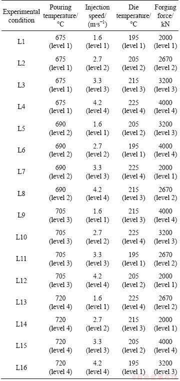
The experiments were performed on an AM50A magnesium alloy containing a composition in mass fraction of 5.1% Al, 0.45% Mn, 0.12%Zn, 0.016% Si, 0.007% Cu, 0.001% Fe, 0.001% Ni and balance Mg. A double control forming (DCF) machine [15] was used to form the components of AM50A magnesium alloy. An electrical furnace with gas shield and quantitative pouring devices was used to melt AM50A magnesium alloy. A mixed gas containing N2 (99.5% in volume fraction) and SF6 (0.5%) was used to prevent the liquid AM50A magnesium alloy from oxidizing or burning. The DCF die was preheated to required temperature by a die preheating equipment in which oil was used as heating medium. A four-factor and four-level orthogonal experiment schedule was designed for the optimization of the process parameters. Four factors involved pouring temperature, injection speed, die temperature and forging force. Four levels were determined according to practical experience. There were 16 experimental conditions in the orthogonal experiment schedule, as depicted in Table 1.
Table 1 Orthogonal experiment schedule of double control forming (DCF) of AM50A magnesium alloy components
A typical complex component was used as the forming target, as shown in Fig. 1. Three same components were formed by DCF under the same experimental conditions. Hence, 48 components were formed by DCF. Similarly, 48 components were also formed by diecasting (DC) in order to make a comparison to DCF. Tensile specimens were machined from the regions 4 to 8, as indicated in Fig.1. Five tensile specimens were machined from each component. Hence 15 tensile specimens under the same experimental condition were tested to determine the mechanical properties including yield strength, ultimate tensile strength, elongation and Vickers hardness.

Fig. 1 Three-dimensional modeling of components showing sampling regions for tensile test and microstructural observation
The average value of 15 specimens�� results was considered the final value of the mechanical properties. All tensile specimens were prepared according to ASTM standard test methods for tension testing of metallic materials, E8M [17]. The tensile test was carried on a universal testing machine (INSTRON 5569) at a crosshead speed of 0.5 mm/min. The Vickers hardness was measured on HV-1000A hardness tester produced in Laizhou Huayin Instrument Co., Ltd., China. The microstructural specimens were machined from the regions 1 to 10. Microstructural specimens were ground by 200, 600, 1000, 1500 and 2000 grit SiC abrasive papers. After these ground samples were polished, etching was carried out in a solution composed of 4.2 g picronitric acid, 10 mL ethanediol, 70 mL ethanol, 10 mL acetic acid and 10 mL distilled water. The microstructure was observed with an Olympus G50 optical microscope (OM) and FEI-quanta 200 scanning electron microscope (SEM) equipped with an energy dispersive X-ray spectrometer (EDX). The grain size of parts formed by DCF and DC was measured by image analysis equipment.
3 Results and discussion
3.1 Comparison of DC and DCF components
Figure 2 shows the variable curves of process parameters during the die casting (DC) and double control forming (DCF). When the oil pressure is 15 MPa, it indicates that the injection pressure is 700 kN [14]. The blue curve illustrates the variation of the oil pressure of forging versus time. When the oil pressure of forging is 7.5 MPa, it means that the forging force of 2000 kN is achieved in the DCF process. As shown in Fig. 2(a), the displacement of plunger increases from 0 to 250 mm in a range from 50 ms to 165 ms and then sharply increases from 250 mm to 500 mm in the following 10 ms. The starting 50 ms is the response time of the system. The oil pressure of injection increases sharply from 1.2 MPa to 15 MPa in a 10 ms range from 165 ms to 175 ms and then kept a constant of 15 MPa. The pressure of 1.2 MPa is the starting pressure of system. The injection speed of piston was divided into two stages. In the first stage, the injection speed increases from 0 to 0.2 m/s in a range of 30 to 80 ms and then keeps a constant of 0.2 m/s until 165 ms. In the second stage, it increases sharply from 0.2 m/s to 3.3 m/s in a 10 ms range from 165 ms to 175 ms. It illustrates that two-speed filling is achieved in the DC and DCF process. In other words, a low speed is to prevent the liquid melt from flashing while the plunger passes the pouring gate and high speed is used to complete the filling process of the melt. The oil pressure of forging always keeps a constant of 1.2 MPa in the DC process, which illustrates that no forging force is performed. Furthermore, it is noted that a same starting time of 165 ms sharp increase of variables is found in the curves during the DC process.
The variation trends of displacement of plunger, oil pressure of injection and injection speeds are the same to those in DC process (Fig. 2(d)). The only difference is the staring time of sharp increase of variables. In the DCF process, the starting time of sharp increase of variables is 175 ms, which is 10 ms later than that in DC process. It is due to the fact that the injection system needs some minor adjustments of process parameters during each injection procedure. It has no effect on the injection procedure. As to oil pressure of forging, an obvious difference is found (Fig. 2(d)). The oil pressure of forging does not keep a constant of 1.2 MPa, but increases sharply from 1.2 MPa to 7.5 MPa in 3 ms. It is illustrated that the forging force (or forging pressure) is performed successfully on the partially solidified slurries of AM50A magnesium alloy. Furthermore, it is the forging force that could effectively remove or reduce the casting defects and refine the microstructure very well [14-16]. As indicated in Fig. 2(d), the forging procedure would be started in 35 ms after the injection procedure is completed. It is confirmed that the high- speed filling of die casting and high-pressure densifying of forging are combined together in the DCF process.

Fig. 2 Curves showing variation of process parameters during die casting (a, b, c) and double control forming (d, e, f)
The components of AM50A magnesium alloy formed by DC and DCF are shown in Fig. 3. As indicated in Fig. 3(a), a flow mark is found in the front of the component formed by DC. It has adverse effect on the surface quality of the component. The components formed by DCF have better surface quality as compared to that formed by DC. No obvious defects are found in the back of the components formed by DC. Good surface quality is also found in the back of the components formed by DCF. However, it is noted that the components formed by DCF have longer overflow than that formed by DC.

Fig. 3 Macrographs of components of AM50A magnesium alloy
It is due to the fact that forging force in the DCF process lead to longer overflow. In other words, when the high-speed filling is completed in the DCF process, the followed forging procedure causes some plastic deformation. Consequently, liquid-solid slurry flows longer into the overflow launders. Hence, a longer overflow is found in the components formed by DCF as compared to that formed by DC, leading to a better filling status.
3.2 Microstructure of DC and DCF components
Figure 4 depicts the optical microstructures of the components formed by DC. A large number of microporosities are found in the microstructure in the region 1 (Fig. 4(a)). A large-sized U-shape microcrack is found in the microstructure in the region 1. Furthermore, a large number of medium-size and small-size microporosities locate below the large-size U-shape microporosity. As indicated in Fig. 4(b), some microporosities are found in the microstructure in the region 4. These microporosities also have adverse effect on the mechanical properties of the components due to accelerating the crack initiation, propagation and fracture.
No obvious defects are found in the microstructure in the regions 5 and 7 (Figs. 4(c) and (e)). Some coarse dendrites are found in the microstructure in the regions 5 and 7. Some fine equiaxed grains, especially in the microstructure in region 5, are also found in the microstructure. The wall in these regions is very thin. Hence, it leads to large supercooling degree in the melt. As a result, a high nucleation rate is achieved, leading to fine equiaxed grains in the thin wall. Two line microcracks are found in the microstructure in region 6 (Fig. 4(d)). As shown in Fig. 4(f), the two line microcracks almost joined together into a long microcrack.
The left two microcracks also almost joined together and formed into a Y-shape microcrack. These microcracks can deteriorate the mechanical properties of the components. It is due to the fact that the microstructure with these microcracks can lead to easier crack initiation, quicker crack propagation and fracture as compared to the microstructure without the microcracks. In general, casting defects such as microcracks and microporosities were easily found in the microstructure of the components formed by DC [14-16]. These casting defects have an adverse effect on the mechanical properties of the components.
Figure 5 shows the optical microstructures of the components formed by DCF. A few small-size microporosities are found in the microstructure in region 1 (Fig. 5(a)). The thickness of region 1 is more than that of other regions, which leads to the final solidification during the whole process. When the forging force can not satisfy the pressure requirement for removing the microporosity due to a large resistance to deformation caused by solidified parts in the castings, a few microporosities will be retained in the formed components. However, the number of the microporosities is reduced sharply as compared to that of die castings, as shown in Fig. 5(a). It is confirmed that the forging force has significant effect on reducing or removing the microporosity in the DCF process.

Fig. 4 Optical microstructures of components formed by DC
Though it is impossible to remove all the microporosities, it to a minimum extent. Intensification pressure significantly reduced the total amount of micro porosities primarily via reduction in the gas porosity [6]. It is very beneficial for improving the mechanical properties of the components formed by DCF. In addition, a large number of fine equiaxed grains except for a few microporosities are found in the microstructure in region 1. Similarly, a large number of fine equiaxed grains are also found in the microstructure in the regions 4-8.
The average sizes of the grains in regions 4-8 were 11, 15, 18, 11 and 13 ��m, respectively. It is confirmed that the grain is very refined. The average size varies in the range of 11 to 18 ��m, which is much smaller than that of die castings. Furthermore, good uniformity is found in the microstructure of the components formed by DCF. The microstructure in regions 4, 6 and 7 is more uniform than that in regions 5 and 8. In general, the size difference in the microstructure of the components formed by DCF is very little. The fine and uniform microstructure without or with a few defects is beneficial for improving the mechanical properties.
The microstructure in regions 2, 3, 9 and 10 of the components formed by DC is illustrated in Fig. 6. No obvious defects are found in the regions 2, 9 and 10 (Figs. 6(a), (c), (d)).

Fig. 5 Optical microstructures of components formed by DCF
Only in the region 3, lots of small-size microporosities were found (Fig. 6(b)). However, the microstructure is not very uniform. As indicated, the ��-Mg17Al12 has an obvious segregation at the grain boundaries (Fig. 6(a)). Furthermore, the obvious size difference was also found in the region 9 (Fig. 6(c)). The coarse grains and fine grains mixed together in the microstructure. The microstructure in the region 10 consisted of a large number of dendrites (Fig. 6(d)).
Compared to diecastings, finer and more uniform equiaxed grains or dendrites are found in the microstructure of the components formed by DCF (Fig. 7). The average grain sizes in regions 2, 3, 9 and 10 are 20, 21, 26 and 32 ��m, respectively. The average sizes are larger than those in regions 4-8. However, it varies in the range of 20 ��m to 32 ��m. There are a few coarse dendritic arms in the microstructure, as indicated in Figs. 7(c) and (d). No defects such as microcracks and microporosities are found in the regions 2, 3, 9 and 10. The black ��-Mg17Al12 intermetallic distributes at the boundary of the grey ��-Mg matrix (Fig. 7(d)). However, some white phases are also found in the microstructure of the components formed by DC and DCF. EDX analysis was performed in the location marked with A in Fig. 7(d) to determine the elements of the phase.
The EDX result is shown in Fig. 8. As indicated in Fig. 8, the phase mainly consists of Mn, Al elements. It is concluded that the phase is Mn5Al8 [9,18,19]. The Mn5Al8 phase is distributed at the boundary or inside ��-Mg. Oxygen peaks which appear in spectra should result from surface oxidation during and after sample preparation [19,20]. The reason for higher composition of Si element than alloy is due to the aggregation of Si element on the boundaries.
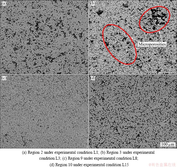
Fig. 6 SEM images of components formed by DC

Fig. 7 SEM images of components formed by DCF

Fig. 8 EDX analysis of microstructure of component formed by DCFs
3.3 Effect of process parameters on mechanical properties of DFC components
Table 2 shows the mechanical properties of the components formed by DC and DCF. As indicated in Table 2, the yield strength (YS), ultimate tensile strength (UTS) and elongation of the components formed by DCF are higher than those of the components formed by DC. The average values of the YS, UTS and elongation of the components formed by DCF are 141.1 MPa, 245.1 MPa and 15.1%, respectively. However, the average values of the YS, UTS and elongation of the components formed by DC are 103.4 MPa, 155 MPa and 5.5%, respectively. The average values of the YS, UTS and elongation of the components formed by DCF increase by 36.5%, 58.1% and 174.5 % respectively as compared to components formed by DC.
Vickers hardness of the components formed by DCF also is enhanced as compared to the components formed by DC. The Vickers hardness of the components formed by DCF is 0.81 GPa, larger than 0.72 GPa of the components formed by DC.
It is illustrated that the mechanical properties of the components formed by DCF, especially elongation are greatly improved as compared to the components formed by DC.
Table 2 Mechanical properties of the AM50A magnesium alloy components formed by double control forming (DCF) and die casting (DC)

The reason for enhanced mechanical properties of the components formed by DCF is due to the fact that the microstructure of the components formed by DCF is refined well and the defects are effectively removed or reduced from the microstructure. Firstly, the densified microstructure without casting defect, such as microcracks and microporosity, is beneficial for improving the mechanical properties of the components formed by DCF [14-16]. Secondly, the refined microstructure caused by high forging pressure [21-23] also leads to the enhancement of the mechanical properties. The YS, UTS and elongation of the components formed by DCF are higher than those of the components formed by HPDC [24-26] and squeeze casting [19,20]. The Vickers hardness of the components formed by DCF is also enhanced as compared to the results reported in Ref. [27].
Tables 3-6 depicts range analysis of mechanical properties of the AM50A magnesium alloy components formed by DCF. As shown in Tables 3-6, injection speed had more effect on YS of the components formed by DCF as compared to forging force, pouring temperature and die temperature. The parameter sequence of affecting the UTS involved injection speed, pouring temperature, die temperature and forging force. The parameter sequence of affecting the E involved injection speed, forging force, pouring temperature and die temperature. Pouring temperature had more effect on Vickers hardness of the components formed by DCF as compared to injection speed, die temperature and forging force. The optimal process parameters for achieving the highest YS are pouring temperature of 675 ��C, injection speed of 2.7 m/s, die temperature of 205 ��C and forging force of 4000 kN. The optimal process parameters for achieving the highest UTS are pouring temperature of 675 ��C, injection speed of 2.7 m/s, die temperature of 195 ��C and forging force of 4000 kN. The optimal process parameters for achieving the highest elongation pouring temperature of 675 ��C, injection speed of 2.7 m/s, die temperature of 195 ��C and forging force of 4000 kN. The optimal process parameters for achieving the highest Vickers hardness are pouring temperature of 675 ��C, injection speed of 2.7 m/s, die temperature of 225 ��C and forging force of 4000 kN.
Table 3 Range analysis of mechanical properties of AM50A magnesium alloy components formed by double control forming according to pouring temperature

Table 4 Range analysis of mechanical properties of AM50A magnesium alloy components formed by double control forming according to injection speed

Table 5 Range analysis of mechanical properties of AM50A magnesium alloy components formed by double control forming according to die temperature

Table 6 Range analysis of mechanical properties of the AM50A magnesium alloy components formed by double control forming according to forging force

Figure 9 depicts the tensile fracture morphologies of the components formed by DCF and DC. As shown in Figs. 9(a)-(d), microporosity and microcrack are found in the fracture surface of the components formed by DC. The same results were also found in Refs. [10,20]. It is illustrated that the mechanical properties of the DC components decrease due to the microcrack and microporosities. When the specimens are loaded, the crack firstly initiates in these defects such as microcrack and microporosities and propagates quickly, leading to quicker crack than those without defects.
The fracture of the component formed by DCF is characterized by ductile fracture morphology due to a large number of dimples (Figs. 9(e) and (f)). Furthermore, no microporosity is found in the fracture microstructure of the components formed by DCF. It is demonstrated that the mechanical properties are effectively improved by DCF technology.
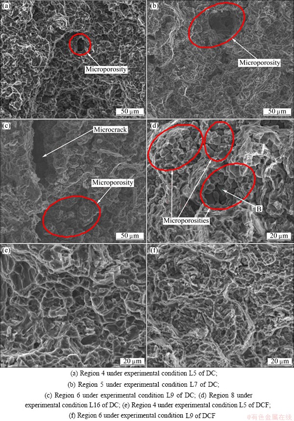
Fig. 9 Tensile fracture morphologies of components formed by DCF and DC
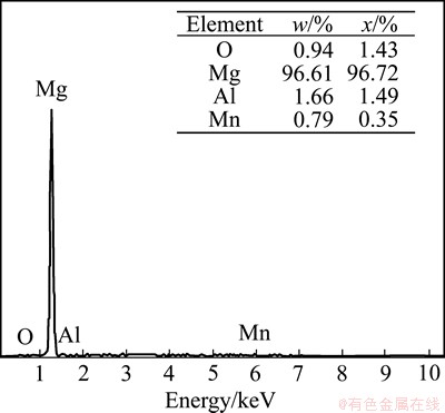
Fig. 10 EDX analysis of fracture of component formed by DC
EDX analysis was carried out on the location marked with B in Fig. 9(d). The EDX analysis results of fracture of the component are shown in Fig. 10. As indicated in Fig. 10, the phase consists mainly of Mg and Al and Mn is very little. It is concluded that the phase is ��-Mg. It is demonstrated that no ��-Mg17Al12 is the boundary between microporosity and ��-Mg. Furthermore, the O element is much less than that in Fig. 8, which illustrates the microporosity is very little. The reason for forming microporosity is due to transformation shrinkage of from liquid phase to solid phase.
4 Conclusions
1) The variable curves during the double control forming (DCF) showed that the forging procedure was started in the following 35 ms after the injection procedure was completed. It is confirmed that the high-speed filling of DC and high-pressure densifying were combined together in the DCF process. Better surface quality was obtained in the components formed by DCF as compared to DC.
2) The mechanical properties of the components formed by DCF were obviously improved as compared to those of the components formed by DC. The reason for enhanced mechanical properties was due to the refined and uniform microstructure with reduced defects or without defects in comparison to the components formed by DC.
4) Injection speed affected more effectively the yield strength (YS), ultimate tensile strength (UTS) and elongation. But the pouring temperature had a more significant effect on hardness as compared to injection speed, die temperature and forging force. Pouring temperature of 675 ��C, injection speed of 2.7 m/s and forging force of 4000 kN except for die temperature were the optimal parameters for obtaining the highest YS, UTS, elongation and Vickers hardness. Die temperature for achieving the highest YS, UTS, elongation and Vickers hardness were 205, 195, 195 and 225 ��C, respectively.
5) Obvious microporosity and microcrack were found in the fracture surface of the components formed by DC, deteriorating the mechanical properties. On the contrary, the tensile fracture morphology of the components formed by DCF was characterized by ductile fracture due to a large number of dimples and no defects, which was beneficial for improving the mechanical properties.
References
[1] FRIEDRICH H, SCHUMANN S. Research for a ��new age of magnesium�� in the automotive industry [J]. Journal of Materials Processing Technology, 2001, 117(3): 276-281.
[2] KULEKCI M K. Magnesium and its alloys applications in automotive industry [J]. International Journal of Advanced Manufacturing Technology, 2008, 39(9): 851-865.
[3] COLE G S, SHERMAN A M. Lightweight materials for automotive applications [J]. Materials Characterization, 1995, 35(1): 3-9.
[4] EASTON M, BEER A, BARNETT M, DAVIES C, DUNLOP G, DURANDET Y, BLACKET S, HILDITCH T, BEGGS P. Magnesium alloy applications in automotive structures [J]. JOM, 2008, 60(11): 57-62.
[5] DEETZ J. The use of wrought magnesium in bicycles [J]. JOM, 2005, 57(5): 50-53.
[6] LEE S G, GOKHALE A M, PATEL G R, EVANS M. Effect of process parameters on porosity distributions in high-pressure die-cast AM50 Mg-alloy [J]. Materials Science and Engineering A, 2006, 427(1): 99-111.
[7] MORDIKE B L, EBERT T. Magnesium: Properties-applications- potential [J].Materials Science and Engineering A, 2001, 302(1): 37-45.
[8] GUO Z P, XIONG S M, LIU B C, LI M, ALLISON J. Determination of the heat transfer coefficient at metal�Cdie interface of high pressure die casting process of AM50 alloy [J]. International Journal of Heat and Mass Transfer, 2008, 51(25): 6032-6038.
[9] GERTSMAN V Y, LI J, XU S, THOMSON J P, SAHOO M. Microstructure and second-phase particles in low- and high-pressure die-cast magnesium alloy AM50 [J]. Metallurgical and Materials Transactions A, 2005, 36(8): 1989-1997.
[10] HU H, ZHOU M, SUN Z Z, LI N Y. Tensile behaviour and fracture characteristics of die cast magnesium alloy AM50 [J]. Journal of Materials Processing Technology, 2008, 201(1): 364-368.
[11] ISHIMATSU N, TERADA Y, SATO T, OHORI K. Creep characteristics of a diecast AM50 magnesium alloy [J]. Metallurgical and Materials Transactions A, 2006, 37(1): 243-248.
[12] KASPRZAK W, SOKOLOWSKI J H, SAHOO M,  L A. Thermal and structural characteristics of the AM50 magnesium alloy [J]. Journal of Achievements in Materials and Manufacturing Engineering, 2008, 28(2): 131-138.
[13]  M. Pore size distributions in AM50 Mg alloy die castings [J]. Materials Science and Engineering A, 2007, 465(1): 287-289.
[14] JIANG J F, WANG Y, LI Y F, SHAN W W, LUO S J. Microstructure and mechanical properties of the motorcycle cylinder body of AM60B Mg alloy formed by combining die casting and forging [J]. Materials and Design, 2012, 37: 202-210.
[15] JIANG J F, WANG Y, LI Y F, SHAN W W, LUO S J. A double control forming technology combining die casting and forging for the production of Mg alloy components with enhanced properties [J]. Journal of Materials Processing Technology, 2012, 212(5): 1991-1199.
[16] JIANG J F, WANG Y, CHEN G, LIU J, LI Y F, LUO S J. Comparison of mechanical properties and microstructure of AZ91D alloy motorcycle wheels formed by die casting and double control forming [J]. Materials and Design, 2012, 40: 541-549.
[17] ASTM standard E8M. Standard test methods for tension testing of metallic materials [S]. West Conshohocken, PA: ASTM International, 2004.
[18] KIELBUS A,  T, CIBIS R. Microstructure of AM50 die casting magnesium alloy [J]. Journal of Achievements in Materials and Manufacturing Engineering, 2006, 18(1-2): 135-138.
[19] ZHANG Q, MASOUMI M, HU H. Influence of applied pressure on tensile behavior and microstructure of squeeze cast Mg alloy AM50 with Ca addition [J]. Journal of Materials Engineering and Performance, 2012, 21(1): 38-46.
[20] ZHOU M, HU H, LI N Y, LO J. Microstructure and tensile properties of squeeze cast magnesium alloy AM50 [J]. Journal of Materials Engineering and Performance, 2005, 14(4): 539-545.
[21] LUO Shou-jing, CHEN Bing-guang, QI Pi-xiang. Liquid forging and squeeze casting technology of metal [M]. Beijing: Chemical Industry Press, 2007. (in Chines)
[22] LI Qiang, LI Zhou-fu, LI Yuan-fa, LUO Shou-jing, GAO Xiao-rong. Forming technique of Mg alloy parts produced by liquid combination process of die casting and forging [J]. Foundry, 2008, 57(9): 895-898. (in Chinese)
[23] KUBOTA K, MABUCHI M, HIGASHI K. Review processing and mechanical properties of fine-grained Mg alloys [J]. Journal of Materials Science, 1999, 34(10): 2255-2262.
[24] SONG J, XIONG S M, LI M, ALLISON J. In situ observation of tensile deformation of high-pressure die-cast specimens of AM50 alloy [J]. Materials Science and Engineering A, 2009, 520(1): 197-201.
[25] CHADHA G, ALLISON J E, JONES W J. The role of microstructure on ductility of die-cast AM50 and AM60 Mg alloys [J]. Metallurgical and Materials Transactions A, 2007, 38(2): 286-297.
[26] WANG R M, ELIEZER A, GUTMAN E M. An investigation on the microstructure of an AM50 magnesium alloy [J]. Materials Science and Engineering A, 2003, 355(1): 201-207.
[27] MA Y L, ZHANG J, YANG M B. Research on microstructure and alloy phases of AM50 magnesium alloy [J]. Journal of Alloys and Compounds, 2009, 470(1): 515-521.
����1,2���� ӭ3��������3
1. ��������ҵ��ѧ ���Ͽ�ѧ�빤��ѧԺ�������� 150001��
2. ��������ҵ��ѧ ���������ȼӹ����Ҽ��ص�ʵ���ң������� 150001��
3. ��������ҵ��ѧ ���繤��ѧԺ�������� 150001
ժ Ҫ��������������ˮƽ����ʵ���о����ղ�����˫�س���AM50Aþ�Ͻ�����ѧ���ܺ�����֯��Ӱ�졣˫�س��εIJ����仯���߱����������������ѹ��������35 ms�������ġ������˫�س��ι��̼Ȱ������ٳ�������־��и�ѹ��ʵ���̡���ѹ����ȣ�˫�س��ι����Ⱦ��кõı��������־��иߵ���ѧ���ܡ�����Ҫ������˫�س��ι�������ϸС�������Ҿ��к���(����û��)����ȱ�ݵ�����֯���¡��뽽ע�¶ȡ�ģ���¶ȺͶ���ѹ����ȣ�ѹ���ٶȶԹ���������ǿ�ȡ�����ǿ�Ⱥ��쳤���и����Ӱ�졣������ѹ���ٶȡ�ģ���¶ȺͶ���ѹ����ȣ���ע�¶ȶԹ�����Ӳ���и����Ӱ�졣��ģ���¶�֮�⣬675 ��C�Ľ�ע�¶ȡ�2.7 m/s��ѹ���ٶȺ�4000 kN�Ķ���ѹ���ǻ����ߵ�����ǿ�ȡ�����ǿ�ȡ��쳤�ʺ�Ӳ�ȵĹ��ղ�������Ҫ�����ߵ�����ǿ�ȡ�����ǿ�ȡ��쳤�ʺ�Ӳ�ȵ�ģ���¶�ƥ��˳��Ϊ��205��195��195�� 225 ��C����ѹ����������Ͽڱ����ܹ��������Ե������ɺ����ơ�˫�س��ι���������Ͽڱ�����ڴ��������ѣ�û������ȱ�ݡ�����������ò�ĶϿڶ�����߹�������ѧ���ܷdz�������
�ؼ��ʣ�AM50Aþ�Ͻ�˫�س��Σ���ѧ���ܣ�����֯
(Edited by Hua YANG)
Foundation item: Project (51075099) supported by the National Natural Science Foundation of China; Project (E201038) supported by the Natural Science Foundation of Heilongjiang Province, China; Project (HIT.NSRIF.2013007) supported by the Fundamental Research Funds for the Central Universities, China; Project (2011RFQXG010) supported by the Harbin City Young Scientists Foundation, China; Project (LBH-T1102) supported by Specially Postdoctoral Science Foundation of Heilongjiang Province, China
Corresponding author: Ju-fu JIANG; Tel: +86-18746013176; E-mail: jiangjufu@hit.edu.cn
DOI: 10.1016/S1003-6326(14)63064-8

