Effect of partial blockage of air duct outlet on performance of OWC device
��Դ�ڿ������ϴ�ѧѧ��(Ӣ�İ�)2012���3��
�������ߣ�M. Rafiuddin Ahmed S. Patel, K. Ram
����ҳ�룺748 - 754
Key words��oscillating water column; wave energy converter; wells turbine; impulse turbine; Savonius rotor
Abstract:
The use of a Savonius rotor as turbine for an oscillating water column (OWC) is demonstrated. The effect of tuning the OWC using turbine duct blockage is also studied for different wave conditions. A horizontal turbine section OWC employing a Savonius rotor was tested by varying the opening of OWC exit (0%, 25%, 50%, 75% and 100%) to study the behavior and performance of the device. The OWC model was tested at water depth of 0.29 m at frequencies of 0.8, 0.9 and 1.0 Hz while the exit openings are varied. The static pressure, dynamic pressure, rotational speed of the Savonius rotor and the coefficient of power are presented as results. The OWC with exit opening of 25% showed greater performance in terms of rotational speed and CP compared to OWC with other exit opening percentages. This proves the ability of the OWC to be tuned by regulating flow in the turbine duct.
J. Cent. South Univ. (2012) 19: 748-754
DOI: 10.1007/s11771-012-1067-5![]()
S. Patel, K. Ram, M. Rafiuddin Ahmed
Renewable Energy Research Group, University of the South Pacific, Suva, Fiji
? Central South University Press and Springer-Verlag Berlin Heidelberg 2012
Abstract: The use of a Savonius rotor as turbine for an oscillating water column (OWC) is demonstrated. The effect of tuning the OWC using turbine duct blockage is also studied for different wave conditions. A horizontal turbine section OWC employing a Savonius rotor was tested by varying the opening of OWC exit (0%, 25%, 50%, 75% and 100%) to study the behavior and performance of the device. The OWC model was tested at water depth of 0.29 m at frequencies of 0.8, 0.9 and 1.0 Hz while the exit openings are varied. The static pressure, dynamic pressure, rotational speed of the Savonius rotor and the coefficient of power are presented as results. The OWC with exit opening of 25% showed greater performance in terms of rotational speed and CP compared to OWC with other exit opening percentages. This proves the ability of the OWC to be tuned by regulating flow in the turbine duct.
Key words: oscillating water column; wave energy converter; wells turbine; impulse turbine; Savonius rotor
1 Introduction
Wave energy is generally considered to provide a clean source of renewable energy and is available in abundance due to the large size of oceans [1]. Wave energy is also more dependable than most energy resources. There are many different types of wave energy converters (WEC) that have been proposed to extract energy from waves, but only few are actually working and are viable for electricity generation [2-4]. The intrinsically oscillating nature and the random distribution of the wave energy resource provide the greatest challenges to designers of wave energy converters [5]. The response of a wave energy device is generally frequency dependent. The peak (resonant) frequency and a range of frequencies that will produce a significant response will depend on the particular device [1]. The most successful and most extensively studied device for extracting energy from sea waves is the oscillating water column (OWC) [6]. The OWC is one of the very few WEC to have reached the stage of full-sized prototype [7]. The OWC comprises of a partly submerged structure open below the water surface, inside which air is trapped above the water free surface [8]. Approaching waves force the internal free surface of the chamber to oscillate; this causes an oscillation of the pressure of the air in the chamber and forces an air flux forwards and backwards through an air turbine, installed in a duct which connects the chamber to the atmosphere [7].
OWC devices are mainly divided into two categories; fixed-type OWC which can be near shore or on-shore and the floating-type OWC which are offshore [9]. The air flow inside an OWC chamber is bi-directional and this provides the uniqueness of the turbine used in an OWC device. According to SETOGUCHI and TAKAO [10], the efficiency of the turbine does not give useful information about the suitable turbine for wave power conversion. The turbine characteristics depend on the efficiency of the air chamber. Several studies have been done to improve the primary capture of the OWC [11-12]. There are several bi-directional turbines including Wells turbine, impulse turbines and Savonius type turbines [13]. The Wells turbine has been the most commonly adopted solution to the energy conversion problem in OWC device [5]. There are several reports which describe the performance of Wells turbine at both the starting and the running characteristics. According to these reports, the Wells turbine has its disadvantages compared to other conventional turbines [14]. The disadvantages are narrow range of flow rates at which it operates at useful efficiencies, poor starting characteristics, high speed operation and consequent noise and high axial thrust [13]. The efficiency of OWC devices equipped with Wells turbines is particularly affected by the flow oscillations basically for two reasons: first, because of the intrinsically unsteady (reciprocating) flow of air displaced by the oscillating water free surface; second, because increasing the air flow rate above a limit and approximately proportional to the rotational speed of the turbine, is known to give rise to a rapid drop in the aerodynamic efficiency and in the power output of the turbine [7]. According to SETOGUCHI et al [14], some researchers have suggested different measures to overcome the drawbacks of a Wells turbine. However, in most cases, the efficiency deteriorates due to an increase in pressure difference between the turbine and a decrease in torque.
SETOGUCHI and TAKAO [10] compared the starting and running characteristics of five different turbines used in wave energy extraction. The tested turbines included the Wells turbine and impulse type turbines. The numerical comparison showed that a better efficiency of around 45% is obtained for impulse turbines with self-pitch controlled guide vanes. MALA et al [15] proposed a twin unidirectional impulse turbine for use in OWC devices. They also carried out numerical simulation and estimated the efficiency of such designs to be around 70%. SANTHAKUMAR et al [13] developed an impulse turbine with self-pitch controlled guide vanes to overcome the drawbacks of the Wells turbine. At present, most designs of OWC use Wells turbines although it has many disadvantages. Apart from its inability to self-start, a Wells turbine displays stalling behavior when flow coefficients exceed a certain value [16-18]. A Wells turbine also requires a high Reynolds number, and hence a larger size, to operate successfully [19].
Of late, there is a growing interest in rectangular OWC chambers and rectangular turbine sections housing Savonius rotors [19-20]. DORRELL et al [19-21] presented a design of a Savonius rotor that was used in an OWC device. They compared multiple chamber arrangements and reported turbine conversion rates of 20.2% for the two bladed Savonius turbines. The Savonius rotor only has a conversion factor up to about 25% at an absolute maximum. Although this value is not large, the advantage lies in the simplicity of design and the ease of construction of these types of turbines for use in remote and developing locations for low-power applications. Savonius type turbine also provides advantage for an OWC device since it allows us to increase the width of OWC parallel to the coast so that a greater amount of energy can be absorbed per device. The chamber of the OWC device can be partitioned so that the Savonius type turbines can be placed in series. Unlike the circular OWC, the width of entry of the capture chamber can be increased in the rectangular ducted OWC without being influenced by the diameter at the turbine section [22]. The Savonius turbine is a much effective solution at low Reynolds numbers, unlike the Wells turbine which requires a high Reynolds number [19].
According to MENET [23], Savonius rotors are known to have miscellaneous advantages. The advantages include high starting torque which enables them not only to run, but also to start at whatever the wind velocity. The components which do energy conversion from mechanical to electrical energy can be placed at the surface, which makes maintenance operations very simplified. Savonius rotors are known to be simple machines which are easy to construct. Also, it cannot be ignored that Savonius rotors have lower efficiencies than horizontal axis turbines for wind applications. However, in the case of OWCs, the simplicity of the Savonius along with its other advantages makes it a competitive option as a power producing turbine. This is a simple and low-cost turbine although the conversion factor is low [24].
ALTAN and ATILGAN [25] proposed the idea of using a curtain arrangement to increase the low aerodynamic performance of the Savonius rotor. A novel approach of incorporating the curtain effect into the chamber of the OWC is taken in this work. The contracting curtains need to be placed on both sides of the turbine due to bi-directional flow. The OWC relies on resonance. If the device is properly tuned to the incoming waves, resonance effect will cause improved oscillating in the chamber and improve airflow through the turbine. It would be ideal that the resonance effect is achieved for all wave conditions. However, this is not the case given that numerous sea states exist. The tuning of the device may be possible by controlling the flow of air in and out of the turbine. In this work, the effect of duct blockage on a cross flow turbine in a rectangular OWC is investigated. The blockage acts as a valve to regulate air entry and exit. This holds promise to dynamically tune an OWC to any sea state as the sea state does not change rapidly. Furthermore, since the free water surface inside the OWC chamber acts like a piston, restricting flow at the atmosphere may result in a higher compression inside the chamber and increasing the ��spring like�� nature of the air in the chamber. The purpose of the present work is to understand how blockage affects chamber pressure and turbine rotational speed in different wave conditions.
2 Experimental method
The experiments on the OWC device were carried out in a Cussons wave channel model P6325 that is 3.5 m long, 0.3 m wide and 0.45 m deep. The wave channel employs a flat wave-maker that is hinged at the base to generate sinusoidal waves. The wave-maker has a width of 0.29 m which is almost a close fit to the width of the wave channel to ensure that two dimensional waves are produced. Controlling the frequency of the wave maker simulates different sea states of various periods. Figure 1 gives a schematic of
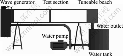
Fig. 1 Schematic diagram of Cussons wave channel
the wave channel.
A Cussons tuneable beach, model P6285, is placed at the other end of the wave channel. The tuneable beach utilizes a series of porous plates to absorb wave energy and minimize reflections of the waves. An OWC model with a horizontal turbine section was constructed out of clear Perspex. The model was built to a scale of 1:100. KOOLA et al [26] used a scale of 1:100 and stated that in Froude scale the model ratio is proportional to the square of the time ratio. The rear wall of the OWC model is inclined at 65�� to reduce wave reflections. The design has a rectangular capture chamber and a turbine section to allow the use of a Savonius type rotor as the turbine. A similar rectangular ducted OWC for Savonius type rotor has been designed and is presented by RAM et al [27]. A nozzle is created on both sides of the turbine section, as shown in Fig. 2.
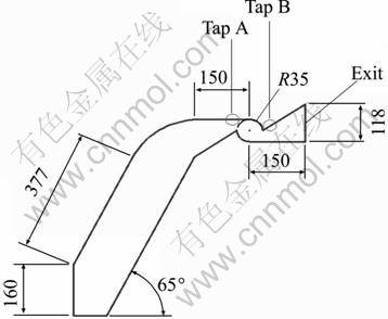
Fig. 2 Schematic diagram of OWC model (Unit: mm)
The nozzle serves two important purposes: one is to increase the velocity of air flowing towards the turbine section and the other is to direct the flow of air to allow maximum impact of air hitting the Savonius rotor blades. A total of two pressure taps are placed on the top surface of the OWC model. One pressure tap was placed before the turbine section and the other was placed after the turbine section, as shown in Fig. 2. The pressure taps were used to measure the static pressure. The pressure tap is connected to the Furness FC0510 model digital micro manometer by a tube. The Furness FC0510 model digital micro manometer is then connected to a computer via data cable where the static pressure data are logged. An S-Pitot tube fabricated in-house was inserted at the location indicated by Tap A and Tap B shown in Fig. 2. A Furness FC0510 model digital micro manometer was used to measure the differential pressures from the S-Pitot tube and pressure readings were also logged into a computer. The dynamic pressure oscillations were used to study the instantaneous velocity trend at that point. A non-contact tachometer was used to measure the rotational speed (RPM) of the rotor. Different size slits (0%, 25%, 50%, 75% and 100% opening) were placed at the exit of the OWC model to control the amount of air entering and exiting the exit nozzle. The percentage opening of the slits was calculated using the formula A1/A2, where A1 is the area of the inner rectangle and A2 is the area of the outer rectangle (original exit dimension), as shown in Fig. 3. The slit with 100% opening clearly indicates that the exit of the OWC is fully open and the slit with 0% opening indicates that the OWC exit is totally blocked.
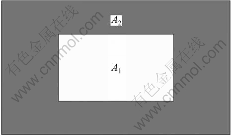
Fig. 3 Schematic diagram of exit slits
The OWC model with various exit opening percentages was tested at a depth of 0.29 m at frequencies of 0.8-1.0 Hz with increments of 0.1 Hz. A five-bladed Savonius type rotor was designed and constructed from aluminum and is shown in Fig. 4. The blade of the Savonius rotor is made of aluminum at an angle of 70�� and length of 0.19 m. The shaft was made with mild steel of radius of 0.015 m.
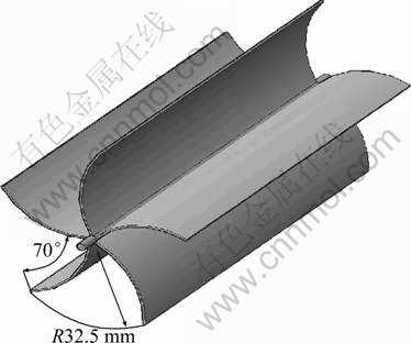
Fig. 4 Geometric details of five-bladed Savonius rotor
3 Results and discussion
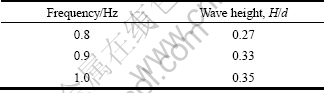
Table 1 gives the wave maker frequency and the non-dimensionalized wave height for which the tests were carried out. The water depth in these conditions was 0.29 m.
Table 1 Wave heights as a ratio of depth at various wave maker frequencies
3.1 Static pressure
The results of the static pressure for the OWC with different exit opening percentages are analyzed and presented. Figure 5 shows the static pressure for OWC with different exit opening percentages at depth of 0.29 m at a frequency of 1.0 Hz. The static pressure reading was taken at Tap B shown in Fig. 2 which was located at the turbine section towards the exit. It can be seen in Fig. 5 that the static pressure for the OWC with exit opening of 0% (full blockage) was very high compared to the other exit opening percentages. This is due to full blockage of the exit which does not allow any air inside the chamber to exit. This blockage causes a lot of air particle collisions inside the OWC chamber, resulting in higher static pressure.
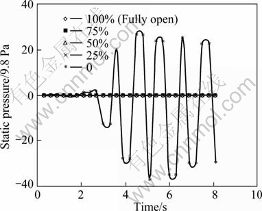
Fig. 5 Variation of static pressure with respect to period at water depth of 0.29 m at frequency of 1.0 Hz at Tap B
Figure 6 is the same as Fig. 5 without the exit opening percentage of 0%. In Fig. 6, it can be seen that the static pressure for the OWC with exit opening percentages of 25% had slighter higher pressure values than OWC with other exit opening percentages (50%, 75% and 100%). This is due to the same reason mentioned previously.
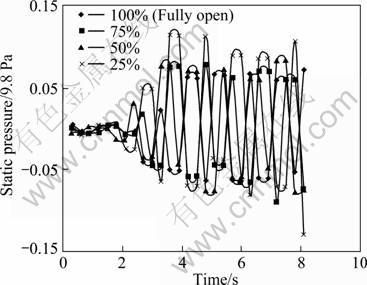
Fig. 6 Variation of static pressure with respect to period at water depth of 0.29 m at frequency of 1.0 Hz at Tap B
3.2 Dynamic pressure
The results of the dynamic pressure for the OWC with different exit opening percentages are analyzed and presented. Figure 7 shows the dynamic pressure for OWC with different exit opening percentages at depth of 0.29 m at a frequency of 1.0 Hz. The dynamic pressure reading was taken at Tap B shown in Fig. 2 which was located at the turbine section towards the exit. It can be seen in Fig. 7 that the dynamic pressure for the OWC with exit opening of 100% (no blockage) was very high compared to the other exit opening percentages. Also, the OWC with the exit opening of 75% had high dynamic pressure values compared to the OWC with slit configurations of 50%, 25% and 0%. This is due to greater size of opening at the exit which lets the air move freely inside the OWC. The OWC with less exit opening percentages (50%, 25% and 0%) have lower dynamic pressure due to the fact that blockage increases the amount of air particle collisions inside the OWC chamber, resulting in lower values of dynamic pressure.
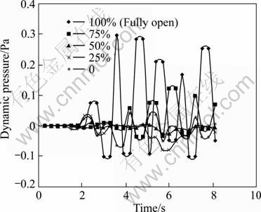
Fig. 7 Variation of dynamic pressure with respect to period at water depth of 0.29 m at frequency of 1.0 Hz at Tap B
3.3 Rotational speed
The results of the rotational speed for the OWC model with different exit opening percentages are analyzed and presented. Table 2 gives the rotational speed of the Savonius rotor at different frequencies and different OWC exit opening percentages. The frequencies used were 0.8, 0.9 and 1.0 Hz at water depth of 0.29 m. These ranges of frequencies were chosen since they produce high amplitude waves. The high amplitude waves oscillate inside the OWC chamber, causing the air inside the chamber to get compressed and thus rotating the turbine.
Table 2 Rotational speed of Savonius rotor for different exit opening percentages at different frequencies (r/min)
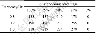
According to the results in Table 2, it could be seen that for the OWC exit openings of 100% and 75%, there is very little difference in the rotational speed values. The reason for this is the exit opening percentage given by the formula A1/A2, where A1 is the area of the inner rectangle and A2 is the area of the outer rectangle (original exit dimension). According to this formula, there is very little difference between the exit opening percentage of 100% and 75% since the original exit dimensions were scaled down equally. The 50% exit opening also shows a little difference in rotational speed for frequencies of 0.8 Hz and 1.0 Hz but it shows larger difference for frequency of 0.9 Hz. The largest increase in rotational speed was seen in the 25% exit opening.
This was due to the small opening of 25% at the exit. The compressed air from the OWC chamber is forced out in this small exit thus the air speed in the turbine section increases causing the turbine to rotate faster, thus having a higher value of rotational speed. This is the same when the air is sucked in from the exit. The air is forced inside the small opening increasing the velocity of air and causing the turbine to rotate faster. Figure 8 shows the rotational speed of the Savonius rotor for different frequencies and slit configurations.
3.4 Static pressure drop across turbine
The results of the static pressure drop across turbine for the OWC with different exit opening percentages are analyzed and presented. Figure 9 shows the static pressure for OWC with exit opening percentages at depth of 0.29 m at a frequency of 0.8 Hz. The static pressure drop reading was taken at Tap A and Tap B shown in Fig. 2. As seen in Fig. 9, the pressure drop across the turbine for OWC with the exit opening of 100% increases initially and then decreases. According to the actuator disc theory, the static pressure drops rapidly across a turbine. The pressure drop can be used to approximate the drag on the turbine which can indicate the energy imparted to the turbine by the air. Decrease in pressure difference results in less power being extracted. For the OWC, the positive pressure drop indicates the drop during suction stage while the negative one indicates the drop during exhalation stage. It could be seen from Fig. 9 that OWC with exit opening of 0% has very less pressure drop. The amplitude of pressure drop oscillation is almost zero initially and as the chamber oscillations build up the pressures go to peak before reducing again to maintain a settled or stationary oscillation. This behavior is typical of OWC devices [6]. For the greater percentage openings (100%, 75% and 50%), the initial pressure drop is very high compared to the 25% and 0% opening. The 0% opening pressure drop maintains low amplitude, larger openings such as 100%, 75% and 50% have reduced pressure drops afterwards, and the 25% pressure drop maintains its amplitude throughout.
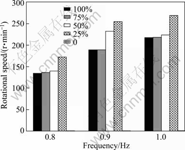
Fig. 8 Variation of rotational speed of Savonius rotor with respect to frequency at water depth of 0.29 m
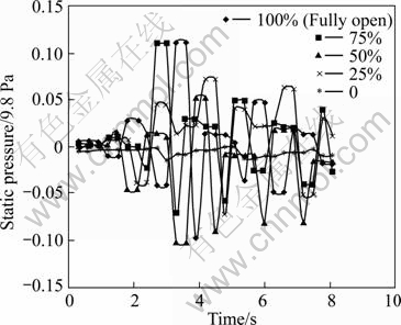
Fig. 9 Static pressure drop across turbine with respect to period at water depth of 0.29 m at frequency of 0.8 Hz
3.5 Coefficient of power
According to MENET [23], the power curve of a Savonius rotor can be represented by an analytical equation CP=f(��), where CP is the power coefficient and �� the speed ratio. Since f is approximated by a parabola, the power coefficient can be written as
![]() (1)
(1)
where �� is the angular velocity of the rotor (rad/s), R is the radius of the rotor and v is the air velocity that can be determined from the dynamic pressure oscillations.
The results of coefficient of power for the OWC with different exit opening percentages are analyzed and presented. Table 3 gives the coefficient of power for OWC with different exit opening percentages at depth of 0.29 m at frequencies of 0.8, 0.9 and 1.0 Hz.
Table 3 Coefficient of power for different exit opening percentage at different frequencies
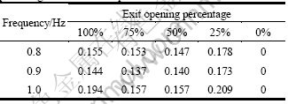
The highest CP was achieved at 25% opening at 1 Hz while lower CP values were registered for 0.9 Hz frequency at all other openings except for 25%, as shown in Fig. 10.
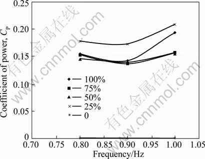
Fig. 10 Coefficient of power for different exit opening percentages at different frequencies
The CP value is graphed against the tip speed ratio of the turbine in Fig. 11 for the exhalation stage of the OWC. For its use in the OWC, the CP values are seen to reduce at a tip speed ratio �� of 0.35. Afterwards from 0.35, the CP increases. For a conventional CP vs �� graph, the CP would rise up till a certain �� before reducing in a parabolic fashion. However, higher tip speed ratios were not tested to confirm this.
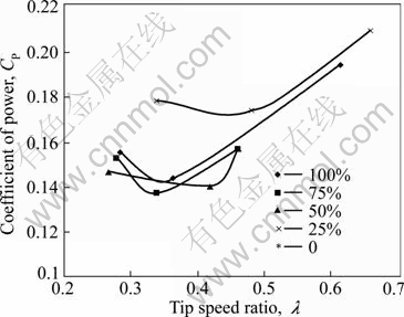
Fig. 11 Coefficient of power for different exit opening percentages at different tip speed ratio
4 Conclusions
A rectangular OWC employing a Savonius rotor was used to study the effect of turbine duct exit opening. The Savonius rotor operated at different wave conditions. After testing at opening of 0%, 25%, 50%, 75% and 100%, it was seen that with a 25% opening the OWC performed better compared to a 100% open case. This can be attributed to the tuning of the oscillation devices at this opening to match the natural frequency of the device. The static pressure results show high values of static pressure for 0% opening compared to other exit opening percentages. The static pressure value for 25% opening was a little higher compared to 50%, 75% and 100% opening percentages. The dynamic pressure results show high values of dynamic pressure for 100% opening compared to other opening percentages. The OWC with 25% and 0% opening shows very low dynamic pressure values. The rotational speed is the highest at 25% exit opening in all frequencies tested. The CP values for the 25% opening are also higher going up to 0.209. Overall, it is seen that the turbine exit opening has a lot of effect on the performance of OWC. This fact can be used to tune the device to different sea states, by dynamically controlling the turbine exit opening.
References
[1] SMITH G H, VENUGOPAL V. The effect of wave period filtering on wave power [J]. Ocean Engineering, 2007, 34: 1120-1137.
[2] PELC R, FUJITA R M. Renewable energy from the ocean [J]. Marine Policy, 2002, 26: 471-479.
[3] FALCAO A F D O. First-generation wave power plant: Current status and R & D requirements [C]// International Conference on Offshore Mechanics and Arctic Engineering (OMAE). Cancun. 2003: 723-731.
[4] CLEMENT A, MCCULLEN P, FALCAO A, FIORENTINO A, GARDNER F, HAMMARLUND K, LEMONIS G, LEWIS T, NIELSEN K, PETRONCINI S, PONTES M T, SCHILD P, SJOSTROM B O, SORENSEN H S, THORPE T. Wave energy in Europe: Current status and perspectives [J]. Renewable and Sustainable Energy Reviews, 2002, 6: 405-431.
[5] BRITO-MELO A, GATO L M C, SARMENTO A J N A. Analysis of Wells turbine design parameters by numerical simulation of the OWC performance [J]. Ocean Engineering, 2002, 29: 1463-1477.
[6] GRAW K. Scale 1:10 wave flume experiments on IIT oscillating water column wave energy device [C]// ODEC, 1993: 26-27.
[7] FALCAO A F D O, JUSTINO P A P. OWC wave energy devices with air flow control [J]. Ocean Engineering, 1999, 26: 1275-1295.
[8] GATO L M C, PAIXA?O CONDE J M. Numerical study of the air-flow in an oscillating water column wave energy converter [J]. Renewable Energy, 2008, 33(12): 2637-2644.
[9] CAMPOREALE S M, STRIPPOLI P D, PASCAZIO G, TORRESI M. Accurate numerical simulation of a high solidity Wells turbine [J]. Renewable Energy, 2008, 33(4): 735-747.
[10] SETOGUCHI T, TAKAO M. Current status of self rectifying air turbines for wave energy conversion [J]. Energy Conversion and Management, 2006, 47: 2382-2396.
[11] LIU Z, HYUON B, SHI H, HONG K. Practical simulation of oscillating water column chamber for wave energy conversion [J]. International Journal of Green Energy, 2010, 7: 337-346.
[12] RAM K, ZULLAH M A, AHMED M R, LEE Y H. Experimental studies on the flow characteristics in an inclined bend free OWC device with parallel walls [C]// International Conference on Renewable Energy. Yokohama, 2010: O-Oc-1-6.
[13] SANTHAKUMAR S, MAEDA H, TAKAO M, SETOGUCHI T. A review of impulse turbines for wave energy conversion [J]. Renewable Energy, 2001, 23: 261-292.
[14] SETOGUCHI T, KINOUE Y, TAKAO K K M. Wells turbine with end plates for wave energy conversion [J]. Ocean Engineering, 2007, 34: 1790-1795.
[15] MALA K, JAYARAJ J, JAYANSHANKAR V, MURUGANANDAM T M, SANTHAKUMAR S, RAVINDRAN M, SETOGUCHI T, TAKAO M, TOYOTA K, NAGATA S. A twin unidirectional impulse turbine topology for OWC based wave energy plants [J]. Renewable Energy, 2009, 34: 692-698.
[16] RAVINDRAN M, JAYASHANKAR V, JALIHAL P, PATHAK A G. The Indian wave energy program�Can overview [J]. Teri Information Digest on Energy (TIDE), 1997, 7: 88-173.
[17] OHONO H, FUNAKOSHI T, SAITO K, OIKAWA K, TAKAHASHI S. Interim report on the second stage of field experiments on a wave power extracting caisson in Sakata Port [R]. ODEC. 1993: 172-182.
[18] CURAN R, STEWART T P, WHITTAKER T J T. Design synthesis of oscillating water column wave energy converters: Performance Matching [J]. Proceedings of the Institute of Mechanical Engineers Part A �C Journal of Power and Energy, 1997, 211: 489-505.
[19] LIN C C, DORRELL D G. A small segmented oscillating water column using a Savonius rotor turbine [C]// IEEE International Conference on Sustainable Energy Technologies (ICSET). Singapore, 2008: 508-513.
[20] DORRELL D G, FILLET W. Investigation of a small-scale segmented oscillating water column utilizing a Savonius rotor turbine [C]// International Conference on Energy and Environment (ICEE). Malaysia, 2008: 23-32.
[21] DORRELL D G, HSIEH M F, LIN C C. Investigation of a small-scale segmented oscillating water column utilizing a Savonius rotor turbine [J]. IEEE Transactions on Industry Applications, 2010, 46: 2080-2088.
[22] PATEL S K, RAM K, AHMED M R, LEE Y H. Performance studies on an oscillating water column employing a Savonius rotor [J]. Science China-Technological Sciences, 2011, 54: 1674-1679.
[23] MENET J L. A double-step Savonius rotor for local production of electricity [J]. Renewable Energy, 2004, 29: 1843-1862.
[24] PERCIVAL M C, LEUNG P S, DATTA P K. The development of a vertical turbine for domestic electricity generation [J]. European Wind Energy Conference. London, 2004: 1-10.
[25] ALTAN B D, ATILGAN M. The use of a curtain design to increase the performance level of a Savonius wind rotors [J]. Renewable Energy, 2010, 35: 821-892.
[26] KOOLA P M, RAVINDRAN M, NARAYANA P A A. Model studies of oscillating water column wave-energy device [J]. ASCE Journal of Energy Engineering, 1995, 121: 14-26.
[27] RAM K, FAIZAL M, AHMED M R, LEE Y H. Experimental studies on the flow characteristics in an oscillating water column device, Journal of Mechanical Science and Technology, 2010, 24: 2043-2050.
(Edited by YANG Bing)
Received date: 2011-07-26; Accepted date: 2011-11-14
Corresponding author: M. Rafiuddin Ahmed, Associate Professor; Tel: +679-3232042; E-mail: ahmed_r@usp.ac.fj

