Boussinesq equation-based model for flow in drainage layer of highway
来源期刊:中南大学学报(英文版)2012年第8期
论文作者:但汉成 罗苏平 李亮 赵炼恒
文章页码:2365 - 2372
Key words:drainage layer; highway; groundwater; Boussinesq equation; seepage face
Abstract: In order to study the water flow in the drainage layer of highway under steady-state condition, one-dimensional (1D) Boussinesq equation-based model with Dupuit-Forchheimer assumption was established and the semi-analytical solutions to predict the water-table height were presented. In order to validate the model, a two-dimensional (2D) saturated flow model based on the Laplace equation was applied for the purpose of the model comparison. The water-table elevations predicted by 1D Boussinesq equation-based model and 2D Laplace equation-based model match each other well, which indicates that the horizontal flow in drainage layer is dominated. Also, it validates the 1D Boussinesq equation-based model which can be applied to predict the water-table elevation in drainage layer. Further, the analysis was conducted to examine the effect of infiltration rate, hydraulic conductivity and slope of drainage layer on the water-table elevation. The results show that water-table falls down as the ratio of Is to K decreases and the slope increases. If the aquifer becomes confined by the top of drainage layer due to the larger ratio of Is to K or smaller slope, the solution presented in this work can also be applied to approximate the water-table elevation in unconfined sub-section as well as hydraulic head in the confined sub-section.
J. Cent. South Univ. (2012) 19: 2365-2372
DOI: 10.1007/s11771-012-1283-z![]()
DAN Han-cheng(但汉成)1, 2, LUO Su-ping(罗苏平)1, 3, LI Liang(李亮)1, ZHAO Lian-heng(赵炼恒)1
1. School of Civil Engineering, Central South University, Changsha 410075, China;
2. Guizhou Transportation Planning Survey & Design Academe Co., Ltd., Guiyang 550001, China;
3. Administration of Quality Supervision of Hainan Transportation Engineering, Haikou 571100, China
? Central South University Press and Springer-Verlag Berlin Heidelberg 2012
Abstract: In order to study the water flow in the drainage layer of highway under steady-state condition, one-dimensional (1D) Boussinesq equation-based model with Dupuit-Forchheimer assumption was established and the semi-analytical solutions to predict the water-table height were presented. In order to validate the model, a two-dimensional (2D) saturated flow model based on the Laplace equation was applied for the purpose of the model comparison. The water-table elevations predicted by 1D Boussinesq equation-based model and 2D Laplace equation-based model match each other well, which indicates that the horizontal flow in drainage layer is dominated. Also, it validates the 1D Boussinesq equation-based model which can be applied to predict the water-table elevation in drainage layer. Further, the analysis was conducted to examine the effect of infiltration rate, hydraulic conductivity and slope of drainage layer on the water-table elevation. The results show that water-table falls down as the ratio of Is to K decreases and the slope increases. If the aquifer becomes confined by the top of drainage layer due to the larger ratio of Is to K or smaller slope, the solution presented in this work can also be applied to approximate the water-table elevation in unconfined sub-section as well as hydraulic head in the confined sub-section.
Key words: drainage layer; highway; groundwater; Boussinesq equation; seepage face
1 Introduction
Water can infiltrate into the pavement structure mainly through the cracks distributed in pavement surface, which would cause and accelerate the pavement damage. Therefore, drainage efficiency plays an important role in the performance of roadway pavements. Generally speaking, pavement drainage systems consisting of inner drains and edge drains are frequently used in China and many other countries [1-2]. Drainage layer in pavement which is a kind of inner drains can drain the accumulated water promptly, and it is useful to promote the service performance and greatly prolong service life, thereby acquiring considerably economic benefit [3-5]. Some comparison analysis and observation results have shown that the service life of pavement with the drainage layer or permeable base can be improved by up to approximately 30% in concrete pavement and about 50% in asphalt pavement respectively compared with that of pavement without drainage layer [6].
The leaking water through the surface course may accumulate in the drainage layer, thereby forming a groundwater table. The elevation of this perched groundwater table has been used as an indicator for the effectiveness of the drainage layer i.e. a relatively low groundwater table reflects an effective drainage design [7-9]. The engineering design of highway drainage, typically based on steady-state flow conditions, requires the flow capacity of the drainage layer to be equal to or greater than the inflow from the design infiltration rate. The drainage layer thickness should not be less than the computed flow depth. In other words, the groundwater table under the steady-state drainage flow condition is not allowed to exceed the top elevation of the drainage layer.
In order to study the characteristic of drainage, this problem of flow in drainage layer was regarded as that of subsurface flow in groundwater. The Dupuit- Forchheimer approximation is conventionally used in investigations of the two-dimensional (2D) groundwater problem presented by flow of transverse drains due to steady rainfall on the surface of lands overlying a moderately sloping impermeable base. As shown by TOWNER [10] for drains along contours and by YOUNGS and RUSHTON [11] for the present drainage situation for a uniform soil, there is a little difference in the results assuming horizontal flow and those assuming flow parallel to the sloping bed when the slope is less than 10%. CEDERGREN [12] described approximate relationships to estimate the spacing of drains dependent on the rainfall intensity and permeability of the underlying layer; his analysis was refined by preparing flow nets to describe the flow. In one significant study, CEDERGREN [12] showed the advantages of increasing the slope of the subgrade to improve the effectiveness of the drainage. However, no detailed study has been presented on the water flow in drainage layer of highway.
In terms of drainage engineering, studies on seepage analysis [13-14] gave an exact formulation of the problem of groundwater flow in layered soils, leading to estimates of bounds for the water-table elevation. This exact analysis was extended to groundwater flow in layered sloping lands [15], but did not provide solutions for the water-table elevation. Analysis for steady-state ditch drainage in sloping railway bed [16] was conducted with simplified Dupuit-Forchheimer equation, but the results were found not to be in good agreement near the drainage ditches and it cannot deal with the case that the water-table doesn’t span the whole drainage layer. It is significant that MIZUMURA [17] experimentally and theoretically derived the boundary condition of the unconfined ground water flow at the drawndown end.
Based on the previous studies, this work aims to study the water flow in the drainage layer under steady- state condition and predict the water-table elevation with the changes of infiltration rates, hydraulic conductivities of drainage layers and slopes of pavement.
2 Methodology
The two-dimensional (2D) flow region through a cross section of the two layers was considered and sketched in Fig. 1. The surface course overlies a drainage layer which overlies an impermeable base (Generally, it is semi-rigid base) where slopes downwards (towards right). The domain consists of a lower layer with hydraulic conductivity K overlain by a less impermeable layer with hydraulic conductivity. There is uniform steady rainfall over the surface course which drains at x=±D to a ditch. The rainfall maintains the water-table at a height H(x) above the data at position x over the area. Above the outfall water level assumed as zero at x=D, a seepage face is formed as an exit with a height of hf.
2.1 Model setup and solution derivation
In order to obtain the analytical solution, several assumptions were made herein first:
1) Seepage is steady state and laminar flow;
2) Horizontal flow is negligible in unsaturated zone;
3) The infiltration is constant;
4) Dupuit-Forchheimer approximation is valid.
Thus, the one-dimensional (1D) Boussinesq equation with vertical flow neglected (BM) can be simplified as
![]() (1)
(1)
where f=(D-x)tanθ, and D is horizontal length of drainage layer, m; θ is slope angle, (°); K is hydraulic conductivity of drainage layer, m/s; Is is infiltration rate (m/s) which represents the water infiltrating into the drainage layer per unit area.
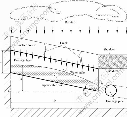
Fig. 1 Schematic diagram of drainage system of highway pavement
Since the flow is in steady state, the water quantity of infiltration should be equal to that of discharge, thus, it can be obtained as
![]() (2)
(2)
with w defined by
![]() (3)
(3)
![]() (4)
(4)
Thus, Eq. (2) can be rewritten as
![]() (5)
(5)
According to Eq. (3), it can be obtained that
![]() (6)
(6)
Substituting Eq. (6) into Eq. (5) and making a simplification, Eq. (6) becomes
![]() (7)
(7)
After integration, x as a function of w is given by
![]() (8)
(8)
where the lower integration limit of w is wi, at x=x(wi).
Noting that
![]()
![]() (9)
(9)
The solution of Eq. (8) can be rewritten, which is in the form of
![]() (10)
(10)
Compared with Eq. (9) and according to Eq. (8), the parameters can be obtained which are a=1, b=-tan θ and c=ψ.
In terms of the solution according to Eq. (9), it can be fallen into three cases to derive the solution of water-table elevation in drainage layer as follows:
Case 1: If ![]() the water-table is horizontal at a height
the water-table is horizontal at a height ![]() above the impermeable base at x=0 where w=∞. Moreover, the flux at x=0 is zero and the gradient dH/dx is zero correspondingly (no flow boundary). Thus, the expression of F(w) can be given by
above the impermeable base at x=0 where w=∞. Moreover, the flux at x=0 is zero and the gradient dH/dx is zero correspondingly (no flow boundary). Thus, the expression of F(w) can be given by
![]()
![]() (11)
(11)
Case 2: If ![]()
![]() (the level of impermeable base) at x=0. The gradient dH/dx at x=0 becomes increasingly more negative and w decreases to a finite value from ∞. Accordingly, the expression of F(w) in this case can be given by
(the level of impermeable base) at x=0. The gradient dH/dx at x=0 becomes increasingly more negative and w decreases to a finite value from ∞. Accordingly, the expression of F(w) in this case can be given by
![]() (12)
(12)
Case 3: In reality, there is a third case, i.e., ![]() 0. In this case, I is such small that the developed saturated zone does not span the whole domain. In other words, the water-table intersects the base at a distance (x0) down from the upper boundary (x=0, as shown in Fig. 2). To derive an analytical solution for this case (which has not been considered previously), it is noted that the water-table behaves the same as that in the second case except for the difference in its intersection with the base. To account for such a difference and retain the mass conservation, the infiltration rate can be re-adjusted by redistributing the infiltrating water in the area between x=0 and x0 to the flow zone from x=x0 to D uniformly. Thus, the adjusted infiltration rate (between x0 and D) is given by
0. In this case, I is such small that the developed saturated zone does not span the whole domain. In other words, the water-table intersects the base at a distance (x0) down from the upper boundary (x=0, as shown in Fig. 2). To derive an analytical solution for this case (which has not been considered previously), it is noted that the water-table behaves the same as that in the second case except for the difference in its intersection with the base. To account for such a difference and retain the mass conservation, the infiltration rate can be re-adjusted by redistributing the infiltrating water in the area between x=0 and x0 to the flow zone from x=x0 to D uniformly. Thus, the adjusted infiltration rate (between x0 and D) is given by
![]() (13)
(13)
In this case, x0 can be determined (see Eq. (14)) by solving the equation of ![]() where
where ![]()
![]()
![]() (14)
(14)

Fig. 2 Schematic diagram showing approach to adjust infiltration rate along drainage layer: (a) Uniform initial infiltration rate; (b) Adjusted infiltration rate
Then, this case can be transferred into Case 2 with the length of the drainage layer D replaced by (D-x0). Thus, the solution for Case 2 can be applied to Case 3 to compute the water-table elevation H for x from x0 to D.
In Eq. (10), the wi can be obtained from Eq. (3) for the given value of H at x(wi). With Eq. (10) giving the coordinates x as a function of w, the height of water-table H at a given x can be expressed as
![]() (15)
(15)
2.2 Boundary condition setup
When the Dupuit-Forchheimer approximation is applied, conditions on the downstream boundary must be represented by a single head HD. The conventional approach is to use the external downstream groundwater level with HD=h0=0 [18]; this results in a water-table which is too low in the vicinity of the downstream face. This violates the actual situation observed by HEYNS [19]. In an alternative approach, HD is set equal to hf according to the experimental and theoretical results [20]. Since the Dupuit-Forchheimer formulation results in a 1D equation, only one condition can be specified at the downstream boundary. Thus, if the height of the seepage face is estimated, the water-table can be calculated.
The following equation as the downstream boundary condition is experimentally and theoretically derived at the drawdown end x=D [17, 20]:
![]() (16)
(16)
where h is the thickness of water-table normal to impermeable-base bottom; x′ is coordinate parallel to the sloping impermeable base of the bottom; D′ is length of the unconfined aquifer in x′ direction; So is bottom slope of the aquifer which is tan θ.
Assuming that the pressure is hydrostatic in the unconfined groundwater flow, the piezometric head H at x′ is given as
![]() (17)
(17)
where z is vertical coordinate above the datum. The hydraulic gradient at x is written as
![]() (18)
(18)
According to the derivation of YOUNGS and RUSHTON [16], Eq. (19) can be obtained:
![]() (19)
(19)
Thus, the gradient at x=D from Eq. (16) can be expressed as
![]() (20)
(20)
Since
![]() (21)
(21)
we have
![]() (22)
(22)
where hf is the approximate height of seepage face.
Accordingly, the boundary condition can be applied as below to the system:
 (23)
(23)
![]() (24)
(24)
As such, it can be fallen into three cases which are taken into consideration as
Case 1: If ![]() ,
,
![]()
![]()
 (25)
(25)
Case 2: If ![]() ,
,
 (26)
(26)
Case 3: If ![]() ,
,
![]()
 (27)
(27)
In Case 3, Eq. (24) is not correct to calculate the x(w) and should be replaced by the equation as
![]() (28)
(28)
2.3 Maximum thickness of saturated zone above impermeable base
The thickness of saturated zone above the impermeable base vary with the distance x can be expressed as
![]() (29)
(29)
If there is a line which is tangent to the water-table line, it should be parallel to the level of bottom of impermeable base; in other words, the gradient of water-table at x should be equal to![]() . The location (x coordinate) at the tangency point is the position of the maximum thickness of saturated zone.
. The location (x coordinate) at the tangency point is the position of the maximum thickness of saturated zone.
According to Eq. (6), the gradient of tangent line at x can be given by
![]() (30)
(30)
And
![]() (31)
(31)
Thus, Eq. (30) can be rewritten as
 (32)
(32)
![]() (33)
(33)
Therefore,
![]() (34)
(34)
![]() (35)
(35)
and
![]() (36)
(36)
Accordingly, xm and Tm can be calculated by the Eq. (24) and Eq. (36) in Case 1 and Case 2, respectively; while in Case 3, ![]() herein xm can be calculated by Eq. (24).
herein xm can be calculated by Eq. (24).
3 Model validation and discussion
In order to validate the model (BM), a 2D saturated flow model based on the Laplace equation (LM) [21] was also used for the purpose of the model comparison:
![]() (37)
(37)
The groundwater modelling system [22] was employed to solve the governing equation for the 2D model (LM). In the simulation, the left hand side boundary (x=0) and the impermeable base were set to be no-flow boundaries. A specified flux boundary (based on the infiltration rate Is) was applied on the top of the drainage layer. The right hand side boundary was set as a potential flux boundary which allowed the development of the seepage face (Fig. 1).
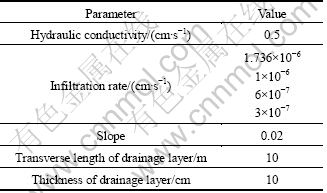
Unstructured meshes with around ten thousand triangle elements were used in the numerical models. For all the simulations, tests on the solution’s independence of mesh size were conducted. Smaller mesh size than that used in the solutions presented here did not improve the solutions significantly. Thus, the results presented here are considered to be “converged” numerical solutions at the steady-state. The values of parameters [23] used in simulation are given in Table 1.
Table 1 Parameter values for model validation
From Fig. 3, it can be seen that the water-table elevations predicted by LM and our solution match each other well, which shows that the model presented here is valid and the solution is reliable. The model is presented in this work with vertical flow neglected (Dupuit- Forchheimer assumption); whereas the LM is a model incorporating horizontal flow and vertical flow. Therefore, the comparison results indicate the water flow in drainage layer is dominated by horizontal flow, which proves that the Dupuit-Forchheimer assumption is valid as well in drainage layer.
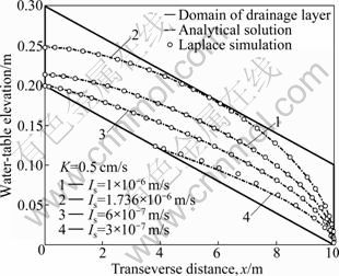
Fig. 3 Water-table elevation under different infiltration rates at steady state
Moreover, it also shows the difference of water- table elevations calculated by LM and approximate method in Case 3 when the infiltration rate is relatively small (K=0.5 cm/s, and Is=3×10⁻⁷ m/s); however, the accuracy is acceptable.
In order to examine the effects of infiltration rate (Is), hydraulic conductivity (K) and slope of drainage layer on the water-table elevation, the calculation and comparison were conducted and three slopes were considered, as listed in Table 2. Since the infiltration rate and hydraulic conductivity play opposite roles in variety of water-table elevation, the ratio of infiltration rate to hydraulic conductivity (Is/K) is taken into consideration. The scenarios and parameter values are listed in Table 2, and the calculated results are illustrated in Figs. 4 to 6.
Additionally, the maximum thickness of saturated zone and the location of maximum thickness of saturated zone were obtained; meanwhile, if the water-table intersects with the bottom of drainage layer, the location of intersect point was calculated as well. All of them are listed in Table 2.
3.1 Effect of Is/K on water-table elevation
From Figs. 4-6, it can be seen that the Is/K plays an significant role in the water-table elevation. The water-table falls down with the ratio of Is to K decreasing. In Fig. 4, the value of Is/K is 2×10⁻⁶ m/s, slope (r) is 0.02, and the aquifer becomes partially confined by the top of drainage layer. From the comparison of water-table elevation predicted by LM (represented by “o”) and semi-analytical solution, it can be seen that the water-table matches each other well. This indicates that the 1D Boussinesq equation-based model can be applied to approximate the water-table elevation in unconfined sub-section and hydraulic head in the confined sub- section.
3.2 Effect of slope on water-table elevation
It can be seen from the comparison from Figs. 4-6, the water-table elevation decreases with the slope increasing. For Is/K is 1×10⁻⁶ m/s, in Fig. 4, the water- table spans the whole domain (Case 1), while in Figs. 5 and 6, the water-tables intersect with the bottom of drainage layer. The locations are about 5.6 m and 7.5 m corresponding to Fig. 5 and Fig. 6, respectively. This illustrates the intersected point locates downwards to the downstream of drainage direction as the slope increases. The sloping drainage layers with larger slope are subjected to more significant gravity effect and thus achieve improved drainage performance.
Table 2 Parameter values used in calculation
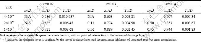
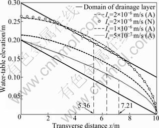
Fig. 4 Water-table prediction in different Is/K at r=0.02 (A- Analytical solution; N-Numerical solution)
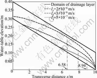
Fig. 5 Water-table prediction in different Is/K at r=0.03
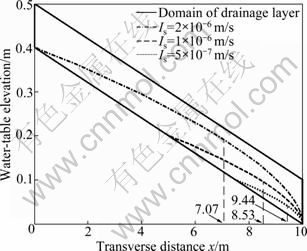
Fig. 6 Water-table prediction in different Is/K at r= 0.04
Figure 7 shows the maximum thickness of saturated zone (Tm) and their locations varying with the ratio of infiltration rate to hydraulic conductivity and slope. It is obvious that the maximum thickness of saturated zone grows up with the increase of Is/K and falls down with the increase of the pavement slope (or slope of drainage layer). The horizontal location of Tm is downwards to the lower boundary of drainage layer with the slope increasing and the Is/K decreasing.

Fig. 7 Xm and Tm vary with ratio of Is to K and slope
Based on the comparison results, the development of cracks in pavement and clogging of drainage layer will result in the elevation of water-table thereby being confined by the top of drainage layer. Moreover, the water flow condition such as Cases 1, 2 and 3 are transformable according to the value of Is/K and the slope of drainage layer.
4 Conclusions
1) The comparison results calculated by Laplace equation and Boussinewq equation indicate that the water flow in drainage layer is dominated by horizontal flow, which proves that the Dupuit-Forchheimer assumption is valid in drainage layer.
2) The water-table falls down with the ratio of Is to K decreasing. If the ratio is large enough, the aquifer will become confined by the top of drainage layer. Under this condition, the solution presented can be applied to approximate the water-table elevation in unconfined sub-section and hydraulic head in the confined sub-section.
3) The sloping drainage layers with larger slope are subjected to more significant gravity effect and thus achieve improved drainage performance.
4) The present study focuses on steady-state flows in the drainage layer assuming a constant and uniform rate of infiltration from the surface course. In reality, the flow processes involved in the drainage system of highway pavement are more complicated. There is a need to investigate transient flow conditions in terms of “time-to-drain”. Additionally, the surface course is subjected to overland flow (surface flow), which affects the infiltration through the cracks, and interacts with the subsurface flow in the drainage layer. Future studies on the coupling of these dynamic flow processes would likely produce more insights into the drainage characteristics of the highway pavement system, which will help to improve further the engineering design of such a system.
References
[1] RABAB’AH S, LIANG R Y. Finite element modeling of field performance of permeable bases under asphalt pavement [J]. Transportation Research Record, 2007, 2004: 163-172.
[2] YANG X L, YIN J H. Slope stability analysis with nonlinear failure criterion [J]. Journal of Engineering Mechanics, 2004, 130(3): 267-273.
[3] RAY M, CHRISTORY J P. Combating concrete pavement slab pumping: Stateof-the-art and recommendations [C]// Proceedings of 4th International Conference on Concrete Pavement Design and Rehabilitation. West Lafayette: Purdue University, 1989: 725-733.
[4] YANG X L, SUI Z R. Seismic failure mechanisms for loaded slopes with associated and nonassociated flow rules [J]. Journal of Central South University of Technology, 2008, 15(2): 276-279.
[5] CHRISTOPHER B R, MCGUFFEY V C. Pavement subsurface drainage systems [M]. Washington D C: Transportation Research Record, 1997: 48-51.
[6] MATHIS D M. Permeable base design and construction [C]// The 4th International Conference on Concrete Pavement Design and Rehabilitation. West Lafayette: Purdue University, 1989: 663-670.
[7] MOULTON L K. Groundwater, seepage, and drainage: A Textbook on groundwater and seepage theory and its application [M]. New York, USA: Wiley, 1979: 201-322.
[8] YANG X L. Seismic bearing capacity of a strip footing on rock slopes [J]. Canadian Geotechnical Journal, 2009, 46(8): 943-954.
[9] YANG X L, YIN J H. Slope equivalent Mohr-Coulomb strength parameters for rock masses satisfying the Hoek-Brown criterion [J]. Rock Mechanics and Rock Engineering, 2010, 43(4): 505-511.
[10] TOWNER G D. Drainage of groundwater resting on a sloping bed with uniform rainfall [J]. Water Resources Research, 1975, 11(1): 144-147.
[11] YOUNGS E G, RUSHTON K R. Dupuit-Forchheimer analyses of steady-state water-table heights due to accretion in drained lands overlying undulating sloping impermeable beds [J]. Journal of Irrigation and Drainage Engineering, 2009, 135(4): 467-473.
[12] CEDERGREN H R. Seepage, drainage and flow nets [M]. New York, USA: Wiley, 1967: 252-475.
[13] YOUNGS E G. Horizontal seepage through unconfined aquifers with hydraulic conductivity varing with depth [J]. Journal of Hydrology, 1965, 3(3/4): 283-296.
[14] YOUNGS E G. Exact analysis of certain problems of ground-water flow with free surface conditions [J]. Journal of Hydrology, 1966, 4: 277-281.
[15] YOUNGS E G. Seepage through unconfined aquifers with lower boundaries of any shape [J]. Water Resources Research, 1971, 7(3): 624-631.
[16] YOUGNS E G, RUSHTON K R. Steady-state ditch-drainage of two-layered soil regions overlying an inverted V-shaped impermeable bed with examples of the drainage of ballast beneath railway tracks [J]. Journal of Hydrology (Amsterdam), 2009, 377(3/4): 367-376.
[17] MIZUMURA K. Theoretical boundary condition of groundwater flow at drawdown end [J]. Journal of Hydrologic Engineering, 2009, 14(10): 1165-1172.
[18] RUSHTON K R, GHATAORA G. Understanding and modelling drainage of railway ballast [J]. Proceedings of the Institution of Civil Engineers-Transport, 2009, 162(4): 227-236.
[19] HEYNS F J. Railway track drainage design techniques [D]. Department of Civil Environmental Engineering, Amherst: University of Massachusetts, 2000: 98-117.
[20] MIZUMURA K. Approximate solution of nonlinear boussinesq equation [J]. Journal of Hydrologic Engineering, 2009, 14(10): 1156-1164.
[21] BEAR J. Dynamics of fluids in porous media [M]. New York: American Elsevier Publishing Company, Inc., 1972: 361-362.
[22] GMS. Groundwater modeling system [M]. Utah: Brigham Young University, 2002: 1-489.
[23] STORMONT J, ZHOU S. Improving pavement sub-surface drainage systems by considering unsaturated water flow [R]. Albuquerque: University of New Mexico, 2001.
(Edited by DENG Lü-xiang)
Foundation item: Project(511114) supported by the Natural Science Foundation of Hainan Province, China; Project(2009YBFZ05) supported by Postgraduate Award of Central South University, China; Project(200731) supported by Traffic Technology Fund of Hunan Province, China; Project(2008BAG10B01) supported by the National Key Technology R&D Program, China
Received date: 2011-04-01; Accepted date: 2011-08-12
Corresponding author: LUO Su-ping, PhD Candidate; Tel: +86-13874934466; E-mail: danhancheng@gmail.com

