J. Cent. South Univ. (2016) 23: 1000-1006
DOI: 10.1007/s11771-016-3148-3

Numerical simulation of single bubble rising in shear-thinning fluids by level set method
LI Shao-bai(���ٰ�), YAN Zheng(����), LI Run-dong(����), WANG Lei(����), LUAN Jing-de(�ᄡ��)
Liaoning Key Laboratory of Clean Energy and College of Energy and Environment, Shenyang Aerospace University, Shenyang 110136, China
 Central South University Press and Springer-Verlag Berlin Heidelberg 2016
Abstract: the behavior of single bubble rising in quiescent shear-thinning fluids was investigated numerically by level set method. A number of bubbles in a large range of Reynolds number and Eotvos number were investigated including spherical, oblate and spherical. The bubble shape and drag coefficient were compared with experimental results. It is observed that the simulated results show good conformity to experimental results over a wide range of Reynolds number. In addition, the detailed flow field based on the reference coordinate system moving with the bubble is obtained, and the relationship among flow field, bubble shape and velocity is discussed.
Key words: single bubble; shear thinning fluid; numerical simulation; level set method
1 Introduction
The motion of a gas bubble in shear-thinning fluids is frequently encountered in chemical, biochemical, pharmaceutical, environment, food, and other industrial applications [1-3]. In all of the above-mentioned applications, one encounters bubble swarms rather than single bubble, but understanding of the hydrodynamics of a single bubble can provide an insight to applications involving bubble swarm, which therefore often serves as a useful starting point to undertake the modeling process. Thus, the knowledge about the fundamentals of hydrodynamics, particularly the velocity, shape and flow field of a single bubble rising in shear thinning fluids, is necessary for design and efficient operation of those processes.
In above-mentioned fundamentals of hydrodynamics, the velocity of single bubble is the most important parameter due to its effects on the average residence time of the gas phase. To calculate the velocity of single bubble, it is customary to present the dependence of the free rise velocity on the pertinent variables in terms of nondimensional groups, such as the Reynolds number and drag coefficient. In the case of shear thinning fluids, the viscosity term of the Reynolds number and drag coefficient are computed by certain rheological equations, including Power Law model, Cross model, Carreau model, and herein a number of correlations were further proposed [4-6]. However, those formulas are only applicable at low Reynolds number when the bubble shape can be viewed as sphere. As to large Reynolds number, the bubble is of oblate shape or even spherical cap [7]. In order to quantify the shape of bubble, Miyahara and YAMANAKA [8] introduced a concept of aspect ratio to characterize bubble shape, and proposed an empirical correlation on the basis of experimental results in order to predict the bubble aspect ratio. It is well known that the motion behavior of bubble in shear thinning fluids depends not only on fluid properties and bubble size, but also on the bubble shape. Generally, the shape of bubble rising in shear thinning fluids is oblate at large Reynolds number [9]. Logically, the drag of oblate bubble is certainly larger than that of spherical bubble at the same size [10]. Nevertheless, only a few studies on the bubble shape in shear thinning have been reported by now [11-12]. In our previous work [13], single bubbles rising in shear thinning fluids were investigated via experiments, and accordingly, the graph of bubble shape distribution in shear-thinning fluids was drawn. As well known that adequate understanding of the flow structure surrounding single bubble in shear thinning fluids is the essential basic for better understanding gas-liquid absorption processes with or without reactions as well as taking overall insight into the bubbles swarm behavior. Considering the importance of that, the flow structure surrounding a single bubble in shear thinning fluids has been studied by many researchers with visualization experiment and numerical simulation. At present, the research of this domain mainly focuses on velocity field [14-15], viscosity distribution [16-17], shear stress distribution and the averaged description of wake properties including shedding frequency, primary wake size, and bubble inclined angle [18-19].
In recent years, direct numerical simulation (DNS) technique has been proven as a reliable approach to gain extensive understanding of flow phenomena in two-phase flows of shear-thinning fluids. There are many different DNS models available in literature for bubble motion with deformable interfaces, such as the volume of fluid (VOF), level set, lattice Boltzmann (LB) and the front tracking (FT). The main difference of those models lies in the description of the phase boundaries. level set and lattice Boltzmann (LB) models capture the interface using data from the fixed grid, while the front tracking (FT) model tracks the interface explicitly use a Lagrangian surface mesh. a more thorough overview of those models can be benefited from the review of VAN SINT ANNALAND et al [20].
In this work, we study the direct numerical simulations of single bubble rising in shear thinning fluids with different rheological properties via level set method. The shape and drag coefficient for rising single bubble are obtained from simulation under a wide range of Re, Eo and Mo, which are then compared with the experimental results presented in our previous work [13]. In addition, the flow field structure of bubbles with different Re, Eo and Mo are analyzed, and thereby the influence of bubble shape and rheological properties of fluids on the flow field structure are further discussed.
2 Computational model
2.1 Governing equations
In the level set method, a smooth function f, called level set function, is used to represent the interface. The location of interface is determined when f=0.5. The equation governing transmission and reinitialization of f is expressed as the following equation:
 (1)
(1)
where �� and �� are initialization parameters. More specifically, �� denotes the virtual time for reinitialization, �� denotes the width of transition region used for smoothening, and u is the velocity vector. Generally, the value of f is from 0 to 1.
The mass conservation for the whole domain under the incompressible condition may be expressed as
 (2)
(2)
The momentum conservation (Navier�CStokes equations) takes the form:
 (3)
(3)
where I is the identity matrix; p is the pressure; F is the body force; Fs is the surface tension component. The discontinuous physical quantities (density and viscosity) near interfaces are related to level set function  and can be smoothed by
 (4)
(4)
 (5)
(5)
where  denotes the density of gas phase;
  denotes the density of liquid phase;
  denotes the viscosity of gas phase; and denotes the viscosity of liquid phase.
When bubbles are rising steadily in liquids, the body force is only relevant to the gravity, which therefore can be expressed as
 (6)
(6)
2.2 Momentum source terms caused by surface tension
Surface tension describes a contractive tendency of the surface of a liquid that allows it to resist an external force and has important effect on the formation of drop and bubble. In the gas-liquid two-phase flow, a relatively small curvature radius can produce a remarkable additional stress. Therefore, the influence of surface tension should not be ignored in bubble motion and shape processing.
In level set method, the surface tension term is calculated using the smoothed function as following equation:
 (7)
(7)
where s is the surface tension coefficient; n is the unit vector normal to the interface pointing towards the continuous phase; and d is Dirac delta function related to the interface of gas-liquid phase. It should be noted that n and d are obtained by the following equations:
 (8)
(8)
 (9)
(9)
2.3 viscous term of shearing thinning fluids
In most cases, it is found that the Carreau viscosity equation provids an adequate representation of the shear viscosity of the shear-thinning fluids. And the Carreau viscosity equation is expressed as
 (10)
(10)
where ��0 is the viscosity of the zero shear-rate; �� is the characteristic time of the liquid; s is the power law index. The Carreau model is a triple parameter model, which can be used at low shear rate. After the local shear-rate  is determined at each nodal point in the computational domain, the apparent viscosity of fluids can be calculated. The local shear-rate is calculated using eqs. (11) and (12):
 (11)
(11)
 (12)
(12)
2.4 Boundary and initial conditions
A sketch of the computational domain is provided in Fig. 1. The height and width of computational domain are 0.2 m and 0.1 m,respectively, which are proved to have little disturbance from the boundary on the shape and velocity of the bubble under the conditions studied in Ref. [21]. The bubble initially has a spherical shape, and is placed in 2 times diameter of bubble from the bottom wall. When the simulation starts (t=0), the bubble starts to rise in the quiescent liquid t under the action of the gravity, buoyancy force and the drag force. The initial boundary conditions are set as follows:
t=0, uz=0, ur=0

Fig. 1 Schematic diagram of calculation domain for numerical simulation
In the case of simulated bubble motion in this work, a pressure outlet boundary condition is employed at the top of the computational domain. The pressure is fixed as follows:
p=0
Other walls are regarded as non-slip boundaries:
uz=0, ur=0
The initial fluid interface is calculated as

2.5 Mesh adaptation
Mesh adaptation is the pre-processing stage of the simulation, and the quality of mesh is directly related to the accuracy of numerical simulation. Commonly, sparse mesh could reduce computing amount, but can not remove the influence of artificial diffusing. Instead, through the dense mesh, it is able to obtain accurate result along with huge computation load. In this work, the triangle mesh is used to proceed numerical simulation. The meth spacing is set to be around 0.5 mm, depending on the bubble diameter. On the whole, there are about 20 grid points across the bubble diameter to ensure the resolution of the bubble surface.
2.6. Solution procedure
The detailed solution steps are described as follows:
1) initializae the velocity field, physical property parameters of gas phase and liquid phase, and then initialize level set function f;
2) solve of flow field within one time step;
3) update the level set functionbased on the flow field obtained in step 2).
4) update the physical property parameters according to the level set functionobtained in step 3).
Afterwards, repeat steps 2)-4) in order to advance the solution onto the next time step. The PARDISO solver is used to solve the mass continuity, governing equations and the level set evolution equation according to the above-mentioned boundary conditions. It is believed that the time step  has influence on the simulated result. A minimized time step can slow down the computation speed and therefore increase the instability, but conversely, a larger time step causes iterative divergence. Additionally, should meet the constraints of convective term and viscous term. The convective term and viscous term can be calculated by eqs. (13) [22] and (14) [23]:
 (13)
(13)
 (14)
(14)
where  is the time step of the convective term constraints;
  is the time step of the viscous term constraints;
  is the maximum fluid velocity in the computational domain, and
  is the mesh size. In this work, the time steps corresponding to different simulated conditions are determined based on eqs. (13) and (14).
3 Results and discussion
Since the viscosity of shear-thinning fluids varies with shear rate, the first issue is to define the dimensionless numbers, including shear viscosity. These dimensionless numbers should meet following requirements: the shear-thinning effect is fully highlighted and consistent with that in Newtonian fluids while the shear-thinning effect vanishes, in which the viscosity of shear-thinning fluids follows Carreau model as shown in eq. (10). However, the viscosity calculated by eq. (10) varies as a function of shear-rate, resulting in the uneven distribution [16]. Thus, the initial procedure should focus on the definition of Reynolds number, which is closely related to both liquid viscosity and bubble velocity. Re is defined by introducing 2Ub/de (where Ub and de are the terminal velocity and the volume-equivalent diameter of a bubble, respectively) as a representative shear-rate in the system. In accordance with these limitations mentioned above, the related dimensionless numbers are independently defined as follows:
Reynolds number:
 (15)
(15)
where is the density of the liquid. Also, de can be calculated by
 (16)
(16)
E tvs number:
 (17)
(17)
3.1 Bubble shape
The simulation conditions and corresponding results are listed in Table 1. From Table 1, it can be clearly observed that the bubble shape is spherical as Eo<30 and Re<10. With the increase of Reynolds number, the bubbles deform remarkably, and the bubble shape changes from spherical to oblate. When Eo>30 and Re>0, the bubble shape turns into spherical cap. The computational results are consistent with the experimental results reported by Li et al [13]. Table 1 only shows the bubble shape under various Re and Eo
values, which does not represent the evolutionary process of bubble shape with different Re and Eo. the shape regime map for bubble rising in carboxymethyl cellulose (CMC) solution (a typical shear-thinning fluids) is recorded using high speed camera as shown in Fig. 2, which was conducted by our previous work [13]. Seven representative cases in Table 1 are plotted along with the bubble regime map in Fig. 2. It can be seen that the bubble shape changes from spherical to oblate as Re and Eo increase, and when Re, Eo are higher, the type of bubble is spherical cap. Nevertheless, the experimental work shows that the prolate bubbles can be observed at high-concentration CMC aqueous solutions with certain viscoelasticity. In comparison, the prolate bubbles do not appear in the computational results due to the absence of viscoelastic dynamic equation in the simulated process. Thus, the computational results in Table 1 are mainly compared with the experimental results at low concentration CMC solutions without the viscoelasticity.
Table 1 Simulation conditions


Fig. 2 Shape regime map for isolated bubbles in CMC aqueous solutions [13] (images of bubble shape corresponding to conditions listed in Table 1)
3.2 Bubble drag coefficient
For a process relating to bubbles rising in shear-thinning fluids, the velocity of single bubble is one of the most significant factors for designing and optimizing the process. Typically, in order to calculate the bubble terminal velocity in shear thinning fluids, it is necessary to know the relationship between the drag coefficient of the gas bubble and Reynolds number (the drag curve). In this study, the calculation of the simulated bubble��s drag coefficient is obtained with a force balance based on the Newton��s second law. The numerical results are further compared with the experimental results in Ref. [13] as illustrated in Fig. 3, in which CD is given by
 (18)
(18)
It could be clearly observed from Fig. 3 that the numerical cases agree well with the correlation proposed by Li et al [13] in all computational and experimental conditions.

Fig. 3 Comparison of Re between simulated values and experimental data and evolution of bubble shape with Re (images of bubble shape corresponding to conditions listed in Table 1)
3.3 Flow field around bubble
The interplay among bubble shape, velocity and flow field is multiple, by which these three parameters interrelate and confine each other. Thus, it is also worthy to view and analyze the flow field in the reference coordinate system moving with the bubble. The relative velocity in the liquid domain is given by
 (19)
(19)
where UR is the relative axial velocity component of bubble; Ul is the velocity of fluid particle; and Ub is the velocity of bubble.
The streamlines around various shape bubbles are presented in Figs. 4-7. It can be observed that the flow fields around the head of bubble are similar in the studied cases, but great differences are shown around the rear of bubbles. Figure 4 simulates the streamlines around spherical bubble corresponding to case Q (Re=0.15, Eo=1.31), in which the streamlines around bubble reveal symmetrical distribution not only along the vertical axis of bubble, but also in the head and rear of the spherical bubble. It is also shown that a circulating vortex appears on the surface of bubble, but no circulating vortex can be observed in the wake of spherical bubble. Figure 5 displays the streamlines around B bubble (Re=20.79, Eo=5.23) corresponding to case B in Fig. 2, of which the shape is oblate with symmetry between the head and rear of bubble. The distribution of streamlines around bubble in Fig. 5 is similar to that in Fig. 4, but the streamlines curvature around bubble in Fig. 5 increases owing to the increase of bubble aspect ratio. It can be found in Fig. 3 that, as the Re and Eo increase, the head and rear of oblate bubbles change from symmetrical to asymmetrical (case R). Hence, the distribution of streamlines around the shape bubble (case R) is presented in Fig. 6. It can be observed that both the distribution of streamlines and the circulating vortex on the surface of bubble are asymmetrical at the region between the head and rear of bubble. It should be noted that the distribution of streamlines and the bubble surface circulating vortex are slightly pointed tip, which may be related to the flattening of the bubble rear. Accordingly, it can be concluded that the velocity of this shape bubble is high, and the liquid on both sides of the bubble cannot flow back into the bubble wake, which is coincident with the boundary layer separation in the flow past a circular cylinder. In case R, the rear of bubble is mainly filled with the liquid that follows the motion of bubble, resulting in the asymmetrical streamlines between the head and rear of the bubble. Figure 7 shows the streamline distribution around the spherical cap bubble, corresponding to case M in Fig. 3. As shown in Fig. 7, there is a large recirculation zone behind the rear of spherical cap bubble, which is formed by a pair of symmetric vortices that enable the liquid in front of bubble to flow into the bubble wake.

Fig. 4 Streamlines around a spherical bubble (case Q: Re=0.15, Eo=1.31)

Fig. 5 Streamlines around a symmetrical oblate bubble (case B: Re=20.79, Eo=5.23)

Fig. 6 Streamlines around an asymmetrical oblate bubble (case R: Re=40.81, Eo=11.8)
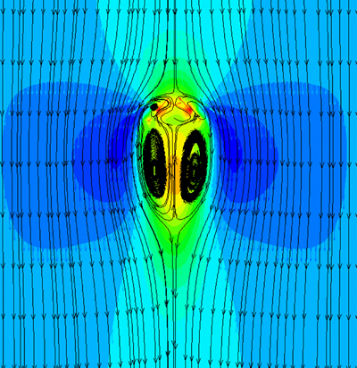
Fig. 7 Streamlines around a spherical cap bubble (case M: Re=197.81, Eo=32.71)
4 Conclusions
1) The simulated bubble shapes show that along with the increase of Eo and Re, the bubble shape deforms from spherical to oblate and eventually turns into spherical cap at relatively high Eo and Re, which is coincident with the experimental observations. However, the absence of prolate shape is presented without the introduction of viscoelastic dynamic equation, as distinct from the experimental results.
2) The calculation of the simulated bubble��s drag coefficient is obtained with a force balance based on the Newton��s second law. With regards to the simulated bubble drag coefficients, it is found that the simulated results show good conformity with the empirical correlation in literature.
3) In addition, the flow fields around bubbles in shear-thinning fluids are obtained on the reference coordinate system moving with the bubble. The simulated flow field around spherical bubble is symmetrical in the head and rear of bubble, indicating the well-known phenomenon of hindered rise of liquid following the bubble, whereas the distribution of streamlines and the bubble surface circulating vortex are slightly pointed tip for oblate bubble. When the bubble shape changes to spherical cap, a large recirculation zone formed by a pair of symmetric vortices reveals in the rear of the bubble.
References
[1] de KEE D. Nonlinear effects (discontinuties) in rheology [J]. Journal of Central South University of Technology, 2007, 14(1): 242-245.
[2] CHHABRA R P. Bubbles, drops and particles in non-newtonian fluids [M]. 2nd ed. Boca Raton, FL: CRC Press, 2007.
[3] NESSET J E, FINCH J A. A novel approach to prevent bubble coalescence during measurement of bubble size in flotation [J]. Journal of Central South University, 2014, 21(1): 338-343.
[4] ZHANG Li, YANG Chao, MAO Zai-sha. An empirical correlation of drag coefficient for a single bubble rising in non-Newtonian liquids [J]. Industrial & Engineering Chemistry Research, 2008, 47(23): 9767-9772.
[5] RODRIGUE D, de KEE D, FONG C F C M. A note on the drag coefficient of a single gas bubble in a power-law fluid [J]. The Canadian Journal of Chemical Engineering, 1999, 77(4): 766-768.
[6] RODRIGUE D. A simple correlation for gas bubbles rising in power-law fluids [J]. The Canadian Journal of Chemical Engineering, 2002, 80(2): 289-292.
[7] DEWSBURY K, KARAMANEV D G, MARGARITIS A. Hydrodynamic characteristics of free rise of light solid particles and gas bubbles in non-Newtonian liquids [J]. Chemical Engineering Science, 1999, 54(21): 4825-4830.
[8] MIYAHARA T, YAMANAKA S. Mechanics of motion and deformation of a single bubble rising through quiescent highly viscous Newtonian and non-Newtonian media [J]. Journal of chemical engineering of Japan, 1993, 26(3): 297-302.
[9] CLIFT R, GRACE J R, WEBER M E. Bubbles, drops, and particles [M]. New York: Academic Press, 1978.
[10] KARAMANEV D, DEWSBURY K, MARGARITIS A. Comments on the free rise of gas bubbles in non-Newtonian liquids [J]. Chemical Engineering Science, 2005, 60(16): 4655-4657.
[11] FAN Wen-yuan, MA You-guang, JIANG Shao-kun, YANG Ke, LI Huai-zhi. An experimental investigation for bubble rising in non-Newtonian fluids and empirical correlation of drag coefficient [J]. Journal of Fluids Engineering, 2010, 132(2): 021305.
[12] de KEE D, CHHABRA R P. A photographic study of shapes of bubbles and coalescence in non-Newtonian polymer solutions [J]. Rheologica acta, 1988, 27(6): 656-660.
[13] LI Shao-bai, MA You-guang, JIANG Shao-kun, ZHU Chun-ying, LI Huai-zhi. The drag coefficient and the shape for a single bubble rising in non-Newtonian fluids [J]. Journal of Fluids Engineering, 2012, 134(8): 084501.
[14] SOUSA R G, RIETHMULLER M L, PINTO A M F R, Camposa J B L M. Flow around individual Taylor bubbles rising in stagnant polyacrylamide (PAA) solutions [J]. Journal of non-Newtonian Fluid Mechanics, 2006, 135(1): 16-31.
[15] LIN Tsao-Jen, LIN Gen-Ming. An experimental study on flow structures of a single bubble rising in a shear-thinning viscoelastic fluid with a new measurement technique [J]. International journal of Multiphase Flow, 2005, 31(2): 239-252.
[16] LI Shao-bai, MA You-guang, ZHU Chun-ying, FU Tao-tao, LI Huai-zhi. The viscosity distribution around a rising bubble in shear-thinning non-Newtonian fluids [J]. Brazilian Journal of Chemical Engineering, 2012, 29(2): 265-274.
[17] ZHANG Li, YANG Chao, MAO Zai-sha. Numerical simulation of a bubble rising in shear-thinning fluids [J]. Journal of Non-Newtonian Fluid Mechanics, 2010, 165(11): 555-567.
[18] FUNFSCHILLING D, LI Huai-zhi. Flow of non-Newtonian fluids around bubbles: PIV measurements and birefringence visualization [J]. Chemical Engineering Science, 2001, 56(3): 1137-1141.
[19] FUNFSCHILLING D, LI Huai-zhi. Effects of the injection period on the rise velocity and shape of a bubble in a non-Newtonian fluid [J]. Chemical Engineering Research and Design, 2006, 84(10): 875-883.
[20] VAN SINT ANNALAND M, DIJKHUIZNE W, DEEN N G, KUIPERS J A M. Numerical simulation of behavior of gas bubbles using a 3-D front-tracking method [J]. AIChE Journal, 2006, 52(1): 99-110.
[21] YU Zhao, FAN Liang-Shih. Direct simulation of the buoyant rise of bubbles in infinite liquid using level set method [J]. The Canadian Journal of Chemical Engineering, 2008, 86(3): 267-275.
[22] RADL S, TRYGGVASON G, KHINAST J G. Flow and mass transfer of fully resolved bubbles in non-Newtonian fluids [J]. AIChE journal, 2007, 53(7): 1861-1878.
[23] KOYNOV A, KHINAST J, TRYGGVASON G. Mass transfer and chemical reactions in bubble swarms with dynamic interfaces [J]. AIChE journal, 2005, 51(10): 2786-2800.
(Edited by YANG Hua)
Foundation item: Project(21406141) supported by the National Natural Science Foundation of China; Project(20141078) supported by the Scientific Research Starting Foundation for Doctors of Liaoning Province, China; Project(L2014060) supported by the Foundation of Department of Education of Liaoning Province, China; Project(157B21) supported by the Scientific Research Starting Foundation for Doctors of Shenyang Aerospace University, China
Received date: 2015-04-08; Accepted date: 2015-09-23
Corresponding author: LI Run-dong, Professor, PhD; Tel: +86-18040038877; E-mail: leerd@tsinghua.edu.cn

