Trans. Nonferrous Met. Soc. China 24(2014) s42-s46
Impact damage behavior of sandwich composite with aluminum foam core
Moon Sik HAN1, Jae Ung CHO2
1. Faculty of Mechanical and Automotive Engineering, Keimyung University, 2800 Dalgubeoldaero, Dalseo-Gu, Daegu 704-701, Korea;
2. Division of Mechanical and Automotive Engineering, Kongju National University, 1223-24 Cheonan Daero, Seobuk-gu, Cheonan-si, Chungnam 331-717, Korea
Received 18 June 2013; accepted 30 March 2014
Abstract: Impact property of the sandwich composite with aluminum foam core was investigated by experiment and simulation analysis. Impact energies of 50, 70 and 100 J were applied to the specimens in impact tests. The results show that the striker penetrates the upper face sheet, causing the core to be damaged at 50 J test but the lower face sheet remains intact with no damage. At 70 J test, the striker penetrates the upper face sheet and the coreЈ¬and causes the lower face sheet to be damaged. Finally at 100 J test, the striker penetrates both the upper face sheet and the core, and even the lower face sheet. The experimental and simulation results agree with each other. By the confirmation with the experimental results, all these simulation results can be applied on structure study of real sandwich composite with aluminum foam core effectively.
Key words: sandwich composite; aluminum foam core; impact energy; maximum load
1 Introduction
As the composite material has superior mechanical properties as well as specific rigidity and strength, the need for the composite material in automobile and aviation industry continuously grows [1,2]. The multi-pore material including metal foam material, refers to the material in which pores are distributed regularly or irregularly [3]. Such multi-pore material has the advantages of lightweight, impact-proof, and noise-prevention properties. The composites addressed in this study are multi-pore aluminum foam whose specific gravity is 1/10 that of solid aluminum metal and has excellent impact energy-absorption capability [4]. Impact tests for sandwich composite with aluminum foam core were carried out to examine its mechanical properties [5,6]. The specimens in this study were sandwich composite with aluminum foam core where various impact energies such as 50 J, 70 J, and 100 J were applied for impact tests. The mechanical properties of sandwich composite with aluminum foam core by impact experiment were studied and compared with those of simulation analysis [7-10]. Through the experiments, the displacement configuration of the specimens was investigated. The relations of load to time and energy to time were analyzed. Through analysis, the data on impact property of specimens were secured and the design method of 3-dimensional model was suggested [10-14]. Through the finite element model, the mechanical properties of the material that is the same as the experimental material in impact tests were studied. Load, energy and deformation of the analysis result similar to the experimental data were verified in this study [15,16].
2 Experimental
As seen in Fig. 1, the thickness of the face sheet is 1 mm, its total height is 20 mm, and its length and width are both 100 mm.
As the characteristics of sandwich composite with aluminum foam core, the face sheet is Al-3003 and the core is Al-foam. And the mass of a specimen is 128 g, and the density of the core is 0.4 g/cm3. The impact energies of 50 J, 70 J and 100 J are applied to the impact tests, respectively. As the working principle of experimental apparatus, the impact energy is increased by increasing the impact velocity of penetrator.
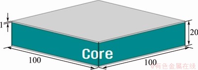
Fig. 1 Dimensions of test specimen (Unit: mm)
The experimental apparatus used in this experiment is IntronЎҜs Dynatup 9250 HV. The diameter of the striker is 12.5 mm. The impact energy of the striker is 50 , 70 J and 100 J. After the impact test, the computer data are produced. The experimental apparatus is shown in Fig. 2.
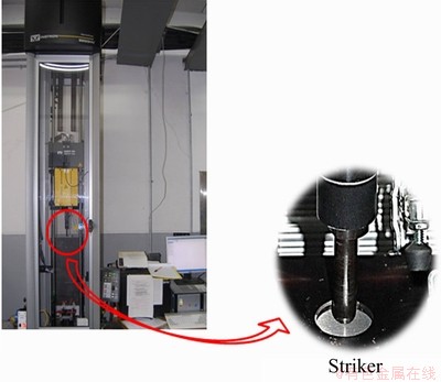
Fig. 2 Experimental apparatus used in experiment
3 Finite element modeling
Figure 3 shows the finite element model of which the material is the same as the experimental specimen. The finite element model is divided as tetrahedral element. The numbers of nodes and elements are 9832 and 6264, respectively. The material properties are shown in Table 1. The striker is assumed as rigid body. And the materials of the face sheet and core sheet are Al-3003 and Al-SAF40, respectively.
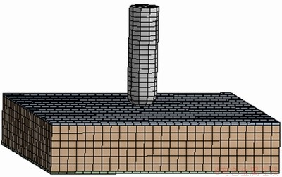
Fig. 3 Finite element model
Table 1 Material properties of analysis model
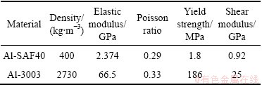
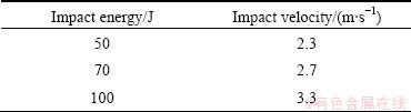
Figure 4 shows the constraint condition of simulation analysis. The striker is applied with impact speed as shown in Fig. 4. The contact between core sheet and face sheet is bonding. The contact between the striker and the specimen is frictionless. The end face of core sheet is set as fixed support. The impact velocity conditions on impact energy applied on striker are shown in Table 2.
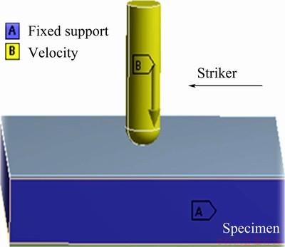
Fig. 4 Constraint condition of simulation analysis
Table 2 Impact velocity according to impact energy
4 Experimental and analysis results
4.1 Results after applying impact energy of 50 J
Figure 5 shows the cutting face of specimen after applying impact energy of 50 J in experiment and analysis. The striker penetrates 8 mm in specimen, showing that the striker generally causes damage to the middle of the core, penetrating the upper face sheet, but not damaging the lower face sheet. In experimental and analysis results, the striker pierces the specimen to the depth of 8 and 9 mm, respectively. The simulation result is not different from the experiment result.
Figure 6 shows the result in load graph over the time after applying impact energy of 50 J in experiment and analysis. In the experimental and analysis results, the maximum loads appear at 4 and 3.4 ms. And the maximum loads become 6 and 5.4 kN, respectively. The striker penetrates the upper face sheet before being gradually reduced in both of the results.
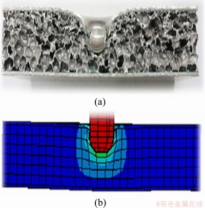
Fig. 5 Experimental (a) and analysis (b) configuration results after applying impact energy of 50 J
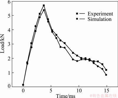
Fig. 6 Load graph due to time after applying impact energy of 50 J in experiment and analysis
Figure 7 shows the result in energy graph due to time after applying impact energy of 50 J in experiment and analysis. As shown in Fig. 7, the data increase simultaneously in the experimental and analysis results. Energies of 56 and 52 J happen at the time of 15 ms in experiment and analysis. As the impact behavior is not affected with the dent caused by striker in analysis, this result is lower than the experimental value.
4.2 Results after applying impact energy of 70 J
Figure 8 shows the cutting face of specimen after applying impact energy of 70 J. As shown in Fig. 8, the striker causes the damage to the core completely after penetrating the upper face sheet when applying 70 J, unlike the case of 50 J. The striker penetrates to the depth of 17 and 15 mm, respectively, in the experimental and analysis results. The simulation result is not different from the experiment result.
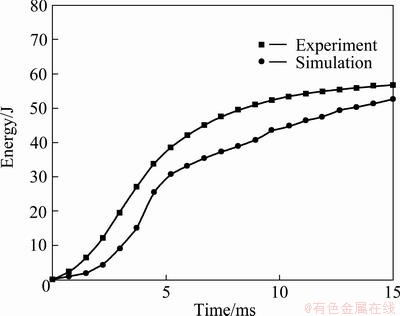
Fig. 7 Energy graph due to time after applying impact energy of 50 J in experiment and analysis
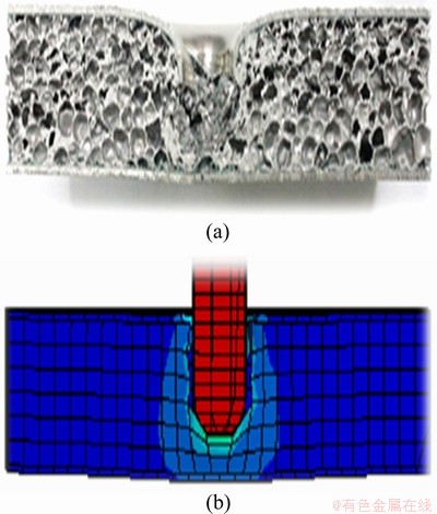
Fig. 8 Experimental (a) and analysis (b) configuration results after applying impact energy of 70J
Figure 9 shows the results in load graph over the time after applying impact energy of 70 J in experiment and analysis. When the striker penetrates the upper face sheet, the maximum loads on specimen in experiment and analysis are 5.7 and 5.5 kN at times of 3.5 and 3.2 ms, respectively. After that, these loads decrease gradually with the same trend.
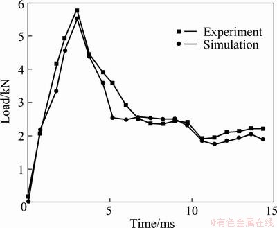
Fig. 9 Load graph due to time after applying impact energy of 70 J in experiment and analysis
Figure 10 shows the results in energy graph over the time after applying impact energy of 70 J in experiment and analysis. As shown in Fig. 10, the data increase simultaneously in the experimental and analysis results. The impact energies reach 70 and 65 J at the time of 15 ms in experiment and analysis. As the impact behavior is not affected with the dent caused by the striker in analysis, this result is lower than the experimental value unlike the case of 50 J.
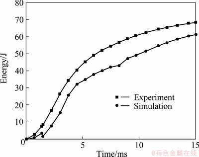
Fig. 10 Energy graph due to time after applying impact energy of 70 J in experiment and analysis
4.3 Result after applying impact energy of 100 J
Figure 11 shows the cutting face of specimen after applying impact energy of 100 J in experiment and analysis. As the same trend with experiment and simulation, the striker completely penetrates all of the upper face sheet, core and lower face sheet when 100 J is applied, whereas it causes a slight damage to the lower face sheet when 70 J is applied. The striker penetrates to the depth of 29 and 30 mm, respectively, in the experimental and analysis results. The simulation result is nearly the same as the experiment result.
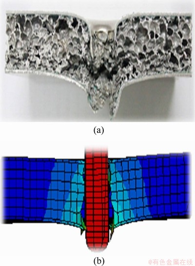
Fig. 11 Experimental (a) and analysis (b) configuration results after applying impact energy of 100J
Figure 12 shows the result in load graph over the time after applying impact energy of 100 J in experiment and analysis. When the striker is passing the upper face sheet, the maximum loads on specimen are 5 and 5.5 kN at times of 3 and 3.2 ms, respectively, in the experiment and analysis results. After that, these loads decrease and increase suddenly. This time is the time point to pass the lower sheet, and thereafter, the loads in experiment and analysis decrease gradually with the same trend.
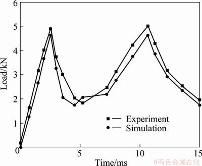
Fig. 12 Load graph due to time after applying impact energy of 100J in experiment and analysis
Figure 13 shows the results in energy graph due to time after applying impact energy of 100 J in experiment and analysis. As shown in Fig. 13, the data increase simultaneously in the experimental and analysis results. The impact energies reach 100 and 95 J at the time of 15 ms in experiment and analysis. As the impact energy becomes high, the impact behavior is not affected with the dent caused by the striker in analysis. The experimental and simulation results are similar to each other.

Fig. 13 Energy graph due to time after applying impact energy of 100 J in experiment and analysis
5 Conclusions
1) In case of applying impact energy of 50 J, the striker penetrates the upper face sheet and the damage proceeds until the middle of core. Such penetration causes the damage to the core, but not to the lower face sheet.
2) In case of applying impact energy of 70 J, the striker penetrates the upper face sheet and causes slight damage to the lower face sheet after penetrating the core.
3) In case of applying impact energy of 100 J, the striker penetrates the lower face sheet completely after penetrating the upper face sheet and the core.
4) The experimental and simulation results agree with each other. By the confirmation with experimental results, all these simulation results in this study can be applied to real sandwich composite structure with aluminum foam core effectively.
References
[1] LEE S K, CHO C D, CHO J U, BANG S O. In-plane characteristics of Al foam core and Al honeycomb core sandwich composites with an indented damage [J]. Annual Conference of KSME, 2011, 1: 226-227.
[2] RAMAMURTY U, KUMARAN M C. Mechanical property extraction through conical indentation of a closed-cell aluminum foam [J]. Acta Materialia, 2004, 52(1): 181-189.
[3] ZHOU J, SOBOYEJO W O. CompressionЁCcompression fatigue of open cell aluminum foams: Macro-/micro-mechanisms and the effects of heat treatment [J]. Materials Science and Engineering A, 2004, 369(1-2): 23-35.
[4] KONSTANTINIDIS I C H, PAPADOPOULOS D P, LEFAKIS H, TSIPAS D N. Model for determining mechanical properties of aluminum closed-cell foams [J]. Theoretical and Applied Fracture Mechanics, 2005, 43(2): 157-167.
[5] WEEKS C A, SUN C T. Modelling non-linear rate-dependent behavior in fiber-reinforced composites [J]. Composite Science and Technology, 1998, 58: 603-611.
[6] BAYNAL K, MAKARACI M, GULBUDAK K. Solution for failure analysis of automotive axle knuckle pull-out [J]. Int J of Automotive Technology, 2010, 11(5): 701-710.
[7] de GIORGI M, CAROFALO A, DATTOMA V, NOBILE R, PALANO F. Aluminum foams structural modeling [J]. Computers & Structures, 2010, 88(1-2): 25-35.
[8] LIAO M. Dislocation theory based short crack model and its application for aircraft aluminum alloys [J]. Engineering Fracture Mechanics, 2010, 77(1): 22-36.
[9] FRAGOMENI J, WHEELER R, JATA K. Effect of single and duplex aging on precipitation response, microstructure, and fatigue crack behavior in Al-Li-Cu alloy AF/C-458 [J]. Journal of Materials Engineering and Performance, 2005, 14(1): 18-27.
[10] FRAGOMENI J, WHEELER R, JATA K. Effect of single and duplex aging on precipitation response, microstructure, and fatigue crack behavior in Al-Li-Cu alloy AF/C-458 [J]. Journal of Materials Engineering and Performance, 2005, 14(1): 18-27.
[11] ACAR E, SOLANKI K. Improving the accuracy of vehicle crashworthiness response predictions using an ensemble of metamodels [J]. International Journal of Crashworthiness, 2009, 14(1): 49-61.
[12] DUBOIS D, ZELLMER H, MARKIEWICZ E. Experimental and numerical analysis of seat belt bunching phenomenon [J]. International Journal of Impact Engineering, 2009, 36(6): 763-774.
[13]  T, HOPPERSTAD O S, LANGSETH M, MALO K A. Effects of target thickness in blunt projectile penetration of Weldox 460 E steel plates [J]. International Journal of Impact Engineering, 2003, 28(4): 413-464.
[14] SHOKRIEH M M, HEIDARI-RARANI M, RAHIMI S. Influence of curved delamination front on toughness of multidirectional DCB specimens [J]. Composite Structures, 2012, 94(4): 1359-1365.
[15] COOPER V, IVANKOVIC A, KARAC A, McAULIFFE D, MURPHY N. Effects of bond gap thickness on the fracture of nano-toughened epoxy adhesive joints [J]. Polymer, 2012, 53(24): 5540-5553.
[16] MICHAILIDIS N, STERGIOUDI F, OMAR H, TSIPAS D N. An image-based reconstruction of the 3D geometry of an Al open-cell foam and FEM modeling of the material response [J]. Mechanics of Materials, 2010, 42(2): 142-147.
ЕЭДӯВБРҫИэГчЦОРНёҙәПІДБПөДіе»чЛрЙЛРРОӘ
Moon Sik HAN1, Jae Ung CHO2
1. Faculty of Mechanical and Automotive Engineering, Keimyung University, 2800 Dalgubeoldaero, Dalseo-Gu, Daegu 704-701, Korea;
2. Division of Mechanical and Automotive Engineering, Kongju National University, 1223-24 Cheonan Daero, Seobuk-gu, Cheonan-si, Chungnam 331-717, Korea
ХӘ ТӘЈәНЁ№эКөСйәНДЈДв·ЦОцСРҫҝЕЭДӯВБРҫИэГчЦОРНёҙәПІДБПөДіе»чРФДЬЎЈФЪіе»чІвКФКұЈ¬КФјюЛщКЬіе»чДЬ·ЦұрОӘ50Ўў70әН100 JЎЈҪб№ыұнГчЈ¬ФЪіе»чДЬОӘ50 JөДіе»чІвКФЦРЈ¬іеН·ҙ©НёБЛКФјюөДЙПІҝГж°еЈ¬К№РҫІҝКЬөҪЛрЙЛЈ¬ө«ПВІҝГж°еНкәГОЮЛрЈ»ФЪ70 JөДіе»чІвКФЦРЈ¬іеН·ҙ©НёБЛКФјюөДЙПІҝГж°еәНРҫІҝЈ¬ІўК№ПВІҝГж°еКЬөҪЛрЙЛЈ»ФЪ100 JөДіе»чІвКФЦРЈ¬іеН·І»ө«ҙ©НёБЛКФјюөДЙПІҝГж°еәНРҫІҝЈ¬»№ҙ©НёБЛПВІҝГж°еЎЈКөСйҪб№ыУлДЈДвҪб№ы»ҘПаОЗәПЎЈКөСйҪб№ыөДСйЦӨұнГчЈ¬ЛщУРДЈДвҪб№ыҫщҝЙУРР§өШУҰУГУЪХжКөЕЭДӯВБРҫИэГчЦОРНёҙәПІДБПөДҪб№№СРҫҝЎЈ
№ШјьҙКЈәИэГчЦОРНёҙәПІДБПЈ»ЕЭДӯВБРҫЈ»іе»чДЬЈ»ЧоҙуФШәЙ
(Edited by Xue-feng HE)
Foundation item: Project (2011-0006548) supported by the Basic Science Research Program through the National Research Foundation of Korea (NRF) funded by the Ministry of Education, Science, and Technology, Korea
Corresponding author: Jae Ung CHO; Tel: +82-41-521-9271; Fax: +82-41-555-9123; E-mail: jucho@kongju.ac.kr
DOI: 10.1016/S1003-6326(14)63286-6

