J. Cent. South Univ. Technol. (2011) 18: 1034-1040
DOI: 10.1007/s11771-011-0800-9
Locating method of fire source for spontaneous combustion of sulfide ores
LIU Hui(刘辉)1, 2, WU Chao(吴超)2, SHI Ying(石英)2
1. College of Quality and Safety Engineering, China Jiliang University, Hangzhou 310018, China;
2. School of Resources and Safety Engineering, Central South University, Changsha 410083, China
? Central South University Press and Springer-Verlag Berlin Heidelberg 2011
Abstract: In order to achieve a more efficient way to accurately detect the position of the fire source of spontaneous combustion underground mine, a simple fire source locating method, based on infrared scanning system which can determine the point where the highest temperature on the surface of igniting ores occurs, was proposed. First, the differential equations that describe heat flow in ore body were presented and the relationship between the surface temperature distribution and the depth and intensity of inner fire source was established with a relatively simple heat transfer model. With the solution of equation, the expression of the relationship between the surface temperature distribution and the inner fire source was deduced and the mathematical-physical model of heat transfer process was set up. Then, with the model, visualization of fire source on the basis of MATLAB simulation platform was realized. The results show that: 1) within 10 m, when the detecting depth is less than 2 m, the temperature perturbation on ores surface can change rapidly, and then slowly; after 4 m, in contrast, it changes very little, and is even close to zero at 10 m; 2) When it is close to self-ignition duration and the detective depths are 2, 5 and 10 m, respectively, the maximum temperature differences are correspondingly 0.5, 0.04 and 0.005 °C in the scope of 1 m×1 m; under the same condition, the maximum temperature differences are 1.391, 0.136 and 0.018 °C, respectively, in the scope of 2 m×2 m. Therefore, this system can be used to measure the temperature differences on the surface of ore body and determine the highest temperature point directly. Also, it is possible to determine the depth of fire source and its intensity by locating method of fire source indirectly.
Key words: sulfide ores; spontaneous combustion; location of fire source; detection
1 Introduction
Spontaneous combustion consists in the conversion of the chemical energy of some materials to heat owing to oxidation. If this heat is not dissipated, the materials are heated up and ignition occurs when the temperature reaches the critical point. It is well known that spontaneous combustion is one of the most serious safety problems in the mining of sulfide ore deposits [1]. Approximately 10% of iron, copper, lead, zinc and gold mines contain sulfide ores with spontaneous combustion potential in China [2]. A fire disaster from the spontaneous combustion of sulfide ores in a mine can produce large quantities of toxic gases and intense heat to pollute the whole mine, and may lead to large economic losses as well as loss of life. Up to now, many researchers in different countries have devoted considerable effort to investigating the mechanism, prediction, and extinguishing of a sulfide ore fire, explosive spontaneous detonation and dust explosion [1-6]. However, little work has been done to study the locating method of fire source of spontaneous ores combustion, which plays a dominating role in the process of preventing spontaneous combustion. There are a variety of test methods currently in use for detection of open fires and spontaneous combustion, such as temperature measurement methods [7], using NOAA/ AVHRR data [8], gases measurement methods [9], infrared detecting methods [10-11], combination of infrared thermographic and GPS topographic surveys [12]. To better solve the problem of fire source localization, seeking a reliable detection of fires is very essential.
In recent years, infrared thermal imagers have been successfully applied to a diverse range of subjects including detection of inner heat source in thermal texture maps [13], civil engineering and assessing landfill sites [14-15]. Infrared photography has also been used for assisting in the location of missing persons amongst building rubble in the aftermath of earthquakes. Fire source localization in fire nonage is an important direction in fire detection. Considering the ore body as a large volume containing a thermal source which maintains a constant temperature on one moment in time and covered by ores, information about fire source will be given feedback to its surface when the ore body with spontaneous combustion tendency emits infrared radiation. Fire detection technology of infrared thermal imaging can scan ore surface temperature field distribution by thermal imager, and then obtain temperature field information of ore body according to the anomalies of surface temperature distribution, so as to identify whether there is a fire within the ore body and its depth. In this work, a novel locating method of spontaneous combustion of sulfide ores based on infrared scanning system is presented.
2 Theoretical analysis and model
2.1 Thermal equilibrium of sulfide ore body
The emergence and development of self-ignition of the sulfide ores is an extremely complex process. The site of spontaneous combustion (see Fig.1), duration and extent vary widely, but still obey the heat balance equation. According to heat balance theory, the heat transfer between spontaneous combustion sites is satisfied with two conditions as follows [16]: 1) Heat output from inside to outside of ore body is equal to the one from the surface to the air. 2) Heat production in the ore body is equal to the heat output from inside to outside.
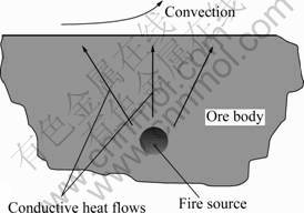
Fig.1 Energy flows in area of fire source
2.2 Partial differential equation of heat conduction
Considering the complexity of heat conduction in ore body of sulfide ores, in order to analyze and solve the problem easily, the following assumptions are made: 1) The ore body surrounding fire source is homogeneous and isotropic. 2) The area of fire source is small and the distance from the fire source to the ore body surface is much longer than the size of the fire source, which can be considered as a point fire source. 3) The heat convection inside ore body is ignored.
The one-dimensional temperature distribution in the ore body, along the vertical central axis of the fire source can be described as
 (1)
(1)
where ρ stands for the apparent density of sulfide ores, kg/m3; c is the apparent heat capacity of sulfide ores, J/(kg・K); T is the temperature field function; λ is the effective thermal conductivity, W/(m・ K); ?2 is Laplacian; and qv is the inner fire source, W.
In a steady state, Eq.(1) can be expressed by
 (2)
(2)
Corresponding to the heat exchange in ore body, the areas of the chemical change will give out excessive heat, which is known as inner fire source. The excessive heat is then transferred to ore body surface continuously until it achieves its heat equilibrium. The situation has been described by equations above. Due to the fact that the fire source is considered as a point heat source, the inner heat source term can be written as q・δ(r), so the heat exchange equation of point heat source in steady state can be defined as
 (3)
(3)
where q stands for the heat source intensity, δ(r) is the δ function which means that there is an infinite heat source at r =0 and no source at r≠0.
3 Locating method of fire source
The purpose of infrared scanning in the ore body is to confirm the position and height of spontaneous combustion of sulfide ores effectively according to the capacity of infrared radiation. In fact, the problem like estimation of heat source in heat conduction problem from temperature measurement is a typical inverse heat conduction problem (IHCP). One main characteristic of heat conduction problem is that its mathematical definite solution sometimes is improperly-posed and very difficult to solve. The reason for this is that the detecting data which contain the information of estimated parameters are a limited set of real numbers, and have an association with the observation noises in a certain form. In other words, if the detecting data have a small error, it will cause greater error of the parameter estimated. And the basis of successful IHCP is that there are some temperature differences and heat flux on the surface of the ore body. So, the intensity of ores spontaneous combustion is close to the depth of fire source and temperature difference on the ores surface.
3.1 Model solution
For a spherical coordinates system fixed to the center of the fire source, according to the heat transfer theory, the equation of heat conduction in spherical coordinates system is given by

 (4)
(4)
In the spherical coordinate system, the fire source is considered as the point heat source. Consequently, it is assumed that coordinate origin is at the position of the point fire source, as shown in Fig.2.
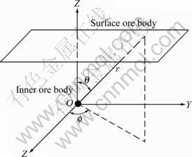
Fig.2 Basic thermal model in sphere coordinate system
Heat energy is transferred from inner to ore body surface, where the boundary temperature is not confined. The heat source as a point that transfers its heat in an infinite three-dimensional space for itself forming a symmetric temperature distribution is hypothesized. So, in the sphere coordinate system, Eqs.(3) and (4) mentioned above can be written as
 (5)
(5)
When r≠0, Eq.(5) becomes
 (6)
(6)
Its solution is T=-C1/r+C2, where both C1 and C2 are constants. Without losing universality, the following equation can be supposed
 (7)
(7)
When r=0, applying the volume integral to Eq.(3) with the integral volume dvε is a sphere whose center is at the coordinate origin, and its radius is at random small positive ε. The method can be described as
 (8)
(8)
According to Gauss’ law, there is


 (9)
(9)

 (10)
(10)
The following equation can be obtained:
 (11)
(11)
Substituting the value of C1 into Eq.(7), the surface temperature can be described as
 (12)
(12)
where r stands for the distance between the fire source and an arbitrary point on the ore body surface, m.
3.2 Determining highest temperature point on ores surface
As described above, heat transfer performance of fire source is formed with a balanced three-dimensional temperature field within ore body. Designating the fire source as central point O, and the vertical distance from point O to the surface of ore body as h, according to the Projection Theorem, projection of O in ore body surface is O′, and A is considered as an arbitrary point on its surface. A specific description about location of fire source is shown in Fig.3. The following equation can be obtained according to the Right Triangle Theorem:
 (13)
(13)

Fig.3 Schematic diagram of fire source of spontaneous ignition for locating
The surface temperature distribution T(x) can be established as
 (14)
(14)
where Ta is the ambient temperature, °C.
And the temperature differences on the ore body surface can be described as
 (15)
(15)
Obviously, point O′, which is just located vertically from the inner fire source, is the one of the highest temperatures on the ore body surface when x=0:
 (16)
(16)
Equations (14)-(16) show that the depth and intensity of fire source are unknown. In reality, the surface temperature can be measured by an infrared detector and its temperature differences can be calculated. Also, the value of x can be obtained by measurement in situ. For this reason, it is possible to detect the information of the inner fire source, including the depth and the intensity.
4 Simulation results and discussion
4.1 Heat conduction and visualization of fire source
On the basis of the detecting level of IRI-1011 thermal infrared imager (technical parameters are shown in Table 1), the detecting area (1.76 m×1.76 m) was obtained as the simulation range. When the internal temperature of ore was over 60 °C, the ores were close to self-ignition duration, which was discussed in Ref.[1]. So, according to the mine underground condition, taking the ambient temperature t0=30 °C and the coefficient of heat conductivity of sulfide ores λ=0.84 W/(m?°C), simulating the thermal transfer in the condition of h=10, 5, 2 m respectively when the temperature were 60 °C and 100 °C, the heat transfer process and temperature distribution are shown in Figs.4 and 5, respectively.
Table 1 Technical parameters of IRI-1011

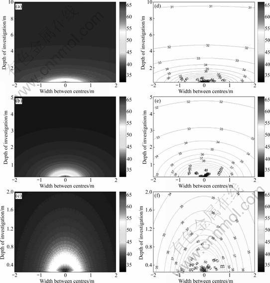
Fig.4 Contour maps of temperature field for h=10 m (a), 5 m (b) and 2 m (c) and isotherm distribution for h=10 m (d), 5 m (e) and 2 m (f) at fire source temperature of 60 °C
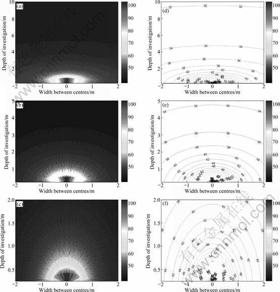
Fig.5 Contour maps of temperature field for h=10 m (a), 5 m (b) and 2 m (c) and isotherm distribution for h=10 m (d), 5 m (e) and 2 m (f) at fire source temperature of 100 °C
4.2 Results and discussion
The heat of fire source transfers from the centre to surroundings in the homogeneous medium. From Figs.4 and 5, it can be seen that the core temperature (point O) is the highest and the heat diffuses all around the fire source because of the heat exchange effects, forming the temperature dropping grads, and the nearer the fire source is, the greater the grads will be. So, the temperature difference effects are obvious according to different detecting depths and detecting areas.
4.2.1 Effect of investigation depth on detection results
As mentioned above, there are temperature differences clearly on the surface of ore body, which can cause the change of temperature field, and reach the maximum at point O′. The temperature difference between arbitrary point A on ores surface and O′ can be gained by Eq.(7). The situations that temperature difference changes with combustion intensity due to different depth of fire source are shown in Fig.6.
When the fire source temperature is equal to 60 °C, the temperature difference of ore surface, which stems from fire source, will reduce gradually with the increase of detecting depth (when the depth is less than 2 m it can change rapidly, and then slowly; but it changes very little after 4 m). It is even close to zero at 10 m and finally tends to ambient temperature. However, with the increase of heat intensity, temperature rises gradually. Although the temperature of ore surface is obviously higher at 100 °C than that at 60 °C, with the increase of detecting depth, it will diminish quickly when detecting depth is less than 2 m, then decrease slowly. The changing trend of temperature difference is similar to that of 60 °C. In general, when the detecting area is 2 m×2 m, or 1 m×1 m, the maximum of temperature difference will be influenced greatly by detecting depth; but the trend of their temperature change is almost unanimous. It is accordant with practice. When the fire source is deeper, this will be more latent. This will also increase the difficulty of the detection.

Fig.6 Distribution of temperature difference on surface of ore body with increasing detecting depth: (a) t0=60 °C; (b) t0= 100 °C
4.2.2 Effect of light-sensing surface area
Figures 7(a)-(c) show that spontaneous ignition ores form temperature difference on the surface from centre to surrounding, and the larger the detection zone is, the more the temperature difference will be. When it is close to self-ignition duration (60 °C) and the detective depths are 2, 5 and 10 m, respectively, the maximum temperature differences are 0.5 °C, 0.04 °C and 0.005 °C correspondingly in the scope of 1 m×1 m. Under the same condition, the maximum temperature differences are 1.391 °C, 0.136 °C and 0.018 °C, respectively, in the scope of 2 m×2 m. It is undoubted that the effects of utilizing thermal imaging equipment are better by enlarging the light-sensing area, but because of the total field of view (TFOV) and the field condition, the light-sensing area will be not too ideal. For this detection system of IRI-1011 thermal infrared imager, the light-sensing area is about 1 m×1 m when detecting distance is nearly equal to 3 m, and it is less than 2 m× 2 m at 5 m of detecting distance, so the temperature differences obtained in the scope of 1 m×1 m are little when the position of fire source is deeper.

Fig.7 Distribution of temperature difference on surface of ore body with increase of light-sensing area: (a) h=2 m; (b) h=5 m; (c) h=10 m
It is possible to detect fire source theoretically when the detection depth is over 10 m, but it requires more advanced detection system. In the view that air is the necessary condition of self-ignition within ore body, and in the normal condition, the air is difficult to penetrate to the 10 m depth of ore body, there is not much chance for over 10 m depth of ore body. Besides, it can be seen from the temperature variation curves of different fire source intensity that, the higher the temperature of fire source is, the faster and clearer the change of temperature information on the surface of the ore will be.
Theoretical analysis and numerical simulation show that there is certainly temperature difference on the surface of ore body which is about to ignite. As long as the fire source detecting system has the precision of distinguishing the characteristic of temperature difference, and determining the point (O′) where the highest temperature happens on the surface of igniting ore by the thermal imaging system, using Eqs.(6) and (10), it is possible to determine the fire source and its intensity. As far as the IRI-1011 thermal infrared imager used in research is considered, the ideal detecting depth is no more than 5 m.
5 Conclusions
1) According to the heat balance theory, the heat transfer model of fire source in ore body of spontaneous combustion is established, and the expression of relationship between the surface temperature distribution and the depth and intensity of inner fire source is deduced.
2) The simulation results show that for the ore body close to self-ignition duration (60 °C), the detection effect is better when fire source depth is less than 10m. And it is possible to detect fire source theoretically when the fire source depth is over 10 m, so long as there is a more advanced detection system.
3) The locating method of fire source is proposed based on scanning of infrared thermal imager which is the key for determining the point where the highest temperature happens on the surface of igniting ore by the thermal imaging system. And as far as the IRI-1011 thermal infrared imager used in research is considered, the ideal detecting depth is no more than 5 m.
References
[1] LIU Hui, WU Chao, PAN Wei, SHI Ying. Index optimization and forecast model of spontaneous combustion of sulfide ore dump during early stage [J]. Science and Technology Review, 2009, 27(3): 46-50. (in Chinese)
[2] WU Chao, LI Zi-jun. A simple method for predicting the spontaneous combustion potential of sulfide ores at ambient [J]. Transaction of Mining and Metallurgy Institute, 2005, 112(2): 125-128.
[3] CRANNEY D H. Assessing the hazards of blasting in reactive sulfide ores and the application of products to mitigate these hazards [C]// Proceedings of 28th Annual Institute on Mining Health, Safety and Research. Salt Lake City: American Institute of Mining and Metallurgy, 1997: 111-117.
[4] LIU Hui, WU Chao, CUI Yan, WANG Fa-song. Fractal characterization of the oxidation of sulfide ores [J]. Journal of Safety and Environment, 2009, 9(3): 113-116. (in Chinese)
[5] ROSENBLUM F, SPIRA P. Evaluation of hazard from self-heating of sulfide rock [J]. CIM Bull, 1995, 88(989): 44-49.
[6] WU Chao, LI Zi-jun, LI Ming. Chemical thermodynamic mechanism of sulfide ores during oxidization and self-heating process [C]// Proceedings of the 2007 International Symposium on Mining Safety Science and Technology. Beijing: Science Press, 2007: 2435-2439.
[7] HOGLAND W, MARQUES M. Physical, biological and chemical processes during storage and spontaneous combustion of waste fuel [J]. Resources, Conservation and Recycling, 2003, 40(1): 53-69.
[8] AGARWAL R, SINGH D, CHAUHAN D S and SINGH K P. Detection of coal mine fires in the Jharia coal field using NOAA/AVHRR data [J]. Journal of Geophysics and Engineering, 2006, 3(3): 212-218.
[9] KIM A G. Locating fires in abandoned underground coal mines [J]. International Journal of Coal Geology, 2004, 59(1/2): 49-62.
[10] WANG Zhen-ping, CHENG Wei-min, XIN Song, SONG Xian-ming, SU Shao-gui. The calculation of close-range coal inflammation position at coal-roads based on infrared detecting and inverse heat conduction technology [J]. Journal of China Coal Society, 2003, 28(6) : 603-607. (in Chinese)
[11] CHENG Wei-min. Study of infrared detecting technology of the spontaneous fire position at the coal road on mines [C]// Progress in Safety Science and Technology. Beijing: Chemical Industry Press, 2000: 586-590.
[12] CARPENTIER O, DEFER D, ANTCZAK E, DUTHOIT B. The use of infrared thermographic and GPS topographic surveys to monitor spontaneous combustion of coal tips [J]. Applied Thermal Engineering, 2005, 25(17/18): 2677-2686.
[13] GAO Chun-fang, LI Kai-yang, ZHANG Shao-ping. A novel approach of analyzing the relation between the inner heat source and the surface temperature distribution in thermal texture maps [C]// Proceedings of the 2005 IEEE Engineering in Medicine and Biology 27th Annual Conference. Shanghai, 2005: 623-626.
[14] CUI Long-lian, AN Li-qian, Mao Ling-tao, Li Jian-hui. Application of infrared thermal testing and mathematical models for studying the temperature distributions of the high-speed waterjet [J]. Journal of Materials Processing Technology, 2009, 209(9): 4360-4365.
[15] MADRUGA F J, MUNOZ J M, GONZALEZ D A, TEJERO J I, COBO A, GILOLGA J L, CONDE M, LOPEZ-HIGUERA J M. Field test of infrared thermography applied to biogas controlling in landfill sites [C]// Proceedings of SPIE―The International Society for Optical Engineering. Orlando FL, USA, 2007: 65411B-1-65411B-6.
[16] SHENG Yao-bing, WANG Yun-jia, SHU Li-yong. Investigation of a method for calculating the spontaneous combustion depth of a mine rock dump and its application [J]. Journal of China University of Mining & Technology, 2008, 37(4): 545-549. (in Chinese)
(Edited by YANG Bing)
Foundation item: Project(2006BAK04B03) supported by the National Basic Research Program of China; Project(CX2009B053) supported by Innovation Foundation for Postgraduate Students of Hunan Province, China; Project(2009ybfz08) supported by the Doctoral Dissertation of Central South University, China
Received date: 2010-05-25; Accepted date: 2010-10-22
Corresponding author: LIU Hui, PhD; Tel: +86-13735867716; E-mail: liuhui2003@126.com

